EP0944451B1 - Modular cutting tool assembly - Google Patents
Modular cutting tool assembly Download PDFInfo
- Publication number
- EP0944451B1 EP0944451B1 EP97947851A EP97947851A EP0944451B1 EP 0944451 B1 EP0944451 B1 EP 0944451B1 EP 97947851 A EP97947851 A EP 97947851A EP 97947851 A EP97947851 A EP 97947851A EP 0944451 B1 EP0944451 B1 EP 0944451B1
- Authority
- EP
- European Patent Office
- Prior art keywords
- cutting insert
- cutting
- insert
- lateral
- central axis
- Prior art date
- Legal status (The legal status is an assumption and is not a legal conclusion. Google has not performed a legal analysis and makes no representation as to the accuracy of the status listed.)
- Expired - Lifetime
Links
Images


Classifications
-
- B—PERFORMING OPERATIONS; TRANSPORTING
- B23—MACHINE TOOLS; METAL-WORKING NOT OTHERWISE PROVIDED FOR
- B23C—MILLING
- B23C5/00—Milling-cutters
- B23C5/16—Milling-cutters characterised by physical features other than shape
- B23C5/20—Milling-cutters characterised by physical features other than shape with removable cutter bits or teeth or cutting inserts
- B23C5/22—Securing arrangements for bits or teeth or cutting inserts
- B23C5/2204—Securing arrangements for bits or teeth or cutting inserts with cutting inserts clamped against the walls of the recess in the cutter body by a clamping member acting upon the wall of a hole in the insert
- B23C5/2208—Securing arrangements for bits or teeth or cutting inserts with cutting inserts clamped against the walls of the recess in the cutter body by a clamping member acting upon the wall of a hole in the insert for plate-like cutting inserts
- B23C5/2213—Securing arrangements for bits or teeth or cutting inserts with cutting inserts clamped against the walls of the recess in the cutter body by a clamping member acting upon the wall of a hole in the insert for plate-like cutting inserts having a special shape
-
- B—PERFORMING OPERATIONS; TRANSPORTING
- B23—MACHINE TOOLS; METAL-WORKING NOT OTHERWISE PROVIDED FOR
- B23C—MILLING
- B23C2200/00—Details of milling cutting inserts
- B23C2200/04—Overall shape
- B23C2200/045—Round
-
- B—PERFORMING OPERATIONS; TRANSPORTING
- B23—MACHINE TOOLS; METAL-WORKING NOT OTHERWISE PROVIDED FOR
- B23C—MILLING
- B23C2200/00—Details of milling cutting inserts
- B23C2200/16—Supporting or bottom surfaces
- B23C2200/167—Supporting or bottom surfaces star form
-
- B—PERFORMING OPERATIONS; TRANSPORTING
- B23—MACHINE TOOLS; METAL-WORKING NOT OTHERWISE PROVIDED FOR
- B23C—MILLING
- B23C2200/00—Details of milling cutting inserts
- B23C2200/36—Other features of the milling insert not covered by B23C2200/04 - B23C2200/32
- B23C2200/363—Lines for indexing round inserts
-
- B—PERFORMING OPERATIONS; TRANSPORTING
- B23—MACHINE TOOLS; METAL-WORKING NOT OTHERWISE PROVIDED FOR
- B23C—MILLING
- B23C2210/00—Details of milling cutters
- B23C2210/16—Fixation of inserts or cutting bits in the tool
- B23C2210/168—Seats for cutting inserts, supports for replacable cutting bits
-
- B—PERFORMING OPERATIONS; TRANSPORTING
- B23—MACHINE TOOLS; METAL-WORKING NOT OTHERWISE PROVIDED FOR
- B23C—MILLING
- B23C2210/00—Details of milling cutters
- B23C2210/66—Markings, i.e. symbols or indicating marks
-
- Y—GENERAL TAGGING OF NEW TECHNOLOGICAL DEVELOPMENTS; GENERAL TAGGING OF CROSS-SECTIONAL TECHNOLOGIES SPANNING OVER SEVERAL SECTIONS OF THE IPC; TECHNICAL SUBJECTS COVERED BY FORMER USPC CROSS-REFERENCE ART COLLECTIONS [XRACs] AND DIGESTS
- Y10—TECHNICAL SUBJECTS COVERED BY FORMER USPC
- Y10T—TECHNICAL SUBJECTS COVERED BY FORMER US CLASSIFICATION
- Y10T407/00—Cutters, for shaping
- Y10T407/19—Rotary cutting tool
- Y10T407/1906—Rotary cutting tool including holder [i.e., head] having seat for inserted tool
- Y10T407/1926—Plural simultaneously usable separable tools in common seat or common clamp actuator for plural simultaneously usable tools
-
- Y—GENERAL TAGGING OF NEW TECHNOLOGICAL DEVELOPMENTS; GENERAL TAGGING OF CROSS-SECTIONAL TECHNOLOGIES SPANNING OVER SEVERAL SECTIONS OF THE IPC; TECHNICAL SUBJECTS COVERED BY FORMER USPC CROSS-REFERENCE ART COLLECTIONS [XRACs] AND DIGESTS
- Y10—TECHNICAL SUBJECTS COVERED BY FORMER USPC
- Y10T—TECHNICAL SUBJECTS COVERED BY FORMER US CLASSIFICATION
- Y10T407/00—Cutters, for shaping
- Y10T407/20—Profiled circular tool
-
- Y—GENERAL TAGGING OF NEW TECHNOLOGICAL DEVELOPMENTS; GENERAL TAGGING OF CROSS-SECTIONAL TECHNOLOGIES SPANNING OVER SEVERAL SECTIONS OF THE IPC; TECHNICAL SUBJECTS COVERED BY FORMER USPC CROSS-REFERENCE ART COLLECTIONS [XRACs] AND DIGESTS
- Y10—TECHNICAL SUBJECTS COVERED BY FORMER USPC
- Y10T—TECHNICAL SUBJECTS COVERED BY FORMER US CLASSIFICATION
- Y10T407/00—Cutters, for shaping
- Y10T407/22—Cutters, for shaping including holder having seat for inserted tool
- Y10T407/2202—Plural spaced seats and common holder
-
- Y—GENERAL TAGGING OF NEW TECHNOLOGICAL DEVELOPMENTS; GENERAL TAGGING OF CROSS-SECTIONAL TECHNOLOGIES SPANNING OVER SEVERAL SECTIONS OF THE IPC; TECHNICAL SUBJECTS COVERED BY FORMER USPC CROSS-REFERENCE ART COLLECTIONS [XRACs] AND DIGESTS
- Y10—TECHNICAL SUBJECTS COVERED BY FORMER USPC
- Y10T—TECHNICAL SUBJECTS COVERED BY FORMER US CLASSIFICATION
- Y10T407/00—Cutters, for shaping
- Y10T407/22—Cutters, for shaping including holder having seat for inserted tool
- Y10T407/2208—Plural simultaneously usable separable tools in common seat or common clamp actuator for plural simultaneously usable tools
-
- Y—GENERAL TAGGING OF NEW TECHNOLOGICAL DEVELOPMENTS; GENERAL TAGGING OF CROSS-SECTIONAL TECHNOLOGIES SPANNING OVER SEVERAL SECTIONS OF THE IPC; TECHNICAL SUBJECTS COVERED BY FORMER USPC CROSS-REFERENCE ART COLLECTIONS [XRACs] AND DIGESTS
- Y10—TECHNICAL SUBJECTS COVERED BY FORMER USPC
- Y10T—TECHNICAL SUBJECTS COVERED BY FORMER US CLASSIFICATION
- Y10T407/00—Cutters, for shaping
- Y10T407/22—Cutters, for shaping including holder having seat for inserted tool
- Y10T407/2272—Cutters, for shaping including holder having seat for inserted tool with separate means to fasten tool to holder
- Y10T407/2274—Apertured tool
-
- Y—GENERAL TAGGING OF NEW TECHNOLOGICAL DEVELOPMENTS; GENERAL TAGGING OF CROSS-SECTIONAL TECHNOLOGIES SPANNING OVER SEVERAL SECTIONS OF THE IPC; TECHNICAL SUBJECTS COVERED BY FORMER USPC CROSS-REFERENCE ART COLLECTIONS [XRACs] AND DIGESTS
- Y10—TECHNICAL SUBJECTS COVERED BY FORMER USPC
- Y10T—TECHNICAL SUBJECTS COVERED BY FORMER US CLASSIFICATION
- Y10T407/00—Cutters, for shaping
- Y10T407/23—Cutters, for shaping including tool having plural alternatively usable cutting edges
- Y10T407/235—Cutters, for shaping including tool having plural alternatively usable cutting edges with integral chip breaker, guide or deflector
Definitions
- the present invention relates to cutting tools and, in particular, it concerns a modular cutting tool assembly in which cutting inserts with different orders of rotational symmetry can be used alternately with a single tool holder.
- Cutting inserts with round cutting edges exhibit rotational symmetry and could theoretically be continuously indexable in any angular position to accommodate actually observed wear. In practice, however, round inserts have also become restricted to use with a discrete number of indexing stations, angularly spaced by an equal shift angle. The angular shift between the indexing stations is referred to as the "angular pitch" of the insert.
- the insert comprises a top surface which is intersected by a frusto-conical edge surface to form therewith a round cutting edge.
- Five equidistantly spaced flat facets are formed in the edge surface. Upper ends of the facets are spaced below the cutting edge.
- the insert is fixed through a screw to a seat of a holder, such that two of the facets are pressed against respective flat contact areas formed on a locating surface of the holder.
- the present invention provides a modular cutting tool assembly in which cutting inserts with various differing numbers of indexing stations or differing cutting geometries can be used alternately in a generic tool holder pocket structure.
- the insert-receiving pocket is structured to provide circumscribing "three-point" locating and support features.
- a reduced-symmetry cutting insert is provided with protruding features which inhibit erroneous indexing of the insert in an improper angular position.
- the indexable inserts of the present invention may form part of a set of coordinated interchangeable inserts for use with a tool holder of a single size and shape.
- the inserts and receiving pockets of the invention are of great value in many applications including, but not limited to, milling cutters, broaches, turning tools and the like.
- the present invention provides an indexable insert which has a plurality of discrete abutment surfaces, three of which are used at a time.
- a modular cutting tool assembly comprising: (a) a tool holder having at least one insert receiving pocket with a base and a plurality of lateral support surfaces; (b) a first cutting insert receivable within the pocket, the first cutting insert having an upper surface, a bottom surface and a peripheral flank surface, the peripheral flank surface being configured to provide abutment features with m ⁇ n -fold rotational symmetry about a central axis of the first cutting insert such that the first cutting insert can be restrained against the lateral support surfaces in any of m ⁇ n angular positions, for at least one value of each of n and m where n ⁇ 3 and m ⁇ 2; and (c) a second cutting insert receivable within the pocket, the second cutting insert having an upper surface, a bottom surface and a peripheral flank surface, the peripheral flank surface being configured to provide reduced-symmetry abutment features with only n -fold rotational symmetry about a central axis of the second cutting insert
- the peripheral flank surface of the first cutting insert is configured such that an upper cross-section through the first cutting insert perpendicular to the central axis and proximal to the upper surface exhibits a non-recessed form.
- the upper cross-section corresponds to a substantially regular polygon with m ⁇ n sides.
- the upper cross-section is substantially circular.
- the peripheral flank surface of the second cutting insert is shaped such that a lower cross-section taken through the lower part of the second cutting insert perpendicular to the central axis at a point closer to the bottom surface exhibits a recessed form.
- the first entering angle differs from the second entering angle by about 180°/ n .
- a tool holder for alternately receiving a first cutting insert indexable in exactly n rotational positions and a second cutting insert indexable in m ⁇ n rotational positions, for at least one value of each of n and m where n ⁇ 3 and m ⁇ 2, the tool holder comprising at least one insert receiving pocket defined with reference to an axis passing through the pocket with which a central axis of the cutting inserts is to be aligned, the pocket having: (a) a base for supporting the cutting inserts; (b) first, second and third lateral support surfaces angularly spaced around, and substantially equidistant from, the axis; (c) a first lateral hollow located between the first and second lateral support surfaces; and (d) a second lateral hollow located between the second and third lateral support surfaces, wherein the first and second lateral hollows are formed such that geometrical mappings of the first and second lateral support surfaces by rotation through 360°/( m ⁇ n
- the first, second and third lateral support surfaces define, respectively, first, second and third planes, the first plane being related to the second plane by a rotation through 360°/ n about the axis.
- the second and third planes of the pocket are substantially coplanar.
- a cutting insert having n -fold rotational symmetry for some value of n where n ⁇ 3, the cutting insert being indexable exclusively at n indexing stations within an insert receiving pocket which is configured to receive alternately cutting inserts having both n -fold rotational symmetry and m ⁇ n -fold rotational symmetry for some value of m where m ⁇ 2,
- the cutting insert comprising a unitary structure having an upper surface bounded by a cutting edge, a base, a peripheral flank surface and a central axis, wherein the peripheral flank surface is shaped such that an outline of a first cross-section taken through the lower part of the cutting insert perpendicular to the central axis exhibits a recessed form including: (a) n corner portions angularly spaced around the central axis, the corner portions corresponding to n -fold rotationally symmetric lateral abutment features; and (b) support protrusions protruding outwards from the peripheral flank surface
- the peripheral flank surface is further shaped such that an outline of a second cross-section taken through the cutting insert perpendicular to the central axis and proximal to the upper surface exhibits a non-recessed form.
- the corner portions correspond substantially to corner regions of a regular polygon of n sides.
- the present invention is a modular cutting tool assembly employing round and polygonal cutting inserts with peripheral flank surfaces shaped to provide abutment surfaces for opposing high torques, and corresponding insert-receiving pockets of tool holders.
- the geometry of the abutment surfaces enables the use of sets of inserts with differing numbers of indexing positions and differing entering angles within a given pocket geometry.
- Figures 1A-1E show a first cutting insert, generally designated 10, constructed and operative according to the teachings of the present invention.
- cutting insert 10 has an upper surface 12 bounded by a cutting edge 14, a base 16, and a peripheral flank surface 18.
- the shape of peripheral flank surface 18 varies along the height of cutting insert 10 . Near the top of peripheral flank surface 18 , it conforms to the round or polygonal geometry of the cutting edge so as to provide support for cutting edge 14.
- Lower down cutting insert 10 peripheral flank surface 18 is shaped to provide transverse abutment surfaces, preferably with recessed features such as channels, and in certain cases, as chevron-type channels. This latter possibility leads to a lower cross-sectional geometry which approximates to an n -pointed star.
- n -pointed star refers to a rotationally symmetric shape with n outermost points each of which is joined to its nearest neighbors by an inward pointing chevron or "V-shape".
- An example of a 5-pointed star is shown in Figure 2B. It should be noted that the lower peripheral flank surfaces of certain preferred cutting inserts of the present invention are described as having “approximately” or “substantially” n -pointed star geometry since the points and/or the chevron bases may be flattened, as will be described in more detail below.
- rotationally-symmetric is used herein in the description and claims to refer to shapes which are invariant under rotation through an angle of 360°/ n where n is at least three.
- the term so defined includes regular polygons of three or more sides, whether straight-sided or made up of more complex combinations of straight or curved line segments.
- the term also includes circular shapes.
- the abutment surface geometry permits the use of these lower symmetry inserts within pockets also designed to receive higher symmetry cutting inserts, as will be described in more detail below.
- recessed and non-recessed shapes Reference is made in the description and claims to recessed and non-recessed shapes. It should be understood that the term "recess" is used in the description and claims to refer to a part of a shape or surface which is concave or otherwise generates a hollow. In more precise terms, a recess may be identified as any part of a shape or surface which lies interior to a virtual straight line connecting adjacent parts of the shape or surface. Conversely, a shape which at no point has a recess so defined is termed a "non-recessed" shape. Thus, the chevron of an n -pointed star constitutes a "recess" as herein defined, whereas a regular polygon is classified as a non-recessed shape.
- upper surface or rake 12 has, in this example, an inwardly slanted, peripheral annular portion 20 , bordered at the outer perimeter thereof by cutting edge 14 , and a flat, inner annular portion 22 , perpendicular to the axis of cutting insert 10 .
- Upper surface 12 may also have additional chip control features such as a pattern of indentations or ridges.
- additional chip control features such as a pattern of indentations or ridges.
- Figure 1E One such possibility is shown in Figure 1E. Again, it should be noted that the cutting insert is considered rotationally symmetric independent of the fact that the indices and various other features of the upper surface may not conform to this symmetry.
- inner annular portion 22 intersects at its inner extreme with a cylindrical extension 24 of a central, standard so-called “partly cylindrical” bore 26 , used for the passage of a standard counter-sunk clamping screw (not shown).
- a standard counter-sunk clamping screw not shown.
- peripheral flank surface 18 it is a particular feature of certain preferred cutting inserts of the present invention that peripheral flank surface 18 is shaped such that a first cross-section taken through the cutting insert perpendicular to the central axis and proximal to upper surface 12 is bounded by a non-recessed form, whereas a second cross-section taken through the cutting insert perpendicular to the central axis at a point closer to base 16 exhibits n -fold rotational symmetry and includes recessed features for providing abutment surfaces for opposing torque about the central axis.
- peripheral flank surface 18 may be sub-divided along the height of cutting insert 10 into at least two, and typically three, portions.
- a first portion adjacent to cutting edge 14 is denoted the relief flank surface 28 and has a non-recessed cross-sectional outline.
- the lower portion of peripheral flank surface 18 constitutes a ribbed flank surface 30 .
- Ribbed flank surface 30 is preferably linked to relief flank surface 28 by a transition flank surface portion 32 which provides a gradual transition between the two forms, as will be described below.
- Relief flank surface 28 typically corresponds to the geometry of the cutting edge employed.
- relief flank surface 28 has a frustro-conical form, having a circular cross-section corresponding to the circular cutting edge illustrated.
- relief flank surface 28 may be described as having substantially constant cross-sectional geometry perpendicular to the central axis at all heights, although the dimensions of this geometry may vary somewhat with height.
- Relief flank surface 28 preferably extends downwards from cutting edge 14 at least about a tenth of the height of cutting insert 10.
- Relief flank surface 28 is typically inclined at an acute angle ⁇ relative to the central axis of cutting insert 10.
- Angle ⁇ is commonly denoted the insert's "primary normal relief angle” and is preferably less than about 20° and typically about 7°.
- ⁇ may be about 0° such that relief flank surface 28 is cylindrical.
- ribbed flank surface 30 is preferably implemented as a frustro-pyramidal ribbed surface with channels 34 formed between projecting ridges 36 .
- Channels 34 preferably have a chevron-type cross-section.
- Ribbed flank surface 30 extends from base 16 to a plane perpendicular to the insert axis indicated in Figure 1B as plane I-I. Ribbed flank surface 30 preferably extends for at least about an eighth, and typically for at least about a quarter, of the height of the cutting insert. Depending on the design of transition flank surface 32 , ribbed flank surface 30 may extend along the majority of the height of peripheral flank surface 18.
- Ribbed flank surface 30 may be regarded as having " n " ridges 36 each having a crest which blends smoothly with a pair of planar, oppositely sloping, lateral abutment surfaces 38 . At the junction of adjacent ridges, adjacent abutment surfaces 38 intersect at smoothed root regions 40 .
- the number of ridges is equal to the number of available indexing positions of the insert. For a circular cutting edge, n is preferably at least 5, and typically 8 or more.
- the generating segment subtends a central pitch angle ⁇ equal to 360°/n.
- two spaced-apart abutment surfaces 38 are coplanar.
- ⁇ 45°
- ⁇ 45°
- ⁇ 67.5°
- the coplanar surfaces may be two or more ridges apart.
- the two spaced-apart abutment surfaces 38 have perpendicular intersections with a cross-section taken through cutting insert 10 perpendicular to its axis.
- the surfaces themselves may vary from perpendicular due to tapering of ribbed flank surface 30 .
- such surfaces are referred to as "perpendicular abutment surfaces”. This requirement may also be defined by simple geometrical conditions and, by way of example, is provided by the angles of the eight cornered insert listed above.
- the existence of at least some mutually perpendicular abutment surfaces follows immediately in any case in which n is a multiple of 4.
- ribbed flank surface 30 is ideally frustro-pyramidal, meaning, among other things, that all the lateral abutment surfaces 38 form the same angle ⁇ relative to the axis of cutting insert 10, as indicated in Figure 1B.
- the angle ⁇ is larger than the relief angle ⁇ relating to the uppermost relief flank surface portion 28 .
- the pressure angle ⁇ is less than 90°, it follows that ⁇ > ⁇ .
- all the ideally star-shaped polygonal contour sections are similar to one another, viz. can be obtained from one another by a mere change of scale.
- Figure 1C shows ribbed flank surface 30 in section on plane I-I of Figure 1B, i.e., at the junction between ribbed flank surface 30 and transition flank surface 32 .
- the star-shaped polygonal contour of ribbed flank surface 30 is modified from the ideal shape in that the ridges 36 and root regions 40 have been truncated and/or rounded out.
- all star-shaped polygonal contours on all horizontal planes of the lowermost body portion are typically identically modified, i.e., they have ridges 36 and root regions 40 which are truncated with the same width of filleted chamfers to produce ridges and root regions with constant widths, as seen in Figure 1B. Since ridges 36 and root regions 40 have uniform widths along their respective length extents, they form the same angle ⁇ with a normal to the base as the imaginary line of intersection between lateral abutment surfaces 38 .
- Transition flank surface portion 32 results from the superposition or union of a prolongation of the ribbed portion of ribbed flank surface 30 with a tapered surface 42, best seen in Figure 1D. As a result, transition flank surface portion 32 provides a gradual transition over which the depth of the channels 34 in peripheral flank surface 18 are gradually reduced towards relief flank surface 28 . Preferably, transition flank surface portion 32 extends for at least about a third of the height of the cutting insert.
- upper relief flank surface 28 and cutting edge 14 are preferably supported by tapered surfaces 42.
- the detailed shape of tapered surfaces 42 may vary considerably. Preferred examples include frustro-conical (i.e., rounded) or frustro-pyramidal (i.e., flat surfaced) segments.
- FIG. 3-6 there is shown a machine tool cutter or tool holder, generally designated 50 , constructed and operative according to the teachings of the present invention, employing a number of cutting inserts 10 mounted in insert receiving pockets 52 .
- Each pocket 52 is formed with a base support surface 54 for supporting the base, and at least two, and preferably three, lateral support surfaces located for abutting angularly spaced abutment surfaces 38 provided by cutting insert 10 .
- these include a first support surface 60 , a second support surface 58, and a third abutment surface 56 .
- the combination of these lateral support surfaces provides a lateral support/restraint system structurally capable of resisting considerable torque.
- the receiving pocket may be an integral part of the tool holder or an adapter part connected in any suitable way to the tool holder. In the latter case, a single tool holder may be made to receive, through a suitable range of adapters, a corresponding range of indexable inserts. As will be illustrated below, each pocket is itself able to accommodate a full set of inserts.
- Pocket 52 has two generally perpendicular lateral walls, 62 and 64 , with lateral support surfaces 56 and 58 integrally formed with wall 62 and support surface 60 integrally formed with wall 64 .
- Support surfaces 56, 58 , and 60 preferably do not extend all the way to the base 54 of the insert receiving pocket 52 . At their lowermost border, the support surfaces meet in recessed bottom portions which are slanted away from the insert.
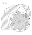
- Figure 6 which is a fragmentary cross-section of Figure 5 on plane VI-VI shows support surface 58 of the lateral wall 62 and an associated recessed bottom portion 68 of the same wall.
- the innermost support surface, i.e. support surface 58 , of the lateral wall 62 may be omitted since the remaining support surfaces 56 and 60 fully define an effective lateral support/restraint system. However, in most cases, a three-point or more accurately three-surface support geometry is preferred.
- the support surfaces lie on planes which are slanted in such a way as to match the slant of the insert lateral abutment surfaces 38, i.e., they make an angle with a normal to the base of the platform of the receiving pocket that is substantially equal to the angle ⁇ made by the insert lateral surfaces 38.
- the angles in Figure 6 have been exaggerated for clarity of exposition.
- a fresh receiving pocket is manufactured with tolerances for the abutment surfaces slanting angles such that upon initial assembly of an insert in its pertaining receiving pocket contact is initialized at an upper region of the support surface.
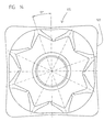
- FIG. 4 shows pocket 52 in which base 54 is substantially planar with a central threaded bore 72.
- Threaded bore 72 is very slightly off-set from the through bore 26 of the insert when the latter is seated in the receiving pocket firmly clamped with its clamping screw. This is to ensure that the abutment surfaces of the insert are biased against the corresponding support surfaces of the receiving pocket.
- Lateral wall 62 includes the previously mentioned support surfaces 56 and 58, recessed bottom portions 66 and 68, and a relief hollow 74.
- Lateral wall 64 includes support surface 60, a recessed bottom portion 70 and a relief hollow 76 .
- support surfaces 56, 58 and 60 are substantially flat, and can be taken to define planes of contact. It should be noted, however, that other forms of abutment surfaces such as, for example, a convex surface, may also be used. All the support surfaces are typically roughly equidistant from the central axis of the pocket.
- support surface 60 is typically perpendicular to surfaces 56 and 58 which are, themselves, typically coplanar.
- definition of"perpendicular" in this context is that the surfaces are at 90° to each other as viewed in a cross-section perpendicular to the axis of the pocket (itself corresponding to the axis of the insert when mounted in the pocket).
- support surfaces 58 and 60 are designed to support abutment surfaces 38 which are related by rotation by 90°, surface 58 is also related to surface 60 through rotation by 90°.
- Lateral relief hollows 74 and 76 must be configured to accommodate the ridges 36' and 36" of the insert (see Figure 5) not currently employed for locating the insert. This condition can be expressed in terms of the geometrical properties of pocket 52 , itself. Specifically, the opening of hollow 76 is formed such that a geometrical mapping of lateral support surface 60 by rotation through 45° about the axis of the pocket towards support surface 58 lies within hollow 76. Similarly, the opening of hollow 74 is formed such that a geometrical mapping of lateral support surface 58 by rotation through 45° about the axis of the pocket towards support surface 56 lies within hollow 74. In this context, it should be understood that the "support surface” referred to is the part of the surface configured so as to support the corresponding lateral abutment surfaces 38 of the insert.
- cutting insert 10 has been illustrated with eight indexable stations, as identified on the annular portion 22 of the upper face 12 by the corresponding roman numerals and as manifested by the use of eight rotational symmetric ridges. It should be appreciated, however, that the invention allows a considerably larger number of indexing stations.
- cutting insert 80 is similar to cutting insert 10 except that cutting insert 80 features a polygonal cutting edge 82 with eight indexable cutting edges 84 .
- the cutting edges are coordinated with an 8-ridged flank surface 86 , similar to ribbed flank surface 30 described above.
- the relief flank surface 88 in this case has a polygonal shape matching the cutting edge 82 and the tapered surface 90 of the transition surface portion is preferably frustro-pyramidal.
- the ridges of the flank surface may be rotated relative to the cutting edge geometry. In the example illustrated, a rotation of 15° has been introduced as can be seen most clearly in Figure 7D.
- the sets, or ''families", of interchangeable cutting inserts to be described must all have a number of indexing positions which is a multiple of some lowest-symmetry insert.
- one set could include 3-, 6-, 9- and even 11-fold symmetry, while another could include 5- and 10-fold symmetry.
- two cutting inserts from a set will be described as having n -fold and m ⁇ n -fold symmetry, respectively, where n is an integer greater than or equal to 3 and m is an integer greater than or equal to 2.
- cutting inserts 100 and 102 described here both have 4-fold rotational symmetry
- cutting inserts 10 and 80 both have 8-fold rotational symmetry.
- FIGS 8A-8F there is shown a first cutting insert, generally designated 100, having n -fold (in this case 4-fold) rotational symmetry. It is a particular feature of preferred implementations of cutting insert 100 that it is indexable exclusively at n indexing stations within an insert receiving pocket which is configured to receive alternately cutting inserts having both n -fold rotational symmetry and m ⁇ n -fold rotational symmetry, in this case, 4-fold and 8-fold rotational symmetry.
- cutting insert 100 has a unitary structure providing an upper surface 104 bounded by a cutting edge 106, a base 108, and a peripheral flank surface 110 .
- the peripheral flank surface is shaped such that an outline of a first cross-section taken through the lower part of the cutting insert perpendicular to its central axis 117 exhibits a recessed form which includes n corner portions 112 angularly spaced around the central axis so as to provide n -fold rotationally symmetric lateral abutment features, and support protrusions 114 protruding outwards from the peripheral flank surface between the corner portions.
- Support protrusions 114 are preferably shaped such that, under any geometrical mapping of an outline of corner portions 112 by rotation through an angle of less than 360°/ n about the central axis, the support protrusions extend beyond the outline.
- Figure 8E shows base 108 with the addition of four straight construction lines 118 joining between corner portions 112 .
- corner portions 112 equivalent to the flank ridges 36 described above, correspond substantially to corner regions of a regular polygon of n sides, in this case, a square.
- These corner portions provide abutment surfaces in a configuration equivalent to the abutment surfaces of inserts 10 and 80 described above, but with only 4-fold symmetry.
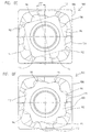
- Figure 10 shows the alignment of these abutment surfaces with the support surfaces of pocket 52 when the insert is inserted correctly.
- Figure 8F shows base 108 with the superposition of high symmetry lines 119 corresponding to the higher symmetry 8-ridged structure of the lower part of cutting inserts 10 and 80. Corner portions 112 correspond substantially to the ridge shapes, indicating that they are configured to provide equivalent abutment surfaces.
- Support protrusions 114 are configured to differ significantly from the ridge shape, thereby inhibiting incorrect indexing of the insert at intermediate positions. In a basic implementation, protrusions 114 can simply be omitted completely to provide a square base. Incorrect indexing is then quickly identified by a "loose" fit and complete lack of precision alignment. Preferably, however, support protrusions 114 are configured to provide additional support as near as possible to the cutting edge. Furthermore, in preferred implementations, protrusions 114 are configured to mechanically obstruct incorrect indexing of the insert within the pocket.
- protrusions 114 do not "fit" within the support surfaces of pocket 52.
- support protrusions 114 are preferably shaped such that, when an outline of corner portions 112 , corresponding to the ridges illustrated, is rotated through any angle less than the step between indexing positions, 90° in the case of 4-fold symmetry, some part of support protrusions 114 extends beyond the outline.
- This geometrical property ensures that, if the insert is placed at an incorrect angle in the pocket, it will not sit properly, thereby making the mistake self evident. In this sense, the insert design can be considered "fool proof'.
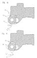
- Figure 12 shows the effect of an attempt to mount cutting insert 100 incorrectly within pocket 52 .
- the geometry of cutting edge 106 as defined by the outline of a cross-section taken through cutting insert 100 perpendicular to its central axis and proximal to upper surface 104 exhibits a non-recessed form.
- the cutting geometry is substantially square.
- the form of the cutting edge shown here is, in itself, conventional, each indexing station presenting a primary cutting edge at an entering angle K of substantially 90° and a secondary wiper edge 106' (see Figure 10).
- the "entering angle” as used herein in the description and claims is defined as the angle K formed between the primary cutting edge of the insert when mounted within a tool and the feed direction 116 of the tool.
- FIGS 9A-9F show a second cutting insert, generally designated 102, having n -fold (in this case 4-fold) rotational symmetry.
- Insert 102 is conceptually and structurally similar to insert 100 , equivalent features being designated similarly.
- Insert 102 differs from insert 100 in that it is modified to provide a substantially 45° entering angle.
- Figure 9E the orientation of corner portions 112 is rotated by 30° clockwise relative to the geometry of the primary cutting edges. This provides the required entering angle of substantially 45° when mounted in pocket 52, as shown in Figure 11.
- the effect of an attempt to mount cutting insert 102 incorrectly within pocket 52 is shown in Figure 13.
- insert 102 is, in itself, a conventional configuration for a 45° square insert.
- lateral relief hollows 74 and 76 must also be formed to accommodate support protrusions 114 of all members of the set of inserts with which pocket 52 is to be used.
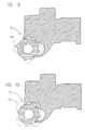
- Figure 14 illustrates a cutting insert 120 similar to cutting insert 100 described above, but with a recessed cutting edge 122 .
- Figures 15 and 16 show possible abutment geometry for sets of inserts with 3- and 6-fold symmetry, and 5- and 10-fold symmetry, respectively.
- the cutting geometry may be any desired cutting geometry of the appropriate symmetry.
- the base flank of the lower symmetry insert in each case may be either a regular configuration as shown, or a "fool proof" configuration having lateral support protrusions (not shown) functionally equivalent to protrusions 114 described above.
- each set of inserts may include more than two different levels of symmetry.
- pocket 52 described above may, with minimal adaptation, also be used for an insert with 11-fold symmetry.
Landscapes
- Engineering & Computer Science (AREA)
- Mechanical Engineering (AREA)
- Cutting Tools, Boring Holders, And Turrets (AREA)
- Milling Processes (AREA)
- Crystals, And After-Treatments Of Crystals (AREA)
- Processing Of Stones Or Stones Resemblance Materials (AREA)
- Harvester Elements (AREA)
- Knives (AREA)
- Perforating, Stamping-Out Or Severing By Means Other Than Cutting (AREA)
- Processing Of Terminals (AREA)
Abstract
Description
- The present invention relates to cutting tools and, in particular, it concerns a modular cutting tool assembly in which cutting inserts with different orders of rotational symmetry can be used alternately with a single tool holder.
- It is known to employ cutting inserts made of various hard materials which have round, polygonal, or otherwise rotationally symmetric cutting edges mounted in a receiving pocket of a tool holder of a cutting tool. During a machining operation (turning, milling, etc.), only a portion of the available cutting edge typically actually cuts the workpiece. The extent of this portion depends on the depth of cut. When a portion of an indexable cutting edge of a regular (e.g., polygonal) insert has been worked, the insert is indexed to present a whole new cutting edge.
- In the case of cutting inserts with polygonal cutting edges, proper operation can only be achieved by rotationally securing the insert within the pocket so as to withstand the cutting forces generated during use. Conventional teaching has relied on abutment surfaces resulting from the inherent polygonal shape of the cutting insert. However, especially in high torque applications, or in polygons with large numbers of sides, the inherent abutment geometry may prove inadequate to withstand torques which may result from cutting forces.
- Cutting inserts with round cutting edges exhibit rotational symmetry and could theoretically be continuously indexable in any angular position to accommodate actually observed wear. In practice, however, round inserts have also become restricted to use with a discrete number of indexing stations, angularly spaced by an equal shift angle. The angular shift between the indexing stations is referred to as the "angular pitch" of the insert.
- In order to make optimal use of a round cutting insert, it is desirable to prevent rotation of the insert from its indexed position during the cutting process, thereby limiting the wear to a defined portion of the cutting edge. This ensures that the portion of the cutting edge presented after repositioning is, in fact, un-used.
- A number of designs have been suggested for anchoring round inserts against rotation. These designs may be subdivided into two types, namely, "seat-pinning" and "lateral abutment". Examples of a seat-pinning design may be found in U.S. Patent No. 5,236,288 to Flueckiger and European Patent Publication No. 300,172 to Stashko. The lateral abutment design is exemplified by U.S. Patent No. 5,346,336 to Rescigno. All of these designs suffer from limited torque-resisting capability due to the poor size, location and orientation of the contact surfaces.
- From EP-A 0596843 representing the closest prior art a metal cutting insert is known. The insert comprises a top surface which is intersected by a frusto-conical edge surface to form therewith a round cutting edge. Five equidistantly spaced flat facets are formed in the edge surface. Upper ends of the facets are spaced below the cutting edge. The insert is fixed through a screw to a seat of a holder, such that two of the facets are pressed against respective flat contact areas formed on a locating surface of the holder.
- As will be clear from the above discussion, the requirements for effective restraining of a cutting insert are typically highly specific to the geometry of the cutting edge. Thus each type of insert, triangular, rectangular, square, or round, is provided with a dedicated tool holder design with a corresponding pocket shape. As a result, the use of multiple insert types is accompanied by the expense of providing and storing multiple tool holders, and necessitates the additional labor of exchanging the entire tool between cutting operations.
- In an attempt to reduce these costs and labor, modular systems based on replaceable cartridges have been developed. Examples of such systems include the "Modulmill" system commercially available from SANDVIK Coromant and the "NOVEX F 2010" system commercially available from Montanwerke Walter GmbH. These systems employ replaceable adapter cartridges each of which provides a pocket with clamping geometry suited to a specific cutting insert. Although these systems do allow the primary tool holder to be used with different cutting insert types, the replacement of the cartridges still adds a wasteful additional dissembly/assembly step to the changeover.
- There is therefore a need for a modular cutting tool assembly which allows alternate use of multiple cutting inserts with differing numbers of indexing positions within a single tool holder pocket. There is also a need for cutting inserts and tool holders for use in such an assembly.
- The present invention provides a modular cutting tool assembly in which cutting inserts with various differing numbers of indexing stations or differing cutting geometries can be used alternately in a generic tool holder pocket structure.
- According to one aspect of the present invention, the insert-receiving pocket is structured to provide circumscribing "three-point" locating and support features.
- According to a further aspect of the invention, a reduced-symmetry cutting insert is provided with protruding features which inhibit erroneous indexing of the insert in an improper angular position.
- The indexable inserts of the present invention may form part of a set of coordinated interchangeable inserts for use with a tool holder of a single size and shape. The inserts and receiving pockets of the invention are of great value in many applications including, but not limited to, milling cutters, broaches, turning tools and the like.
- In one embodiment, the present invention provides an indexable insert which has a plurality of discrete abutment surfaces, three of which are used at a time.
- According to the teachings of the present invention there is provided, a modular cutting tool assembly comprising: (a) a tool holder having at least one insert receiving pocket with a base and a plurality of lateral support surfaces; (b) a first cutting insert receivable within the pocket, the first cutting insert having an upper surface, a bottom surface and a peripheral flank surface, the peripheral flank surface being configured to provide abutment features with m×n-fold rotational symmetry about a central axis of the first cutting insert such that the first cutting insert can be restrained against the lateral support surfaces in any of m×n angular positions, for at least one value of each of n and m where n ≥ 3 and m ≥ 2; and (c) a second cutting insert receivable within the pocket, the second cutting insert having an upper surface, a bottom surface and a peripheral flank surface, the peripheral flank surface being configured to provide reduced-symmetry abutment features with only n-fold rotational symmetry about a central axis of the second cutting insert such that the second cutting insert can be restrained against the lateral support surfaces in only n angular positions, wherein the peripheral flank surface of the first cutting insert is configured such that a lower cross-section taken through the lower part of the first cutting insert perpendicular to the central axis exhibits a recessed form.
- According to a further feature of the present invention, the peripheral flank surface of the first cutting insert is configured such that an upper cross-section through the first cutting insert perpendicular to the central axis and proximal to the upper surface exhibits a non-recessed form.
- According to a further feature of the present invention, the upper cross-section corresponds to a substantially regular polygon with m×n sides.
- According to a further feature of the present invention, the upper cross-section is substantially circular.
- According to a further feature of the present invention, the peripheral flank surface of the second cutting insert is shaped such that a lower cross-section taken through the lower part of the second cutting insert perpendicular to the central axis at a point closer to the bottom surface exhibits a recessed form.
- According to a further feature of the present invention, the first entering angle differs from the second entering angle by about 180°/n.
- There is also provided according to the teachings of the present invention, a tool holder for alternately receiving a first cutting insert indexable in exactly n rotational positions and a second cutting insert indexable in m×n rotational positions, for at least one value of each of n and m where n ≥ 3 and m ≥ 2, the tool holder comprising at least one insert receiving pocket defined with reference to an axis passing through the pocket with which a central axis of the cutting inserts is to be aligned, the pocket having: (a) a base for supporting the cutting inserts; (b) first, second and third lateral support surfaces angularly spaced around, and substantially equidistant from, the axis; (c) a first lateral hollow located between the first and second lateral support surfaces; and (d) a second lateral hollow located between the second and third lateral support surfaces, wherein the first and second lateral hollows are formed such that geometrical mappings of the first and second lateral support surfaces by rotation through 360°/(m×n) about the axis lie within the first and second lateral hollows, respectively.
- According to a further feature of the present invention, the first, second and third lateral support surfaces define, respectively, first, second and third planes, the first plane being related to the second plane by a rotation through 360°/n about the axis.
- According to a further feature of the present invention, the second and third planes of the pocket are substantially coplanar.
- According to a further feature of the present invention, n = 4 and m = 2.
- There is also provided according to the teachings of the present invention, a cutting insert having n-fold rotational symmetry for some value of n where n ≥ 3, the cutting insert being indexable exclusively at n indexing stations within an insert receiving pocket which is configured to receive alternately cutting inserts having both n-fold rotational symmetry and m×n-fold rotational symmetry for some value of m where m ≥ 2, the cutting insert comprising a unitary structure having an upper surface bounded by a cutting edge, a base, a peripheral flank surface and a central axis, wherein the peripheral flank surface is shaped such that an outline of a first cross-section taken through the lower part of the cutting insert perpendicular to the central axis exhibits a recessed form including: (a) n corner portions angularly spaced around the central axis, the corner portions corresponding to n-fold rotationally symmetric lateral abutment features; and (b) support protrusions protruding outwards from the peripheral flank surface between the corner portions, wherein the support protrusions are shaped such that, under any geometrical mapping of an outline of the corner portions by rotation through an angle of less than 360°/n about the central axis, the support protrusions extend beyond the outline.
- According to a further feature of the present invention, the peripheral flank surface is further shaped such that an outline of a second cross-section taken through the cutting insert perpendicular to the central axis and proximal to the upper surface exhibits a non-recessed form.
- According to a further feature of the present invention, the corner portions correspond substantially to corner regions of a regular polygon of n sides.
- The invention is herein described, by way of example only, with reference to the accompanying drawings, wherein:
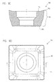
- FIG. 1A is a perspective view of a first preferred cutting insert, constructed and operative according to the teachings of the present invention, having a round cutting edge;
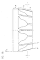
- FIG. 1B is a side view of the cutting insert of Figure 1A;
- FIG. 1C is a cross-sectional upward view taken along the line I-I of Figure 1B;
- FIG. 1D is a side cross-sectional view taken along the line II-II of Figure 1C;
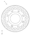
- FIG. 1E is a top view of the cutting insert of Figure 1A;
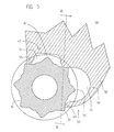
- FIG. 2A is a schematic representation of a geometric generating segment according to the teachings of the present invention showing the definitions of certain angles to be referred to in the description;
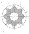
- FIG. 2B is a schematic representation of the geometry of a cross-section through a cutting insert constructed and operative according to the teachings of the present invention, the geometry being produced by rotational copying of the generating segment of Figure 2A;
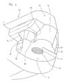
- FIG. 3 is a partially dissembled perspective view of a machine tool cutter, constructed and operative according to the teachings of the present invention, including four of the cutting inserts of Figure 1A mounted in pockets of a tool holder;
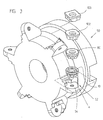
- FIG. 4 is an enlarged perspective view of one of the pockets of the tool holder of Figure 3;
- FIG. 5 is a horizontal cross-sectional view showing the abutment geometry of the cutting insert of Figure 1A in the pocket of Figure 4;
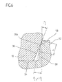
- FIG. 6 is a partial vertical cross-sectional view taken along the line VI-VI of Figure 5 showing a preferred geometry of contact between the cutting insert of Figure 1A and one of the support surfaces of the pocket of Figure 4;
- FIGS. 7A-7E are views similar to those of Figures 1A-1E, respectively, illustrating a second preferred cutting insert, constructed and operative according to the teachings of the present invention, having a polygonal cutting edge;
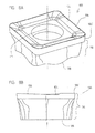
- FIG. 8A is a perspective view of a third preferred cutting insert, constructed and operative according to the teachings of the present invention, mountable within the pocket of Figure 4 in a reduced number of indexing positions;
- FIG. 8B is a side view of the cutting insert of Figure 8A;
- FIG. 8C is a side cross-sectional view of the cutting insert of Figure 8A;
- FIG. 8D is a top view of the cutting insert of Figure 8A;
- FIG. 8E is a bottom view of the cutting insert of Figure 8A with added construction lines to emphasize the geometry of lateral abutment surfaces of the insert;
- FIG. 8F is a view similar to Figure 8E with added construction lines to compare the geometry of lateral support protrusions of the insert with the high rotational symmetry features of the inserts of Figures 1 and 7;
- FIG. 9A is a perspective view of a fourth preferred cutting insert, constructed and operative according to the teachings of the present invention, mountable within the pocket of Figure 4 in a reduced number of indexing positions;
- FIG. 9B is a side view of the cutting insert of Figure 9A;
- FIG. 9C is a side cross-sectional view of the cutting insert of Figure 9A;
- FIG. 9D is a top view of the cutting insert of Figure 9A;
- FIG. 9E is a bottom view of the cutting insert of Figure 9A with added construction lines to emphasize the geometry of lateral abutment surfaces of the insert;
- FIG. 9F is a view similar to Figure 9E with added construction lines to compare the geometry of lateral support protrusions of the insert with the high rotational symmetry features of the inserts of Figures 1 and 7;
- FIGS. 10 and 11 are views similar to Figure 5 showing the abutment geometry and entering angle for the inserts of Figures 8A and 9A, respectively, when correctly mounted in the pocket of Figure 4;
- FIGS. 12 and 13 are views similar to Figures 10 and 11, respectively, showing the effect of attempts to position the inserts of Figures 8A and 9A incorrectly within the pocket of Figure4;
- FIG. 14 is a bottom view of a variation of the cutting insert of Figure 8A having a recessed cutting geometry;
- FIG. 15 is a schematic horizontal cross-sectional view showing the abutment geometry of a set of cutting inserts with triangular and hexagonal symmetry; and
- FIG. 16 is a schematic horizontal cross-sectional view showing the abutment geometry of a set of cutting inserts with pentagonal and decagonal symmetry.
-
- The present invention is a modular cutting tool assembly employing round and polygonal cutting inserts with peripheral flank surfaces shaped to provide abutment surfaces for opposing high torques, and corresponding insert-receiving pockets of tool holders. The geometry of the abutment surfaces enables the use of sets of inserts with differing numbers of indexing positions and differing entering angles within a given pocket geometry.
- The principles and operation of cutting tool assemblies, and their component cutting inserts and tool holders according to the present invention may be better understood with reference to the drawings and the accompanying description.
- Referring now to the drawings, Figures 1A-1E show a first cutting insert, generally designated 10, constructed and operative according to the teachings of the present invention.
- In general terms, cutting
insert 10 has anupper surface 12 bounded by acutting edge 14, abase 16, and aperipheral flank surface 18. The shape ofperipheral flank surface 18 varies along the height of cuttinginsert 10. Near the top ofperipheral flank surface 18, it conforms to the round or polygonal geometry of the cutting edge so as to provide support for cuttingedge 14. Lower down cuttinginsert 10,peripheral flank surface 18 is shaped to provide transverse abutment surfaces, preferably with recessed features such as channels, and in certain cases, as chevron-type channels. This latter possibility leads to a lower cross-sectional geometry which approximates to an n-pointed star. - The phrase "n-pointed star" as used in the specification and claims refers to a rotationally symmetric shape with n outermost points each of which is joined to its nearest neighbors by an inward pointing chevron or "V-shape". An example of a 5-pointed star is shown in Figure 2B. It should be noted that the lower peripheral flank surfaces of certain preferred cutting inserts of the present invention are described as having "approximately" or "substantially" n-pointed star geometry since the points and/or the chevron bases may be flattened, as will be described in more detail below.
- It should be appreciated that the present invention is applicable to a wide range of cutting inserts with rotationally-symmetric cutting edges. The term "rotationally-symmetric" is used herein in the description and claims to refer to shapes which are invariant under rotation through an angle of 360°/n where n is at least three. The term so defined includes regular polygons of three or more sides, whether straight-sided or made up of more complex combinations of straight or curved line segments. The term also includes circular shapes. Also included are variations on the above-mentioned shapes in which a repetitive pattern is superimposed over the basic shape. Examples of such patterns include serrations, and scalloped or wavy cutting edges. It will be noted that the symmetry of the inserts of the present invention, unless otherwise stated, is taken to refer to the symmetry of the abutment features. The cutting edge may exhibit equivalent or higher degrees of symmetry than the abutment surfaces.
- It should also be appreciated that neither rotational symmetry nor n-pointed star geometry imply symmetry under reflection. In cases in which a specific cutting application generates torque primarily in one direction, the structures of the present invention may be constructed asymmetrically with abutment surfaces for opposing the primary torque component. However, the invention will be illustrated by way of example in the context of symmetrical embodiments for opposing torques in both senses about the central axis.
- Reference will be made throughout the specification and claims to a central axis of an insert. The axis in question is the axis about which the cutting edge exhibits rotational symmetry. Reference is also made to the "top" and "bottom" of the insert. Wherever such references appear, the insert is assumed to be mounted with its base downwards so as to present its cutting edge upwards and with its axis vertical.
- The abutment surface geometry permits the use of these lower symmetry inserts within pockets also designed to receive higher symmetry cutting inserts, as will be described in more detail below.
- Reference is made in the description and claims to recessed and non-recessed shapes. It should be understood that the term "recess" is used in the description and claims to refer to a part of a shape or surface which is concave or otherwise generates a hollow. In more precise terms, a recess may be identified as any part of a shape or surface which lies interior to a virtual straight line connecting adjacent parts of the shape or surface. Conversely, a shape which at no point has a recess so defined is termed a "non-recessed" shape. Thus, the chevron of an n-pointed star constitutes a "recess" as herein defined, whereas a regular polygon is classified as a non-recessed shape.
- Turning now to the features of cutting
insert 10 in more detail, upper surface or rake 12 has, in this example, an inwardly slanted, peripheralannular portion 20, bordered at the outer perimeter thereof by cuttingedge 14, and a flat, innerannular portion 22, perpendicular to the axis of cuttinginsert 10. -
Upper surface 12 may also have additional chip control features such as a pattern of indentations or ridges. One such possibility is shown in Figure 1E. Again, it should be noted that the cutting insert is considered rotationally symmetric independent of the fact that the indices and various other features of the upper surface may not conform to this symmetry. - As can be best seen in Figure 1D, inner
annular portion 22 intersects at its inner extreme with acylindrical extension 24 of a central, standard so-called "partly cylindrical" bore 26, used for the passage of a standard counter-sunk clamping screw (not shown). It should be appreciated that the specific clamping technique employed to clamp cuttinginsert 10 within a tool holder does not, per se, constitute a part of the present invention, and that variations may be made in accordance with any other clamping technique without straying from the scope of the present invention. - Turning now to
peripheral flank surface 18, it is a particular feature of certain preferred cutting inserts of the present invention thatperipheral flank surface 18 is shaped such that a first cross-section taken through the cutting insert perpendicular to the central axis and proximal toupper surface 12 is bounded by a non-recessed form, whereas a second cross-section taken through the cutting insert perpendicular to the central axis at a point closer to base 16 exhibits n-fold rotational symmetry and includes recessed features for providing abutment surfaces for opposing torque about the central axis. - To this end,
peripheral flank surface 18 may be sub-divided along the height of cuttinginsert 10 into at least two, and typically three, portions. A first portion adjacent to cuttingedge 14 is denoted therelief flank surface 28 and has a non-recessed cross-sectional outline. The lower portion ofperipheral flank surface 18 constitutes aribbed flank surface 30.Ribbed flank surface 30 is preferably linked torelief flank surface 28 by a transitionflank surface portion 32 which provides a gradual transition between the two forms, as will be described below. These portions provide features having abutment surfaces for opposing torque about the central axis. -
Relief flank surface 28 typically corresponds to the geometry of the cutting edge employed. Thus, in cuttinginsert 10,relief flank surface 28 has a frustro-conical form, having a circular cross-section corresponding to the circular cutting edge illustrated. Thus,relief flank surface 28 may be described as having substantially constant cross-sectional geometry perpendicular to the central axis at all heights, although the dimensions of this geometry may vary somewhat with height.Relief flank surface 28 preferably extends downwards from cuttingedge 14 at least about a tenth of the height of cuttinginsert 10. -
Relief flank surface 28 is typically inclined at an acute angle ψ relative to the central axis of cuttinginsert 10. Angle ψ is commonly denoted the insert's "primary normal relief angle" and is preferably less than about 20° and typically about 7°. For a negative insert, ψ may be about 0° such thatrelief flank surface 28 is cylindrical. - Turning now to the features of ribbed
flank surface 30 in more detail, this is preferably implemented as a frustro-pyramidal ribbed surface withchannels 34 formed between projectingridges 36.Channels 34 preferably have a chevron-type cross-section. -
Ribbed flank surface 30 extends frombase 16 to a plane perpendicular to the insert axis indicated in Figure 1B as plane I-I.Ribbed flank surface 30 preferably extends for at least about an eighth, and typically for at least about a quarter, of the height of the cutting insert. Depending on the design oftransition flank surface 32, ribbedflank surface 30 may extend along the majority of the height ofperipheral flank surface 18. -
Ribbed flank surface 30 may be regarded as having "n"ridges 36 each having a crest which blends smoothly with a pair of planar, oppositely sloping, lateral abutment surfaces 38. At the junction of adjacent ridges, adjacent abutment surfaces 38 intersect at smoothedroot regions 40. The number of ridges is equal to the number of available indexing positions of the insert. For a circular cutting edge, n is preferably at least 5, and typically 8 or more. - Turning briefly to Figures 2A and 2B, these illustrate how the cross-section of
ribbed flank surface 30, shown here with n=5 may be considered an n-pointed star (Figure 2B) defined by rotationally copying n-1 times a concave chevron-shaped "generating segment" (Figure 2A) having symmetric legs on either side of a bisecting radius. The generating segment subtends a central pitch angle β equal to 360°/n. - As will discussed further below, it is a feature of certain preferred implementations of cutting
insert 10 that two spaced-apart abutment surfaces 38 are coplanar. In a simple example where n = 8, this may be achieved by ensuring that the symmetrical legs of the generating segment form angles γ relative to a bisecting radius equal to (90° - β/2°). The corresponding angle α is equal to (90° - β°). Thus, in this eight corner example illustrated, α = 45°, β = 45°, and γ = 67.5°. Where larger numbers of corners are employed, the coplanar surfaces may be two or more ridges apart. - It is a further feature of certain preferred implementations of cutting
insert 10 that the two spaced-apart abutment surfaces 38 have perpendicular intersections with a cross-section taken through cuttinginsert 10 perpendicular to its axis. The surfaces themselves may vary from perpendicular due to tapering ofribbed flank surface 30. However, for convenience of reference, such surfaces are referred to as "perpendicular abutment surfaces". This requirement may also be defined by simple geometrical conditions and, by way of example, is provided by the angles of the eight cornered insert listed above. Furthermore, the existence of at least some mutually perpendicular abutment surfaces follows immediately in any case in which n is a multiple of 4. - In a preferred case,
ribbed flank surface 30 is ideally frustro-pyramidal, meaning, among other things, that all the lateral abutment surfaces 38 form the same angle η relative to the axis of cuttinginsert 10, as indicated in Figure 1B. As a direct consequence, an imaginary straight line of intersection between pairs oflateral surfaces 38 associated with eachridge 36, passing through aligned corners of such ideally star-shaped polygonal contour sections as defined above, forms a corresponding angle ϕ with a normal to the base which is a function of both α and η, given by: ϕ = arc tan [sin(α) tan (η)]. The angle ϕ is larger than the relief angle ψ relating to the uppermost reliefflank surface portion 28. Given that the pressure angle α is less than 90°, it follows that ϕ>η. Naturally, all the ideally star-shaped polygonal contour sections are similar to one another, viz. can be obtained from one another by a mere change of scale. - Figure 1C shows
ribbed flank surface 30 in section on plane I-I of Figure 1B, i.e., at the junction betweenribbed flank surface 30 andtransition flank surface 32. It can be seen that the star-shaped polygonal contour ofribbed flank surface 30 is modified from the ideal shape in that theridges 36 androot regions 40 have been truncated and/or rounded out. In practice, all star-shaped polygonal contours on all horizontal planes of the lowermost body portion are typically identically modified, i.e., they haveridges 36 androot regions 40 which are truncated with the same width of filleted chamfers to produce ridges and root regions with constant widths, as seen in Figure 1B. Sinceridges 36 androot regions 40 have uniform widths along their respective length extents, they form the same angle ϕ with a normal to the base as the imaginary line of intersection between lateral abutment surfaces 38. - As the
root regions 40 are transformed into thetapered surfaces 42 with the onset of thetransition flank surface 32, the part of the star-shaped polygonal contours nearest to rootregion 40 is gradually lost. The geometry of abutment surfaces 38 near toridges 36, on the other hand, is maintained until the junction between transitionflank surface portion 32 andrelief flank surface 28 whereridges 36 themselves merge withrelief flank surface 28. - Transition
flank surface portion 32, itself, results from the superposition or union of a prolongation of the ribbed portion ofribbed flank surface 30 with atapered surface 42, best seen in Figure 1D. As a result, transitionflank surface portion 32 provides a gradual transition over which the depth of thechannels 34 inperipheral flank surface 18 are gradually reduced towardsrelief flank surface 28. Preferably, transitionflank surface portion 32 extends for at least about a third of the height of the cutting insert. - For powder metallurgy technological reasons, as well as for structural reasons, upper
relief flank surface 28 and cuttingedge 14 are preferably supported bytapered surfaces 42. The detailed shape of taperedsurfaces 42 may vary considerably. Preferred examples include frustro-conical (i.e., rounded) or frustro-pyramidal (i.e., flat surfaced) segments. - Turning now to Figures 3-6, there is shown a machine tool cutter or tool holder, generally designated 50, constructed and operative according to the teachings of the present invention, employing a number of cutting inserts 10 mounted in insert receiving pockets 52.
- Each
pocket 52 is formed with abase support surface 54 for supporting the base, and at least two, and preferably three, lateral support surfaces located for abutting angularly spaced abutment surfaces 38 provided by cuttinginsert 10. In the example illustrated here, these include afirst support surface 60, asecond support surface 58, and athird abutment surface 56. The combination of these lateral support surfaces provides a lateral support/restraint system structurally capable of resisting considerable torque. - The receiving pocket may be an integral part of the tool holder or an adapter part connected in any suitable way to the tool holder. In the latter case, a single tool holder may be made to receive, through a suitable range of adapters, a corresponding range of indexable inserts. As will be illustrated below, each pocket is itself able to accommodate a full set of inserts.
- Additional features of
pocket 52 are shown in the schematic sectional views of Figures 5 and 6.Pocket 52 has two generally perpendicular lateral walls, 62 and 64, with lateral support surfaces 56 and 58 integrally formed withwall 62 andsupport surface 60 integrally formed withwall 64. Support surfaces 56, 58, and 60 preferably do not extend all the way to thebase 54 of theinsert receiving pocket 52. At their lowermost border, the support surfaces meet in recessed bottom portions which are slanted away from the insert. By way of an example, Figure 6 which is a fragmentary cross-section of Figure 5 on plane VI-VI showssupport surface 58 of thelateral wall 62 and an associated recessedbottom portion 68 of the same wall. - It will be understood that the innermost support surface, i.e.
support surface 58, of thelateral wall 62 may be omitted since the remaining support surfaces 56 and 60 fully define an effective lateral support/restraint system. However, in most cases, a three-point or more accurately three-surface support geometry is preferred. - As also exemplified in Figure 6, the support surfaces lie on planes which are slanted in such a way as to match the slant of the insert lateral abutment surfaces 38, i.e., they make an angle with a normal to the base of the platform of the receiving pocket that is substantially equal to the angle η made by the insert lateral surfaces 38. It should be noted that the angles in Figure 6 have been exaggerated for clarity of exposition. A fresh receiving pocket is manufactured with tolerances for the abutment surfaces slanting angles such that upon initial assembly of an insert in its pertaining receiving pocket contact is initialized at an upper region of the support surface. Upon plastic deformation of this surface, during mostly the initial clamping, contact spreads from the upper region and gradually encompasses the entire area of the support surface. In this way an
abutment surface 38a corresponding to the "foot-print" of the abutment surface is established, in the form of a band of depth "b" corresponding to the depth of the abutment surface, on the juxtaposed pertaininglateral surface 38 towards the top of theribbed flank surface 30 and extending by about b/2 into thetransition surface portion 32. - Turning now to a number of additional features of
tool holder 50, Figure 4 showspocket 52 in which base 54 is substantially planar with a central threaded bore 72. Threaded bore 72 is very slightly off-set from the throughbore 26 of the insert when the latter is seated in the receiving pocket firmly clamped with its clamping screw. This is to ensure that the abutment surfaces of the insert are biased against the corresponding support surfaces of the receiving pocket. -
Lateral wall 62 includes the previously mentioned support surfaces 56 and 58, recessedbottom portions Lateral wall 64 includessupport surface 60, a recessedbottom portion 70 and a relief hollow 76. Typically, support surfaces 56, 58 and 60 are substantially flat, and can be taken to define planes of contact. It should be noted, however, that other forms of abutment surfaces such as, for example, a convex surface, may also be used. All the support surfaces are typically roughly equidistant from the central axis of the pocket. - Corresponding to the geometry of abutment surfaces 38 described above,
support surface 60 is typically perpendicular tosurfaces surface 58 is also related tosurface 60 through rotation by 90°. - Lateral relief hollows 74 and 76 must be configured to accommodate the
ridges 36' and 36" of the insert (see Figure 5) not currently employed for locating the insert. This condition can be expressed in terms of the geometrical properties ofpocket 52, itself. Specifically, the opening of hollow 76 is formed such that a geometrical mapping oflateral support surface 60 by rotation through 45° about the axis of the pocket towardssupport surface 58 lies within hollow 76. Similarly, the opening of hollow 74 is formed such that a geometrical mapping oflateral support surface 58 by rotation through 45° about the axis of the pocket towardssupport surface 56 lies within hollow 74. In this context, it should be understood that the "support surface" referred to is the part of the surface configured so as to support the corresponding lateral abutment surfaces 38 of the insert. - Referring to Figure 1A, cutting
insert 10 has been illustrated with eight indexable stations, as identified on theannular portion 22 of theupper face 12 by the corresponding roman numerals and as manifested by the use of eight rotational symmetric ridges. It should be appreciated, however, that the invention allows a considerably larger number of indexing stations. - Turning now to Figures 7A-7E, a second form of cutting insert, generally designated 80, constructed and operative according to the teachings of the present invention, is shown. Generally speaking, cutting
insert 80 is similar to cuttinginsert 10 except that cuttinginsert 80 features apolygonal cutting edge 82 with eight indexable cutting edges 84. The cutting edges are coordinated with an 8-ridgedflank surface 86, similar toribbed flank surface 30 described above. - Clearly, as seen in Figure 7A, the
relief flank surface 88 in this case has a polygonal shape matching thecutting edge 82 and the taperedsurface 90 of the transition surface portion is preferably frustro-pyramidal. Optionally, depending on the preferred geometry of the pocket support surfaces, the ridges of the flank surface may be rotated relative to the cutting edge geometry. In the example illustrated, a rotation of 15° has been introduced as can be seen most clearly in Figure 7D. - Turning now to further features of the present invention, it has been found that the abutment geometry described thus far can be used to advantage as the basis for a modular cutting tool assembly. It will already be apparent that cutting
insert 80 can be used interchangeably with cuttinginsert 10 withinpocket 52, thereby serving as two members of a modular set of interchangeable cutting inserts. In addition to these, a preferred implementation of the present invention also provides a cutting tool assembly with interchangeable inserts having differing numbers of indexing positions and differing entering angles for different machining applications. These and other features will now be illustrated with reference to Figures 8-13 through description of twoadditional inserts - Before addressing the remaining Figures directly, it will be helpful to clarify certain terminology to be used in the remainder of this description, as well as in the claims. Up until this point, reference has been made to individual cutting inserts with a given order of rotational symmetry corresponding to a given number of indexing positions. For ease of exposition, this has been referred to as "n-fold symmetry". At this point, however, it will be necessary to distinguish between interchangeable cutting inserts having differing orders of rotational symmetry, corresponding to differing numbers of indexing positions.
- The sets, or ''families", of interchangeable cutting inserts to be described must all have a number of indexing positions which is a multiple of some lowest-symmetry insert. Thus, one set could include 3-, 6-, 9- and even 11-fold symmetry, while another could include 5- and 10-fold symmetry. For generality of reference, two cutting inserts from a set will be described as having n-fold and m×n-fold symmetry, respectively, where n is an integer greater than or equal to 3 and m is an integer greater than or equal to 2.
- By way of example, cutting
inserts - Turning now to Figures 8A-8F, there is shown a first cutting insert, generally designated 100, having n-fold (in this case 4-fold) rotational symmetry. It is a particular feature of preferred implementations of cutting
insert 100 that it is indexable exclusively at n indexing stations within an insert receiving pocket which is configured to receive alternately cutting inserts having both n-fold rotational symmetry and m×n-fold rotational symmetry, in this case, 4-fold and 8-fold rotational symmetry. - Generally speaking, cutting
insert 100 has a unitary structure providing anupper surface 104 bounded by acutting edge 106, abase 108, and aperipheral flank surface 110. The peripheral flank surface is shaped such that an outline of a first cross-section taken through the lower part of the cutting insert perpendicular to itscentral axis 117 exhibits a recessed form which includesn corner portions 112 angularly spaced around the central axis so as to provide n-fold rotationally symmetric lateral abutment features, andsupport protrusions 114 protruding outwards from the peripheral flank surface between the corner portions.Support protrusions 114 are preferably shaped such that, under any geometrical mapping of an outline ofcorner portions 112 by rotation through an angle of less than 360°/n about the central axis, the support protrusions extend beyond the outline. - These geometrical relationships will be better understood with reference particularly to Figures 8E and 8F. Both of these Figures show similar bottom views of cutting
insert 100, but have different construction lines added for convenience of exposition. Parenthetically, it should be noted that, in the examples shown here, the required geometry appears in the lower portion of the insert and continues to thebase 108. As a result, the bottom view can be used to illustrate the features of the required geometry. In the general case, these features need not necessarily extend to the base. However, equivalent features will be present in a cross-sectional view taken at some point in the lower part of the insert. The words "lower part" in this context are taken to refer to the lower 70%, and typically, the lower half, of the insert. - Figure 8E shows
base 108 with the addition of fourstraight construction lines 118 joining betweencorner portions 112. Here, it can be seen thatcorner portions 112, equivalent to theflank ridges 36 described above, correspond substantially to corner regions of a regular polygon of n sides, in this case, a square. These corner portions provide abutment surfaces in a configuration equivalent to the abutment surfaces ofinserts pocket 52 when the insert is inserted correctly. - Figure 8F shows
base 108 with the superposition ofhigh symmetry lines 119 corresponding to the higher symmetry 8-ridged structure of the lower part of cutting inserts 10 and 80.Corner portions 112 correspond substantially to the ridge shapes, indicating that they are configured to provide equivalent abutment surfaces.Support protrusions 114, on the other hand, are configured to differ significantly from the ridge shape, thereby inhibiting incorrect indexing of the insert at intermediate positions. In a basic implementation,protrusions 114 can simply be omitted completely to provide a square base. Incorrect indexing is then quickly identified by a "loose" fit and complete lack of precision alignment. Preferably, however,support protrusions 114 are configured to provide additional support as near as possible to the cutting edge. Furthermore, in preferred implementations,protrusions 114 are configured to mechanically obstruct incorrect indexing of the insert within the pocket. - The criteria for the aforementioned mechanical obstruction are that
protrusions 114 do not "fit" within the support surfaces ofpocket 52. In a more precise formulation,support protrusions 114 are preferably shaped such that, when an outline ofcorner portions 112, corresponding to the ridges illustrated, is rotated through any angle less than the step between indexing positions, 90° in the case of 4-fold symmetry, some part ofsupport protrusions 114 extends beyond the outline. This geometrical property ensures that, if the insert is placed at an incorrect angle in the pocket, it will not sit properly, thereby making the mistake self evident. In this sense, the insert design can be considered "fool proof'. Figure 12 shows the effect of an attempt to mount cuttinginsert 100 incorrectly withinpocket 52. - Typically, although not necessarily. the geometry of cutting
edge 106 as defined by the outline of a cross-section taken through cuttinginsert 100 perpendicular to its central axis and proximal toupper surface 104 exhibits a non-recessed form. In this example, the cutting geometry is substantially square. The form of the cutting edge shown here is, in itself, conventional, each indexing station presenting a primary cutting edge at an entering angle K of substantially 90° and a secondary wiper edge 106' (see Figure 10). The "entering angle" as used herein in the description and claims is defined as the angle K formed between the primary cutting edge of the insert when mounted within a tool and thefeed direction 116 of the tool. - Turning now to Figures 9A-9F, these show a second cutting insert, generally designated 102, having n-fold (in this case 4-fold) rotational symmetry.
Insert 102 is conceptually and structurally similar to insert 100, equivalent features being designated similarly.Insert 102 differs frominsert 100 in that it is modified to provide a substantially 45° entering angle. Thus, as seen in Figure 9E, the orientation ofcorner portions 112 is rotated by 30° clockwise relative to the geometry of the primary cutting edges. This provides the required entering angle of substantially 45° when mounted inpocket 52, as shown in Figure 11. The effect of an attempt to mount cuttinginsert 102 incorrectly withinpocket 52 is shown in Figure 13. - Here too, the cutting geometry of
insert 102 is, in itself, a conventional configuration for a 45° square insert. - At this stage, it will be clear that the features of cutting
inserts pocket 52. Specifically, lateral relief hollows 74 and 76 must also be formed to accommodatesupport protrusions 114 of all members of the set of inserts with whichpocket 52 is to be used. - It should be clear that the cutting tool assemblies of the present invention are not limited to cutting inserts with non-recessed cutting geometry. By way of example, Figure 14 illustrates a cutting
insert 120 similar to cuttinginsert 100 described above, but with a recessedcutting edge 122. - As mentioned earlier, it is important to appreciate that the principles of the modular cutting insert assembly and corresponding pockets and cutting inserts of the present invention are not limited to the 4-fold and 8-fold symmetry set illustrated. By way of schematic illustration, Figures 15 and 16 show possible abutment geometry for sets of inserts with 3- and 6-fold symmetry, and 5- and 10-fold symmetry, respectively. In each case, the cutting geometry may be any desired cutting geometry of the appropriate symmetry. The base flank of the lower symmetry insert in each case may be either a regular configuration as shown, or a "fool proof" configuration having lateral support protrusions (not shown) functionally equivalent to
protrusions 114 described above. - It should also be noted that each set of inserts may include more than two different levels of symmetry. For example,
pocket 52 described above may, with minimal adaptation, also be used for an insert with 11-fold symmetry. - While the invention has been described by way of illustration with reference to certain specific embodiments, it will be understood that the embodiment and variations discussed are merely exemplary and that the invention may be carried out with many other mechanical modifications and adaptations, without departing from the scope of the claims.
Claims (23)
- A tool holder for alternately receiving a first cutting insert (100, 102, 120) indexable in exactly n rotational positions and a second cutting insert (10, 80) indexable in m×n rotational positions, for at least one value of each of n and m where n ≥ 3 and m ≥ 2, the tool holder comprising at least one insert receiving pocket (52) defined with reference to an axis passing through said pocket with which a central axis of the cutting inserts is to be aligned, said pocket having:wherein said first and second lateral hollows are formed such that geometrical mappings of said first and second lateral support surfaces by rotation through 360°/(m×n) about said axis lie within said first and second lateral hollows, respectively.(a) a base (54) for supporting the cutting inserts;(b) first (60), second (58) and third (56) lateral support surfaces angularly spaced around, and substantially equidistant from, said axis;(c) a first lateral hollow (76) located between said first and second lateral support surfaces; and(d) a second lateral hollow (74) located between said second and third lateral support surfaces,
- The tool holder of claim 1, wherein said first, second and third lateral support surfaces (60, 58, 56) define, respectively, first, second and third planes, said first plane being related to said second plane by a rotation through 360°/n about said axis.
- The tool holder of claim 2, wherein said second and third planes of said pocket (52) are substantially coplanar.
- The tool holder of claim 1, wherein n = 4 and m = 2.
- A cutting insert (100, 102, 120) having n-fold rotational symmetry for some value of n where n ≥ 3, the cutting insert being indexable exclusively at n indexing stations within an insert receiving pocket (52) which is configured to receive alternately cutting inserts having both n-fold rotational symmetry and m×n-fold rotational symmetry for some value of m where m ≥ 2, the cutting insert comprising a unitary structure having an upper surface bounded by a cutting edge, a base, a peripheral flank surface (110) and a central axis (117), wherein said peripheral flank surface is shaped such that an outline of a first cross-section taken through the lower part of the cutting insert perpendicular to said central axis exhibits a recessed form including:wherein said support protrusions are shaped such that, under any geometrical mapping of an outline of said corner portions by rotation through an angle of less than 360°/n about said central axis, said support protrusions extend beyond said outline.(a) n corner portions (112) angularly spaced around said central axis, said corner portions corresponding to n-fold rotationally symmetric lateral abutment features; and(b) support protrusions (114) protruding outwards from said peripheral flank surface between said corner portions.
- The cutting insert of claim 5, wherein said peripheral flank surface (110) is further shaped such that an outline of a second cross-section taken through the cutting insert perpendicular to said central axis and proximal to said upper surface exhibits a non-recessed form.
- The cutting insert of claim 5, wherein said corner portions correspond substantially to corner regions of a regular polygon of n sides.
- The cutting insert of claim 5, wherein said peripheral flank surface is further shaped such that an outline of a second cross-section taken through the cutting insert perpendicular to said central axis and proximal to said upper surface exhibits a recessed form.
- The cutting insert of claim 5, wherein n = 4 and m = 2.
- A modular cutting tool assembly comprising:(a) the cutting insert of claim 5; and(b) a tool holder (50) having at least one insert receiving pocket (52) for receiving the cutting insert, said pocket including:(i) a base (54) for supporting the cutting insert;(ii) first (60), second (58) and third (56) lateral support surfaces configured for abutting a corresponding three of said lateral abutment features of the cutting insert;(iii) a first lateral hollow (76) located between said first and second lateral support surfaces for accommodating a first of said support protrusions; and(iv) a second lateral hollow (74) located between said second and third lateral support surfaces for accommodating a second of said support protrusions.
- A modular cutting tool assembly comprising:wherein said peripheral flank surface (18) of said first cutting insert (10, 80) is configured such that a lower cross-section taken through the lower part of said first cutting insert perpendicular to said central axis exhibits a recessed form.(a) a tool holder (50) having at least one insert receiving pocket (52) with a base (54) and a plurality of lateral support surfaces;(b) a first cutting insert (10, 80) receivable within said pocket (52), said first cutting insert having an upper surface (12), a bottom surface (16) and a peripheral flank surface (18), said peripheral flank surface being configured to provide abutment features with m×n-fold rotational symmetry about a central axis of said first cutting insert such that said first cutting insert can be restrained against said lateral - support surfaces in any of m×n angular positions, for at least one value of each of n and m where n ≥ 3 and m ≥ 2; and(c) a second cutting insert (100, 102, 120) receivable within said pocket (52), said second cutting insert having an upper surface (104), a bottom surface (108) and a peripheral flank surface (110), said peripheral flank surface being configured to provide reduced-symmetry abutment features with only n-fold rotational symmetry about a central axis of said second cutting insert such that said second cutting insert can be restrained against said lateral support surfaces in only n angular positions,
- The modular cutting tool assembly of claim 11, wherein said peripheral flank surface (18) of said first cutting insert (10, 80) is configured such that an upper cross-section through said first cutting insert perpendicular to said central axis and proximal to said upper surface exhibits a non-recessed form.
- The modular cutting tool assembly of claim 12, wherein said upper cross-section corresponds to a substantially regular polygon with m×n sides.
- The modular cutting tool assembly of claim 12, wherein said upper cross-section is substantially circular.
- The modular cutting tool assembly of claim 11, wherein said peripheral flank surface (18) of said first cutting insert (10, 80) is configured such that an upper cross-section through said first cutting insert perpendicular to said central axis and proximal to said upper surface exhibits a recessed form.
- The modular cutting tool assembly of claim 11, wherein said peripheral flank surface (110) of said second cutting insert (100, 102, 120) is shaped such that a lower cross-section taken through the lower part of said second cutting insert perpendicular to said central axis at a point closer to said bottom surface exhibits a recessed form.
- The modular cutting tool assembly of claim 16, wherein said lower cross-section of said second cutting insert (100, 102, 120) includes:said support protrusions being shaped such that, under any geometrical mapping of an outline of said corner portions by rotation through an angle of less than 360°/n about said central axis, said support protrusions extend beyond said outline.(a) n corner portions angularly spaced around said central axis, said corner portions corresponding to n-fold rotationally symmetric lateral abutment features; and(b) support protrusions protruding outwards from said peripheral flank surface between said corner portions,
- The modular cutting tool assembly of claim 17, wherein said corner portions correspond substantially to corner regions of a regular polygon of n sides.
- The modular cutting tool assembly of claim 16, wherein said peripheral flank surface (110) of said second cutting insert (100, 102, 120) is shaped such that an upper cross-section taken through said second cutting insert perpendicular to said central axis and proximal to said upper surface exhibits a non-recessed form.
- The modular cutting tool assembly of claim 11, wherein said plurality of lateral support surfaces of said pocket include first (60), second (58) and third (56) lateral support surfaces, said lateral support surfaces being angularly spaced around, and substantially equidistant from, a central axis of said pocket, said pocket further including:wherein said first and second lateral hollows are formed such that geometrical mappings of said first and second lateral support surfaces by rotation through 360°/(m×n) about said axis lie within said first and second lateral hollows, respectively.(a) a first lateral hollow (76) located between said first and second lateral support surfaces; and(b) a second lateral (74) hollow located between said second and third lateral support surfaces,
- The modular cutting tool assembly of claim 20, wherein said first, second and third lateral support surfaces define, respectively, first, second and third planes, said first plane being related to said second plane by a rotation through 360°/n about said axis.
- The modular cutting tool assembly of claim 21, wherein said second and third planes are substantially coplanar.
- The modular cutting tool assembly of claim 11, wherein n = 4 and m = 2.
Applications Claiming Priority (3)
| Application Number | Priority Date | Filing Date | Title |
|---|---|---|---|
| IL11984196 | 1996-12-16 | ||
| IL11984196A IL119841A (en) | 1996-12-16 | 1996-12-16 | Cutting inserts |
| PCT/IL1997/000412 WO1998026893A1 (en) | 1996-12-16 | 1997-12-16 | Modular cutting tool assembly |
Publications (2)
| Publication Number | Publication Date |
|---|---|
| EP0944451A1 EP0944451A1 (en) | 1999-09-29 |
| EP0944451B1 true EP0944451B1 (en) | 2003-02-26 |
Family
ID=11069589
Family Applications (2)
| Application Number | Title | Priority Date | Filing Date |
|---|---|---|---|
| EP97935738A Expired - Lifetime EP0964763B1 (en) | 1996-12-16 | 1997-08-26 | Cutting inserts |
| EP97947851A Expired - Lifetime EP0944451B1 (en) | 1996-12-16 | 1997-12-16 | Modular cutting tool assembly |
Family Applications Before (1)
| Application Number | Title | Priority Date | Filing Date |
|---|---|---|---|
| EP97935738A Expired - Lifetime EP0964763B1 (en) | 1996-12-16 | 1997-08-26 | Cutting inserts |
Country Status (22)
| Country | Link |
|---|---|
| US (2) | US6164878A (en) |
| EP (2) | EP0964763B1 (en) |
| JP (3) | JP3830977B2 (en) |
| KR (2) | KR100481245B1 (en) |
| CN (1) | CN1088416C (en) |
| AR (1) | AR010577A1 (en) |
| AT (1) | ATE233145T1 (en) |
| AU (2) | AU3862297A (en) |
| BR (2) | BR9714028A (en) |
| CA (2) | CA2274480C (en) |
| CZ (2) | CZ295077B6 (en) |
| DE (3) | DE69731404T2 (en) |
| HU (2) | HU223291B1 (en) |
| IL (1) | IL119841A (en) |
| NO (2) | NO992443D0 (en) |
| NZ (1) | NZ335788A (en) |
| PL (1) | PL184720B1 (en) |
| RU (1) | RU2186661C2 (en) |
| TR (1) | TR199901884T2 (en) |
| TW (2) | TW334367B (en) |
| WO (2) | WO1998026892A1 (en) |
| ZA (1) | ZA978755B (en) |
Families Citing this family (100)
| Publication number | Priority date | Publication date | Assignee | Title |
|---|---|---|---|---|
| US6238133B1 (en) * | 1998-10-20 | 2001-05-29 | Kennametal Pc Inc. | Anti-rotation mounting mechanism for round cutting insert |
| AT3111U1 (en) * | 1998-12-22 | 1999-10-25 | Plansee Tizit Gmbh | CUTTING TOOL |
| US8201598B2 (en) | 2000-07-19 | 2012-06-19 | Green Kevin J | Cutting tool for use with a stump cutting apparatus |
| US6508612B1 (en) * | 2000-09-05 | 2003-01-21 | Kennametal Inc. | Milling cutter capable of using inserts of various geometrical shapes |
| DE10128329A1 (en) * | 2001-06-12 | 2002-12-19 | Frank Leonhardt | Method for operating cutting head with reversible cutting plates involves fixing plates on head so that both left and right halves of cutting edges can be used during finishing process on workpiece |
| IL145574A0 (en) * | 2001-09-24 | 2002-06-30 | Iscar Ltd | Cutting tool and cutting insert therefor |
| IL150783A0 (en) * | 2001-10-16 | 2003-02-12 | Iscar Ltd | Cutting tool and cutting insert therefor |
| SE521579C2 (en) * | 2002-03-21 | 2003-11-11 | Sandvik Ab | Tools and cutting tools for chip separating machining |
| GB2388063B (en) * | 2002-04-23 | 2005-11-23 | Emhart Llc | Improved blind rivet |
| US6811359B2 (en) * | 2002-05-31 | 2004-11-02 | Kennametal Inc. | True helical cutter system |
| IL150015A (en) * | 2002-06-04 | 2007-06-17 | Amir Satran | Cutting insert and milling cutter |
| DE10228503A1 (en) * | 2002-06-21 | 2004-01-15 | MAPAL Fabrik für Präzisionswerkzeuge Dr. Kress KG | Tool for machining valve seats |
| DE10234346A1 (en) * | 2002-07-26 | 2004-02-05 | Komet Präzisionswerkzeuge Robert Breuning Gmbh | Tool head with at least two indexable inserts |
| FR2847838B1 (en) * | 2002-12-02 | 2006-01-06 | Safety | HEAVY CUTTING PLATE |
| SE525913C2 (en) * | 2002-12-20 | 2005-05-24 | Seco Tools Ab | Cutter, tool and method of mounting the insert where the insert can be oriented in the desired position |
| US7722297B2 (en) * | 2003-04-15 | 2010-05-25 | Tdy Industries, Inc. | Antirotation tool holder and cutting insert |
| US7220083B2 (en) * | 2003-10-15 | 2007-05-22 | Tdy Industries, Inc. | Cutting insert for high feed face milling |
| DE102004046425A1 (en) * | 2004-09-24 | 2006-04-06 | Universität Kassel | Internal form working tool has shaft and working head with multiple shapings having smooth transition to shoulder |
| US7789598B2 (en) * | 2005-07-12 | 2010-09-07 | Kyocera Corporation | Surface coated cutting tool |
| JP4810903B2 (en) * | 2005-07-15 | 2011-11-09 | 株式会社タンガロイ | Turning tools and high feed inserts |
| SE530181C2 (en) * | 2005-12-21 | 2008-03-18 | Sandvik Intellectual Property | Tools for chip separating machining and basic body and separate locking means for this |
| DE102006011581B4 (en) * | 2006-03-10 | 2016-04-28 | Kennametal Widia Produktions Gmbh & Co. Kg | Cutting insert and milling tool |
| US7476062B2 (en) * | 2006-05-08 | 2009-01-13 | Kennametal Inc. | Cutting insert with recessed corners |
| US7429150B2 (en) * | 2006-05-31 | 2008-09-30 | Kennametal Inc. | Tool holder with spherical contact points |
| DE102006028729A1 (en) * | 2006-06-20 | 2007-12-27 | Komet Group Holding Gmbh | Machine tool and cutting ring for a machine tool |
| DE102006035182A1 (en) * | 2006-07-29 | 2008-01-31 | Hartmetall-Werkzeugfabrik Paul Horn Gmbh | Tool system, has cutting blade protruding over holder, where holder is provided with supporting part protruding towards projection of cutting blade and forming supporting surface for partial attachment of cutting tool |
| WO2008109690A1 (en) * | 2007-03-05 | 2008-09-12 | Mori Seiki Usa, Inc. | Device and method for turning in virtual planes |
| US7458753B1 (en) * | 2007-06-25 | 2008-12-02 | Kennametal Inc. | Round cutting insert with chip control feature |
| JP4738391B2 (en) * | 2007-09-10 | 2011-08-03 | 京セラ株式会社 | Throw away tip and rotary tool using the same |
| IL192785A0 (en) * | 2007-10-22 | 2009-02-11 | Gershon Harif | Cutting tool with protrusions, and methods of use thereof |
| US7905689B2 (en) * | 2008-05-07 | 2011-03-15 | Tdy Industries, Inc. | Cutting tool system, cutting insert, and tool holder |
| KR101549718B1 (en) * | 2008-06-26 | 2015-09-02 | 쎄코 툴스 에이비 | Family of cutting inserts, milling cutting tool, and cutting insert background and summary |
| DE102008037915B3 (en) * | 2008-08-14 | 2009-08-13 | Kennametal Inc. | Indexable insert |
| US8454277B2 (en) * | 2008-12-18 | 2013-06-04 | Kennametal Inc. | Toolholder and toolholder assembly with elongated seating pads |
| SE533249C2 (en) * | 2009-03-06 | 2010-07-27 | Seco Tools Ab | Cut with recessed cutting support surface and cutting tools |
| US9586264B2 (en) | 2009-04-28 | 2017-03-07 | Kennametal Inc. | Double-sided cutting insert for drilling tool |
| SE534506C2 (en) * | 2009-04-30 | 2011-09-13 | Seco Tools Ab | Cutting tool and a cutting holder for a cutting tool |
| KR101103216B1 (en) | 2009-05-19 | 2012-01-05 | 대구텍 유한회사 | Double-sided cutting insert with circular shape and cutting tool using the same |
| USD676072S1 (en) | 2009-06-19 | 2013-02-12 | Republic Machine, Inc. | Cutting tool |
| US7959099B1 (en) | 2009-06-19 | 2011-06-14 | Cox William W | Bolt-in toolholder for a rotor assembly |
| US8740121B1 (en) | 2009-06-19 | 2014-06-03 | Republic Machine, Inc. | Rotary grinder/shredder |
| USD676071S1 (en) | 2009-06-19 | 2013-02-12 | Republic Machine, Inc. | Cutting tool |
| GB2474280A (en) * | 2009-10-09 | 2011-04-13 | Cutting & Wear Resistant Dev | Cutting tool insert with ridges and troughs |
| US8573903B2 (en) | 2009-11-03 | 2013-11-05 | Kennametal Inc. | Round cutting insert with anti-rotation feature |
| US8807884B2 (en) * | 2009-12-18 | 2014-08-19 | Kennametal Inc. | Tool holder for multiple differently-shaped cutting inserts |
| US8388274B2 (en) * | 2010-01-06 | 2013-03-05 | Kennametal Inc. | Round cutting insert with asymmetric chipbreaker feature |
| SE534651C2 (en) * | 2010-02-12 | 2011-11-08 | Sandvik Intellectual Property | Cutting, tool part, procedure and machine tool for chip cutting metal machining |
| RU2012138428A (en) * | 2010-03-10 | 2014-04-20 | Тунгалой Корпорейшн | CUTTING PLATE AND CUTTING TOOL |
| JP5185322B2 (en) * | 2010-05-26 | 2013-04-17 | 住友電工ハードメタル株式会社 | Cutting tools |
| RU2013113622A (en) * | 2010-09-30 | 2014-11-10 | Тунгалой Корпорейшн | CUTTING TOOL WITH REPLACEABLE CUTTING EDGE |
| RU2568227C2 (en) * | 2010-11-03 | 2015-11-10 | Секо Тулз Аб | Cutting plate with grooved surface forming multiple bearing surfaces |
| EP2450140B1 (en) * | 2010-11-03 | 2013-01-09 | SECO TOOLS AB (publ) | Tool for holding a plurality of types of cutting inserts |
| EP2455172B1 (en) * | 2010-11-19 | 2013-01-16 | SECO TOOLS AB (publ) | Cutting insert with evolutive wedge or clearance angle and toolholder using such a cutting insert |
| US8657539B2 (en) | 2011-03-28 | 2014-02-25 | Kennametal Inc. | Round cutting insert with reverse anti-rotation feature |
| USD658218S1 (en) | 2011-03-28 | 2012-04-24 | Kennametal Inc. | Round cutting insert with reverse anti-rotation feature |
| WO2013000729A1 (en) * | 2011-06-27 | 2013-01-03 | Walter Ag | Cubic cutting insert for boring or plunging |
| AT12672U1 (en) * | 2011-09-15 | 2012-09-15 | Ceratizit Luxembourg S Ar L | SET OF CUTTING INSERTS AND MILLING TOOL HOLDER |
| US8882402B2 (en) | 2011-11-22 | 2014-11-11 | Kennametal Inc. | Anti-rotation mounting mechanism for a round insert |
| US8647026B2 (en) * | 2011-11-23 | 2014-02-11 | Kennametal Inc. | Cutting tool with pocket feature for reducing stress |
| US9475134B2 (en) * | 2011-12-19 | 2016-10-25 | Iscar, Ltd. | Cutting insert and cutting tool |
| USD709110S1 (en) | 2012-04-24 | 2014-07-15 | Kennametal Inc. | Cutting insert |
| US8858130B2 (en) | 2012-04-24 | 2014-10-14 | Kennametal Inc. | Indexable circular cutting insert |
| US10201856B2 (en) | 2012-05-24 | 2019-02-12 | Gershon System Ltd. | Method for designing a cutting edge of a cutting tool, cutting tools comprising the same, and cutting elements with multiple such cutting portions |
| JP5853297B2 (en) * | 2012-07-24 | 2016-02-09 | 住友電工ハードメタル株式会社 | Replaceable cutting tool |
| US9283626B2 (en) * | 2012-09-25 | 2016-03-15 | Kennametal Inc. | Double-sided cutting inserts with anti-rotation features |
| US9011049B2 (en) * | 2012-09-25 | 2015-04-21 | Kennametal Inc. | Double-sided cutting inserts with anti-rotation features |
| EP2929965B1 (en) * | 2012-12-05 | 2021-11-24 | Tungaloy Corporation | Cutting tool body and cutting tool implementing said body |
| US9907237B2 (en) | 2013-03-15 | 2018-03-06 | Green Manufacturing, Inc. | Cutting assembly for a stump cutting apparatus |
| US9649700B2 (en) | 2013-03-18 | 2017-05-16 | Kennametal Inc. | Method for manufacturing an insert-receiving pocket wall with a compound radius |
| WO2015040615A1 (en) | 2013-09-17 | 2015-03-26 | Gershon System Ltd. | Cutting element and a method of cutting using the same |
| DK3073815T3 (en) * | 2013-11-26 | 2018-02-05 | Green Mfg Inc | CUTTER FOR STUB CUTTERS |
| WO2016133150A1 (en) * | 2015-02-19 | 2016-08-25 | 株式会社タンガロイ | Tool body, insert support mechanism, and cutting tool |
| CN107405702B (en) * | 2015-05-19 | 2019-09-27 | 株式会社泰珂洛 | Tool bodies and cutting tools |
| WO2017002596A1 (en) * | 2015-06-29 | 2017-01-05 | 三菱日立ツール株式会社 | Dual-surface circular cutting insert and blade edge-exchangeable rotating cutting tool |
| WO2017194304A1 (en) * | 2016-05-13 | 2017-11-16 | Seco Tools Ab | Indexable single-sided cutting insert with means for preventing improper mounting of the insert, and cutting tool including such an insert |
| EP3263257B1 (en) * | 2016-06-30 | 2024-12-25 | CERATIZIT Luxembourg S.à r.l. | Milling cutting insert and milling tool |
| US10076794B2 (en) * | 2016-07-11 | 2018-09-18 | Iscar, Ltd. | Star-shaped cutting insert for a front and back chamfering rotary milling cutter |
| US10556278B2 (en) | 2016-08-16 | 2020-02-11 | Kennametal Inc. | Tool body for a shell end mill and cutting tool |
| CN106735361A (en) * | 2016-12-21 | 2017-05-31 | 株洲钻石切削刀具股份有限公司 | A kind of Indexable cutting inserts group |
| TWI640378B (en) * | 2017-11-15 | 2018-11-11 | 鴻安國際興業有限公司 | Inverted tooth rotary knife |
| US10632548B2 (en) * | 2017-11-20 | 2020-04-28 | Iscar, Ltd. | Triangular-shaped indexable cutting insert having recessed side surfaces and rotary cutting tool |
| CN110248754B (en) * | 2018-01-08 | 2021-02-05 | Osg株式会社 | Insert and machine body |
| US10646927B2 (en) * | 2018-02-19 | 2020-05-12 | Iscar, Ltd. | Round double-sided cutting insert having a peripheral surface provided with protruding indexing latches, insert holder therefor and cutting tool |
| EP3689522B1 (en) * | 2019-01-31 | 2023-08-02 | AB Sandvik Coromant | A round cutting insert for a milling tool |
| CN109822141A (en) * | 2019-03-26 | 2019-05-31 | 哈尔滨汽轮机厂有限责任公司 | Finishing and roughing inserts for machining superalloy blades of steam turbines |
| EP3738697B1 (en) * | 2019-05-16 | 2023-02-22 | AB Sandvik Coromant | Turning tool for metal cutting |
| EP3738698B1 (en) | 2019-05-16 | 2022-11-02 | AB Sandvik Coromant | Turning insert for metal cutting, a cutting tool and a method to machine a metal workpiece |
| CN110405234B (en) * | 2019-06-27 | 2024-07-02 | 株洲钻石切削刀具股份有限公司 | Multifunctional turning insert and cutting tool with integrated roughing and finishing functions |
| DE102020115987A1 (en) | 2019-07-05 | 2021-01-07 | Kennametal India Limited | TWO-SIDED, POLYGONAL INDEXABLE INSERT WITH ALTERNATING CONCAVES AND CONVEX CUTTING EDGES |
| DE102019123912A1 (en) | 2019-09-05 | 2021-03-11 | Kennametal Inc. | Cutting insert and cutting tool |
| KR102253026B1 (en) * | 2019-10-28 | 2021-05-17 | 한국야금 주식회사 | Cutting insert and Tool mounted withthere |
| WO2021246321A1 (en) * | 2020-06-01 | 2021-12-09 | 京セラ株式会社 | Cutting insert, cutting tool, and method for manufacturing cut workpiece |
| DE102020117101A1 (en) | 2020-06-29 | 2021-12-30 | Kennametal Inc. | Cutting insert and cutting tool |
| CN114309682A (en) | 2020-09-30 | 2022-04-12 | 肯纳金属公司 | Cutting insert |
| USD1040196S1 (en) * | 2020-12-18 | 2024-08-27 | Sumitomo Electric Hardmetal Corp. | Cutting tool |
| JP7556293B2 (en) * | 2021-01-07 | 2024-09-26 | 三菱マテリアル株式会社 | Cutting inserts, holders and indexable cutting tools |
| CN113399723B (en) * | 2021-04-26 | 2022-05-31 | 厦门金鹭特种合金有限公司 | Milling blade |
| USD1037327S1 (en) * | 2021-08-26 | 2024-07-30 | Sumitomo Electric Hardmetal Corp. | Cutting tool |
| USD1037326S1 (en) * | 2021-08-26 | 2024-07-30 | Sumitomo Electric Hardmetal Corp. | Cutting tool insert |
| JP1714663S (en) * | 2021-08-26 | 2022-05-12 | Main body for cutting tools |
Family Cites Families (33)
| Publication number | Priority date | Publication date | Assignee | Title |
|---|---|---|---|---|
| US637495A (en) * | 1895-10-12 | 1899-11-21 | Horace L Arnold | Milling-cutter tooth. |
| US1459805A (en) * | 1920-11-17 | 1923-06-26 | Tasker Walter Tom | Tool and tool holder for turning, planing, and like operations |
| GB320809A (en) * | 1928-12-05 | 1929-10-24 | Cammell Laird & Co Ltd | Improvements in or relating to turning and boring tools |
| US3346336A (en) | 1964-11-03 | 1967-10-10 | Universal Oil Prod Co | Production of alumina |
| FR2030536A6 (en) * | 1969-07-29 | 1970-11-13 | Cit Alcatel | |
| GB2037629B (en) * | 1978-12-06 | 1982-10-13 | Henderson Diamond Tool Co Ltd | Locating tips or inserts onto tools |
| DE7909462U1 (en) * | 1979-04-02 | 1979-07-26 | Fritz Hartmann Praezisionswerkzeuge Gmbh & Co Kg, 7253 Renningen | TOOL FOR CHIPPING METAL WORKING, IN PARTICULAR FACE MILLING CUTTERS |
| GB2081142A (en) * | 1980-08-04 | 1982-02-17 | Wimet Ltd | Profiling Insert and Holder |
| JPH0628806B2 (en) * | 1985-07-16 | 1994-04-20 | 本田技研工業株式会社 | Compound tool mounting device |
| DE3540665A1 (en) * | 1985-11-16 | 1987-05-21 | Th. Kieserling & Albrecht Gmbh & Co, 5650 Solingen | KNIFE COMBINATION |
| SU1313571A1 (en) * | 1985-12-02 | 1987-05-30 | Владимирский политехнический институт | Polyhedral cutting plate |
| SU1458091A1 (en) * | 1986-05-13 | 1989-02-15 | Производственное Объединение "Ворошиловградский Тепловозостроительный Завод Им.Октябрьской Революции" | Multifacet cutting bit |
| US4812087A (en) * | 1987-07-09 | 1989-03-14 | Gte Valenite Corporation | End mill cutting tool and indexable insert therefor |
| BR8800380A (en) * | 1987-07-24 | 1989-02-08 | Gte Valenite Corp | CUTTING TOOL |
| SU1618510A1 (en) * | 1988-06-06 | 1991-01-07 | Владимирский политехнический институт | Polyhedral cutting bit |
| GB8920227D0 (en) * | 1989-09-07 | 1989-10-18 | Iscar Hartmetall | A cutting insert |
| EP0432340B1 (en) * | 1989-12-15 | 1994-03-09 | Safety S.A. | Drill and cutting insert therefor |
| SE502196C2 (en) * | 1990-12-03 | 1995-09-11 | Sandvik Ab | Turning inserts with positive chip angle, as well as milling tools, preferably for corner milling |
| US5145294A (en) * | 1991-03-15 | 1992-09-08 | National Carbide Outlet, Inc. | Milling cutter capable of using indexable inserts of various shapes |
| SE468630B (en) * | 1991-05-31 | 1993-02-22 | Sts Komeetstaal Holding Bv | SAVING AND CUTTING SHOES WITH FOUR SYMMETRIC SKAERHOORS |
| US5236288A (en) * | 1991-11-08 | 1993-08-17 | National Carbide Outlet, Inc. | Cutter with positively locked round inserts |
| US5296288A (en) | 1992-04-09 | 1994-03-22 | The United States Of America As Represented By The Administrator Of The National Aeronautics And Space Administration | Protective coating for ceramic materials |
| DE59300931D1 (en) * | 1992-05-13 | 1995-12-21 | Hoechst Ag | Nonionic, flowable pearlescent dispersions. |
| IL103008A (en) * | 1992-09-01 | 1996-12-05 | Iscar Ltd | Cutting insert for a milling cutter tool |
| US5346336A (en) * | 1992-11-04 | 1994-09-13 | Sandvik, Inc. | Metal-cutting insert having a round cutting edge |
| RU2056219C1 (en) * | 1993-01-11 | 1996-03-20 | Самарский Политехнический Институт Им.В.В.Куйбышева | Plate fastening device |
| DE9305518U1 (en) * | 1993-04-13 | 1993-07-01 | Werthwein, Gustav, 7143 Vaihingen | Milling tool |
| IL105758A (en) * | 1993-05-20 | 1996-01-31 | Iscar Ltd | Indexable-insert drill |
| US5733073A (en) * | 1994-03-31 | 1998-03-31 | Kennametal Inc. | Cutting tool assembly and cutting tool bit |
| DE4430171C2 (en) * | 1994-08-25 | 1996-08-14 | Walter Ag | Form-locked insert |
| SE506679C2 (en) * | 1995-06-21 | 1998-01-26 | Seco Tools Ab | Cutting tools, preferably for milling |
| KR100430348B1 (en) * | 1995-07-18 | 2004-06-16 | 산드빅 악티에볼라그 | Tool for metal cutting |
| SE509594C2 (en) * | 1996-01-26 | 1999-02-15 | Sandvik Ab | Indexing of inserts |
-
1996
- 1996-12-16 IL IL11984196A patent/IL119841A/en not_active IP Right Cessation
-
1997
- 1997-01-08 TW TW086100147A patent/TW334367B/en active
- 1997-08-26 WO PCT/IL1997/000284 patent/WO1998026892A1/en not_active Ceased
- 1997-08-26 JP JP52751398A patent/JP3830977B2/en not_active Expired - Fee Related
- 1997-08-26 AU AU38622/97A patent/AU3862297A/en not_active Abandoned
- 1997-08-26 DE DE69731404T patent/DE69731404T2/en not_active Expired - Lifetime
- 1997-08-26 CA CA002274480A patent/CA2274480C/en not_active Expired - Lifetime
- 1997-08-26 EP EP97935738A patent/EP0964763B1/en not_active Expired - Lifetime
- 1997-08-26 BR BR9714028-7A patent/BR9714028A/en not_active Application Discontinuation
- 1997-08-26 HU HU0002918A patent/HU223291B1/en not_active IP Right Cessation
- 1997-08-26 CZ CZ19991789A patent/CZ295077B6/en not_active IP Right Cessation
- 1997-08-26 KR KR10-1999-7005367A patent/KR100481245B1/en not_active Expired - Lifetime
- 1997-09-05 US US08/924,638 patent/US6164878A/en not_active Expired - Lifetime
- 1997-09-30 ZA ZA9708755A patent/ZA978755B/en unknown
- 1997-10-07 JP JP1997008910U patent/JP3050658U/en not_active Expired - Lifetime
- 1997-11-12 AR ARP970105264A patent/AR010577A1/en unknown
- 1997-11-28 DE DE29721160U patent/DE29721160U1/en not_active Expired - Lifetime
- 1997-12-16 CZ CZ0178899A patent/CZ297840B6/en not_active IP Right Cessation
- 1997-12-16 DE DE69719361T patent/DE69719361T2/en not_active Expired - Lifetime
- 1997-12-16 HU HU0002872A patent/HU225274B1/en unknown
- 1997-12-16 US US09/319,430 patent/US6234724B1/en not_active Expired - Lifetime
- 1997-12-16 NZ NZ335788A patent/NZ335788A/en unknown
- 1997-12-16 CA CA002273870A patent/CA2273870C/en not_active Expired - Lifetime
- 1997-12-16 PL PL97333835A patent/PL184720B1/en unknown
- 1997-12-16 AT AT97947851T patent/ATE233145T1/en active
- 1997-12-16 WO PCT/IL1997/000412 patent/WO1998026893A1/en not_active Ceased
- 1997-12-16 RU RU99115791/02A patent/RU2186661C2/en active
- 1997-12-16 BR BR9714029-5A patent/BR9714029A/en not_active IP Right Cessation
- 1997-12-16 KR KR10-1999-7005368A patent/KR100466477B1/en not_active Expired - Lifetime
- 1997-12-16 TR TR1999/01884T patent/TR199901884T2/en unknown
- 1997-12-16 AU AU54083/98A patent/AU733182B2/en not_active Ceased
- 1997-12-16 CN CN97180686A patent/CN1088416C/en not_active Expired - Lifetime
- 1997-12-16 EP EP97947851A patent/EP0944451B1/en not_active Expired - Lifetime
- 1997-12-16 JP JP52751798A patent/JP3834067B2/en not_active Expired - Fee Related
-
1998
- 1998-01-07 TW TW087100160A patent/TW409084B/en not_active IP Right Cessation
-
1999
- 1999-05-21 NO NO992443A patent/NO992443D0/en unknown
- 1999-05-21 NO NO19992444A patent/NO320200B1/en not_active IP Right Cessation
Also Published As
Similar Documents
| Publication | Publication Date | Title |
|---|---|---|
| EP0944451B1 (en) | Modular cutting tool assembly | |
| EP0037691B1 (en) | Holder assembly for an indexable insert for use in a cutting tool | |
| CN102046313B (en) | Family of cutting inserts, milling cutting tool, and cutting insert | |
| EP1068039B1 (en) | Modular cutting tool assembly | |
| EP1648644B1 (en) | Milling cutter | |
| EP0873808A1 (en) | Cutting inserts for a side milling cutter | |
| US20230278115A1 (en) | Cutting insert and high feed milling tool | |
| EP1569769B1 (en) | Cutting insert with an astral recess for recieving the clamp | |
| US4934880A (en) | End mill cutting tool | |
| JP2017164849A (en) | Cutting insert, cutting insert group, and blade-edge replaceable type cutting tool | |
| IL130013A (en) | Modular cutting tool assembly | |
| CA1160822A (en) | Holder assembly for an indexable insert for use in a cutting tool | |
| MXPA99005325A (en) | Modular cutting tool assembly | |
| HK1001188A1 (en) | Exchangeable milling cutting inserts | |
| HK1001188B (en) | Exchangeable milling cutting inserts |
Legal Events
| Date | Code | Title | Description |
|---|---|---|---|
| PUAI | Public reference made under article 153(3) epc to a published international application that has entered the european phase |
Free format text: ORIGINAL CODE: 0009012 |
|
| 17P | Request for examination filed |
Effective date: 19990528 |
|
| AK | Designated contracting states |
Kind code of ref document: A1 Designated state(s): AT BE CH DE DK ES FI FR GB IT LI NL PT SE |
|
| AX | Request for extension of the european patent |
Free format text: SI PAYMENT 19990528 |
|
| 17Q | First examination report despatched |
Effective date: 20010726 |
|
| GRAG | Despatch of communication of intention to grant |
Free format text: ORIGINAL CODE: EPIDOS AGRA |
|
| GRAG | Despatch of communication of intention to grant |
Free format text: ORIGINAL CODE: EPIDOS AGRA |
|
| GRAH | Despatch of communication of intention to grant a patent |
Free format text: ORIGINAL CODE: EPIDOS IGRA |
|
| GRAH | Despatch of communication of intention to grant a patent |
Free format text: ORIGINAL CODE: EPIDOS IGRA |
|
| GRAA | (expected) grant |
Free format text: ORIGINAL CODE: 0009210 |
|
| AK | Designated contracting states |
Designated state(s): AT BE CH DE DK ES FI FR GB IT LI NL PT SE |
|
| AX | Request for extension of the european patent |
Extension state: SI |
|
| PG25 | Lapsed in a contracting state [announced via postgrant information from national office to epo] |
Ref country code: NL Free format text: LAPSE BECAUSE OF FAILURE TO SUBMIT A TRANSLATION OF THE DESCRIPTION OR TO PAY THE FEE WITHIN THE PRESCRIBED TIME-LIMIT Effective date: 20030226 Ref country code: LI Free format text: LAPSE BECAUSE OF FAILURE TO SUBMIT A TRANSLATION OF THE DESCRIPTION OR TO PAY THE FEE WITHIN THE PRESCRIBED TIME-LIMIT Effective date: 20030226 Ref country code: FI Free format text: LAPSE BECAUSE OF FAILURE TO SUBMIT A TRANSLATION OF THE DESCRIPTION OR TO PAY THE FEE WITHIN THE PRESCRIBED TIME-LIMIT Effective date: 20030226 Ref country code: CH Free format text: LAPSE BECAUSE OF FAILURE TO SUBMIT A TRANSLATION OF THE DESCRIPTION OR TO PAY THE FEE WITHIN THE PRESCRIBED TIME-LIMIT Effective date: 20030226 |
|
| REG | Reference to a national code |
Ref country code: GB Ref legal event code: FG4D |
|
| REG | Reference to a national code |
Ref country code: CH Ref legal event code: EP |
|
| REF | Corresponds to: |
Ref document number: 69719361 Country of ref document: DE Date of ref document: 20030403 Kind code of ref document: P |
|
| REG | Reference to a national code |
Ref country code: SE Ref legal event code: TRGR |
|
| PG25 | Lapsed in a contracting state [announced via postgrant information from national office to epo] |
Ref country code: PT Free format text: LAPSE BECAUSE OF FAILURE TO SUBMIT A TRANSLATION OF THE DESCRIPTION OR TO PAY THE FEE WITHIN THE PRESCRIBED TIME-LIMIT Effective date: 20030526 Ref country code: DK Free format text: LAPSE BECAUSE OF FAILURE TO SUBMIT A TRANSLATION OF THE DESCRIPTION OR TO PAY THE FEE WITHIN THE PRESCRIBED TIME-LIMIT Effective date: 20030526 |
|
| NLV1 | Nl: lapsed or annulled due to failure to fulfill the requirements of art. 29p and 29m of the patents act | ||
| PG25 | Lapsed in a contracting state [announced via postgrant information from national office to epo] |
Ref country code: ES Free format text: LAPSE BECAUSE OF FAILURE TO SUBMIT A TRANSLATION OF THE DESCRIPTION OR TO PAY THE FEE WITHIN THE PRESCRIBED TIME-LIMIT Effective date: 20030828 |
|
| ET | Fr: translation filed | ||
| PLBE | No opposition filed within time limit |
Free format text: ORIGINAL CODE: 0009261 |
|
| STAA | Information on the status of an ep patent application or granted ep patent |
Free format text: STATUS: NO OPPOSITION FILED WITHIN TIME LIMIT |
|
| 26N | No opposition filed |
Effective date: 20031127 |
|
| REG | Reference to a national code |
Ref country code: FR Ref legal event code: TP Ref country code: FR Ref legal event code: CD |
|
| PGFP | Annual fee paid to national office [announced via postgrant information from national office to epo] |
Ref country code: BE Payment date: 20091023 Year of fee payment: 13 |
|
| PG25 | Lapsed in a contracting state [announced via postgrant information from national office to epo] |
Ref country code: IT Free format text: LAPSE BECAUSE OF NON-PAYMENT OF DUE FEES Effective date: 20091216 |
|
| BERE | Be: lapsed |
Owner name: *ISCAR LTD Effective date: 20101231 |
|
| PGRI | Patent reinstated in contracting state [announced from national office to epo] |
Ref country code: IT Effective date: 20110616 |
|
| PG25 | Lapsed in a contracting state [announced via postgrant information from national office to epo] |
Ref country code: BE Free format text: LAPSE BECAUSE OF NON-PAYMENT OF DUE FEES Effective date: 20101231 |
|
| REG | Reference to a national code |
Ref country code: FR Ref legal event code: PLFP Year of fee payment: 19 |
|
| REG | Reference to a national code |
Ref country code: FR Ref legal event code: PLFP Year of fee payment: 20 |
|
| PGFP | Annual fee paid to national office [announced via postgrant information from national office to epo] |
Ref country code: GB Payment date: 20161222 Year of fee payment: 20 Ref country code: DE Payment date: 20161018 Year of fee payment: 20 Ref country code: FR Payment date: 20161107 Year of fee payment: 20 |
|
| PGFP | Annual fee paid to national office [announced via postgrant information from national office to epo] |
Ref country code: IT Payment date: 20161021 Year of fee payment: 20 Ref country code: AT Payment date: 20161012 Year of fee payment: 20 Ref country code: SE Payment date: 20161128 Year of fee payment: 20 |
|
| REG | Reference to a national code |
Ref country code: DE Ref legal event code: R071 Ref document number: 69719361 Country of ref document: DE |
|
| REG | Reference to a national code |
Ref country code: GB Ref legal event code: PE20 Expiry date: 20171215 |
|
| REG | Reference to a national code |
Ref country code: SE Ref legal event code: EUG |
|
| REG | Reference to a national code |
Ref country code: AT Ref legal event code: MK07 Ref document number: 233145 Country of ref document: AT Kind code of ref document: T Effective date: 20171216 |
|
| PG25 | Lapsed in a contracting state [announced via postgrant information from national office to epo] |
Ref country code: GB Free format text: LAPSE BECAUSE OF EXPIRATION OF PROTECTION Effective date: 20171215 |