EP0943832A2 - Friction material - Google Patents
Friction material Download PDFInfo
- Publication number
- EP0943832A2 EP0943832A2 EP99105269A EP99105269A EP0943832A2 EP 0943832 A2 EP0943832 A2 EP 0943832A2 EP 99105269 A EP99105269 A EP 99105269A EP 99105269 A EP99105269 A EP 99105269A EP 0943832 A2 EP0943832 A2 EP 0943832A2
- Authority
- EP
- European Patent Office
- Prior art keywords
- friction material
- friction
- weight
- content
- back plate
- Prior art date
- Legal status (The legal status is an assumption and is not a legal conclusion. Google has not performed a legal analysis and makes no representation as to the accuracy of the status listed.)
- Withdrawn
Links
Images

Classifications
-
- F—MECHANICAL ENGINEERING; LIGHTING; HEATING; WEAPONS; BLASTING
- F16—ENGINEERING ELEMENTS AND UNITS; GENERAL MEASURES FOR PRODUCING AND MAINTAINING EFFECTIVE FUNCTIONING OF MACHINES OR INSTALLATIONS; THERMAL INSULATION IN GENERAL
- F16D—COUPLINGS FOR TRANSMITTING ROTATION; CLUTCHES; BRAKES
- F16D69/00—Friction linings; Attachment thereof; Selection of coacting friction substances or surfaces
- F16D69/04—Attachment of linings
-
- F—MECHANICAL ENGINEERING; LIGHTING; HEATING; WEAPONS; BLASTING
- F16—ENGINEERING ELEMENTS AND UNITS; GENERAL MEASURES FOR PRODUCING AND MAINTAINING EFFECTIVE FUNCTIONING OF MACHINES OR INSTALLATIONS; THERMAL INSULATION IN GENERAL
- F16D—COUPLINGS FOR TRANSMITTING ROTATION; CLUTCHES; BRAKES
- F16D69/00—Friction linings; Attachment thereof; Selection of coacting friction substances or surfaces
- F16D2069/005—Friction linings; Attachment thereof; Selection of coacting friction substances or surfaces having a layered structure
-
- F—MECHANICAL ENGINEERING; LIGHTING; HEATING; WEAPONS; BLASTING
- F16—ENGINEERING ELEMENTS AND UNITS; GENERAL MEASURES FOR PRODUCING AND MAINTAINING EFFECTIVE FUNCTIONING OF MACHINES OR INSTALLATIONS; THERMAL INSULATION IN GENERAL
- F16D—COUPLINGS FOR TRANSMITTING ROTATION; CLUTCHES; BRAKES
- F16D69/00—Friction linings; Attachment thereof; Selection of coacting friction substances or surfaces
- F16D69/04—Attachment of linings
- F16D2069/0425—Attachment methods or devices
- F16D2069/0441—Mechanical interlocking, e.g. roughened lining carrier, mating profiles on friction material and lining carrier
-
- F—MECHANICAL ENGINEERING; LIGHTING; HEATING; WEAPONS; BLASTING
- F16—ENGINEERING ELEMENTS AND UNITS; GENERAL MEASURES FOR PRODUCING AND MAINTAINING EFFECTIVE FUNCTIONING OF MACHINES OR INSTALLATIONS; THERMAL INSULATION IN GENERAL
- F16D—COUPLINGS FOR TRANSMITTING ROTATION; CLUTCHES; BRAKES
- F16D69/00—Friction linings; Attachment thereof; Selection of coacting friction substances or surfaces
- F16D69/04—Attachment of linings
- F16D2069/0425—Attachment methods or devices
- F16D2069/045—Bonding
- F16D2069/0466—Bonding chemical, e.g. using adhesives, vulcanising
- F16D2069/0475—Bonding chemical, e.g. using adhesives, vulcanising comprising thermal treatment
-
- F—MECHANICAL ENGINEERING; LIGHTING; HEATING; WEAPONS; BLASTING
- F16—ENGINEERING ELEMENTS AND UNITS; GENERAL MEASURES FOR PRODUCING AND MAINTAINING EFFECTIVE FUNCTIONING OF MACHINES OR INSTALLATIONS; THERMAL INSULATION IN GENERAL
- F16D—COUPLINGS FOR TRANSMITTING ROTATION; CLUTCHES; BRAKES
- F16D69/00—Friction linings; Attachment thereof; Selection of coacting friction substances or surfaces
- F16D69/04—Attachment of linings
- F16D2069/0425—Attachment methods or devices
- F16D2069/0483—Lining or lining carrier material shaped in situ
Definitions
- the present invention relates to a friction material used in a brake, or the like, and particularly to a friction material in which the strength of protrusions acting to hold the friction material on a pressure plate can be made large.
- a friction material mainly used in a brake, or the like generally contains, as compounding ingredients, a filler selected from various kinds of fillers, a fibrous reinforcement selected from various kinds of fibers, an abrasive, and a friction modifier such as graphite, metal powder, or the like, and further contains a resin selected from various kinds of resins as a binder for binding these components.
- the amount of resin in the mixture increases, both density and strength of the friction material after molding increase.
- the amount of resin is generally suppressed to be as small as in a range of from about 5 % by weight to about 15 % by weight because both moderate plasticity and the presence of pores are required in terms of friction performance.
- a structure in which the friction material is held by means of adhesively bonding the friction material to a back plate, or the like, is formed as a brake pad.
- the structure is as shown in Fig. 4. Because the brake pad 1 has such a structure, an idea for holding the friction material 2 firmly is applied to the back plate 3. That is, a plurality of holes 5 are provided in the back plate. The friction material 2 is preformed so that protrusions 4 are formed in positions corresponding to those of the holes 5. The preformed friction material is put on the back plate and heat-molded. The friction material 2 is integrally bonded to the back plate in the condition that the protrusions 4 are fitted into the holes 5 of the back plate, so that the brake pad 1 is produced.
- the rear surface of the friction material 2 is adhesively bonded to the back plate firmly to thereby attach the friction material 2 to the back plate.
- the present invention is designed to provide a friction material which is so sufficient in terms of friction performance that both moderate plasticity and the presence of pores are given to the friction material inclusive of a friction material having protrusions as in the aforementioned brake pad while the strength of the friction material is enhanced.
- the inventor has discussed various solving means from the view point of the structure and quality of the friction material to solve the aforementioned problem. As a result, it has been found in terms of friction performance that the friction performance need be satisfied only on the friction surface side but the friction performance on the other, back plate side than the friction surface side need not be taken into account, that is, the amount of resin on the back plate side can be increased.
- the inventor has repeated experiments on the basis of the findings and has confirmed the aforementioned function. Thus, the present invention has been reached.
- a friction material containing a fibrous reinforcement, a binder, and a friction modifier.
- the binder content of the friction material on the back plate side is made to be larger than the binder content of the friction material on the friction surface side.
- the fibrous reinforcement content of the friction material on the back plate side is made to be smaller than the fibrous reinforcement content of the friction material on the friction surface side.
- a friction material contains a fibrous reinforcement, a binder resin, and a friction modifier.
- the binder content and fibrous reinforcement content of the friction material on the friction surface side to perform its function by friction are set to be smaller (in a range of from 5 % by weight to 20 % by weight) and larger (in a range of from 5 % by weight to 50 % by weight) respectively in order to make friction performance good.
- the binder content and fibrous reinforcement content of the friction material on the back plate side having no direct relation with friction are set to be larger (in a range of from 10 % by weight to 50 % by weight) and smaller (in a range of from 0 % by weight to 20 % by weight) respectively than those on the friction surface side in order to make strength, or the like, large.
- Fig. 3 shows a process which is performed conventionally, for example, for producing a disc brake pad.
- This producing process comprises: (A) a line for processing a back plate; (B) a line for preforming a friction material; and (C) a line for processing a product from the processed members obtained in (A) and (B) respectively.
- a back plate is molded to a predetermined shape by means of sheet metal pressing, subjected to degreasing and primer processing and coated with an adhesive agent.
- Fibrous reinforcement such as heat-resistant organic or inorganic fiber, metal fiber, or the like, is mixed with powder material such as an inorganic or organic filler, a friction modifier, a thermosetting resin binder, or the like. Then, the mixture is stirred to thereby prepare sufficiently homogeneous raw material.
- the raw material is preformed at a room temperature under a predetermined pressure to prepare a preform.
- the back plate and the preform are subjected to heat molding at a predetermined temperature under a predetermined pressure so that the back plate and the preform are integrally fixed with each other, and then subjected to heating (after curing).
- the cured matter is finally subjected to the finishing step.
- Fig. 2 is for explaining the process of producing a friction material according to the present invention in order of stages.
- Fig. 2 is equivalent to the portion of the preforming step in the producing process shown in Fig. 3. This step is separated into stages (a) to (d).
- the reference numeral 10 designates a mold combination as a whole; and 11, 12 and 13, molds respectively.
- the molds 13 are used for forming cavity portions 14 necessary for forming protrusions.
- the stage (a) shows the condition in which a resin-rich mixture material 15 having a large amount of resin is packed in the mold combination.
- This mixture material may be packed as powder in the mold combination.
- the material portions above the molds 13 may be preferably provided as protrusive portions 16 having an amount which can compensate the depression of a resin-rich mixture material layer 17 to thereby prevent the upper surface of the resin-rich mixture material layer 17 from depressing.
- the stage (b) shows the condition in which the mixture material is preformed by an upper mold after the stage (a).
- the resin-rich mixture material layer 17 thus molded has protrusions 18. Further, in the resin-rich mixture material layer 17, cavity portions 19 are formed above the protrusions 18 respectively. The cavity portions 19 are provided for reinforcing the connection between the resin-rich mixture material layer 17 and a conventional mixture material layer formed on the resin-rich mixture material layer 17. Accordingly, in the stage (a), a mold having protrusive portions for forming the cavity portions 19 is used as the upper mold.
- the stage (c) shows the condition in which a conventional mixture material 20 is packed on the resin-rich mixture material layer 17 obtained in the aforementioned stage (b).
- a composition good in friction performance is selected as the composition of the conventional mixture material 20 so that pores can be formed.
- the stage (d) shows the condition in which the conventional mixture material 20 packed in the aforementioned stage (c) is pressed so as to be preformed.
- the pressing operation is carried out by repeating pressing three times. Pressing is repeated three times for the purpose of making the density of the friction material uniform. The number of pressing is not limited to three times.
- the preform obtained in the preforming step shown in the stages (a) to (d) is then heat-molded so that a friction material according to the present invention can be obtained.
- the friction material obtained according to the present invention is not different from any conventional product in terms of external appearance.
- the density of the protrusions 4 and portions above the protrusions 4 is little different from that of other portions. That is, the density of the protrusions 4 and portions above the protrusions 4 is substantially equal to other portions in the friction material.
- Examples of the aforementioned heat-resistant organic fiber include aromatic polyamide fibers, and flame-resistant acrylic fibers.
- the inorganic fiber include ceramic fibers such as potassium titanate fiber, alumina fiber, etc., glass fibers, carbon fibers, rock wool fibers, and so on.
- the metal fiber include copper fibers, and steel fibers.
- examples of the inorganic filler include particles of metals such as copper, aluminum, zinc, etc., particles of flake-like inorganic substances such as vermiculite, mica, etc., and particles of barium sulfate, calcium carbonate, or the like.
- examples of the organic filler include synthetic rubber, cashew resin, and so on.
- thermosetting resin binder examples include phenol resin (inclusive of straight phenol resin, and various kinds of phenol resins modified by rubber, or the like), melamine resin, epoxy resin, cyanic acid ester resin, and so on.
- friction modifier examples include metal oxides such as alumina, magnesia, zirconia, chrome oxide, quartz, etc., and so on.
- solid lubricant examples include graphite, molybdenum disulfide, and so on.
- the preform was pressed and heated so as to be heat-molded in the condition in which the preform was put on a coating surface of a back plate which was formed by means of sheet plate pressing, subjected to degreasing and primer processing and coated with an adhesive agent.
- the heat-molded matter was fed to the finishing step.
- Conventional Mixture and Resin-Rich Mixture (% by weight) Resin-rich mixture (back plate side) Conventional mixture (friction surface side)
- Kind Component Binder Phenol resin 30 7 Filler Barium sulfate 55 42 Fibrous Reinforcement Aramid fiber, Titanate potassium fiber 5 21 Abrasive
- Various kinds of ceramic particles 0 14 Lubricant Graphite, etc. 0 4 Friction modifier Rubber particles 10 12
- the friction performance of the friction material obtained according to the present invention in the aforementioned manner was as high as that of the conventional friction material. Furthermore, the protrusions of the friction material according to the present invention was hardened to have a hardness of from HRS 74 to HRS 82 whereas the hardness of the protrusions of the conventional friction material was from HRS 60 to HRS 76. Furthermore, the bending strength of the friction material according to the present invention was improved to be in a range of from 15 to 25 kgf whereas the bending strength of the conventional friction material was from 6 to 15 kgf. In addition, the density distribution of the friction material according to the present invention was uniform as a whole.
- the friction performance on the friction surface side is good and the amount of resin and the amount of fibrous material in the binder are large and small respectively on the back plate side. Accordingly, the strength of the friction material is high on the back plate side. Accordingly, a friction material good in friction performance and high in strength as a whole is obtained.
Landscapes
- Engineering & Computer Science (AREA)
- General Engineering & Computer Science (AREA)
- Mechanical Engineering (AREA)
- Braking Arrangements (AREA)
Abstract
Description
- The present invention relates to a friction material used in a brake, or the like, and particularly to a friction material in which the strength of protrusions acting to hold the friction material on a pressure plate can be made large.
- The present application is based on Japanese Patant Application No. Hei. 10-65512, which is incorporated herein by reference.
- A friction material mainly used in a brake, or the like, generally contains, as compounding ingredients, a filler selected from various kinds of fillers, a fibrous reinforcement selected from various kinds of fibers, an abrasive, and a friction modifier such as graphite, metal powder, or the like, and further contains a resin selected from various kinds of resins as a binder for binding these components.
- As the amount of resin in the mixture increases, both density and strength of the friction material after molding increase. However, the amount of resin is generally suppressed to be as small as in a range of from about 5 % by weight to about 15 % by weight because both moderate plasticity and the presence of pores are required in terms of friction performance.
- On the other hand, when the friction material is used for a brake, a structure in which the friction material is held by means of adhesively bonding the friction material to a back plate, or the like, is formed as a brake pad. The structure is as shown in Fig. 4. Because the brake pad 1 has such a structure, an idea for holding the
friction material 2 firmly is applied to theback plate 3. That is, a plurality ofholes 5 are provided in the back plate. Thefriction material 2 is preformed so thatprotrusions 4 are formed in positions corresponding to those of theholes 5. The preformed friction material is put on the back plate and heat-molded. Thefriction material 2 is integrally bonded to the back plate in the condition that theprotrusions 4 are fitted into theholes 5 of the back plate, so that the brake pad 1 is produced. - In this occasion, the rear surface of the
friction material 2 is adhesively bonded to the back plate firmly to thereby attach thefriction material 2 to the back plate. - As described above, to suppress generally the amount of resin in the friction material to be as small as in a range of from about 5 % by weight to about 15 % by weight is preferable in terms of friction performance. However, there is a tendency to reduce the density and strength of the
protrusions 4 because components hardly flow in theprotrusions 4. Further, there is a tendency to reduce the density of friction material portions above the protrusions because of the influence of the reduction of the density and strength of the protrusions. That is,rough portions 6 are formed. There is a problem that it is difficult to provide a friction material having uniform density as a whole. - The present invention is designed to provide a friction material which is so sufficient in terms of friction performance that both moderate plasticity and the presence of pores are given to the friction material inclusive of a friction material having protrusions as in the aforementioned brake pad while the strength of the friction material is enhanced.
- The inventor has discussed various solving means from the view point of the structure and quality of the friction material to solve the aforementioned problem. As a result, it has been found in terms of friction performance that the friction performance need be satisfied only on the friction surface side but the friction performance on the other, back plate side than the friction surface side need not be taken into account, that is, the amount of resin on the back plate side can be increased. The inventor has repeated experiments on the basis of the findings and has confirmed the aforementioned function. Thus, the present invention has been reached.
- According to the present invention, there is provided a friction material containing a fibrous reinforcement, a binder, and a friction modifier. The binder content of the friction material on the back plate side is made to be larger than the binder content of the friction material on the friction surface side. And the fibrous reinforcement content of the friction material on the back plate side is made to be smaller than the fibrous reinforcement content of the friction material on the friction surface side.
- Features and advantages of the invention will be evident from the following detailed description of the preferred embodiments described in conjunction with attached drawings.
- In the accompanying drawings:
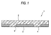
- Fig. 1 shows a sectional view of a friction material according to the present invention;
- Fig. 2 shows a process of producing a preform of the friction material according to the present invention in order of stages;
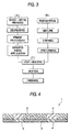
- Fig. 3 shows a flow chart of the process of producing the friction material according to the present invention; and
- Fig. 4 shows a sectional view of a conventional friction material.
-
- According to the present invention, a friction material contains a fibrous reinforcement, a binder resin, and a friction modifier. The binder content and fibrous reinforcement content of the friction material on the friction surface side to perform its function by friction are set to be smaller (in a range of from 5 % by weight to 20 % by weight) and larger (in a range of from 5 % by weight to 50 % by weight) respectively in order to make friction performance good. On the other hand, the binder content and fibrous reinforcement content of the friction material on the back plate side having no direct relation with friction are set to be larger (in a range of from 10 % by weight to 50 % by weight) and smaller (in a range of from 0 % by weight to 20 % by weight) respectively than those on the friction surface side in order to make strength, or the like, large.
- By this measure, strength, or the like, can be made large on the back plate side of the friction material, so that mechanical strength of the friction material as a whole can be improved.
- Fig. 3 shows a process which is performed conventionally, for example, for producing a disc brake pad. This producing process comprises: (A) a line for processing a back plate; (B) a line for preforming a friction material; and (C) a line for processing a product from the processed members obtained in (A) and (B) respectively.
- This process is as follows. A back plate is molded to a predetermined shape by means of sheet metal pressing, subjected to degreasing and primer processing and coated with an adhesive agent. Fibrous reinforcement such as heat-resistant organic or inorganic fiber, metal fiber, or the like, is mixed with powder material such as an inorganic or organic filler, a friction modifier, a thermosetting resin binder, or the like. Then, the mixture is stirred to thereby prepare sufficiently homogeneous raw material. The raw material is preformed at a room temperature under a predetermined pressure to prepare a preform. The back plate and the preform are subjected to heat molding at a predetermined temperature under a predetermined pressure so that the back plate and the preform are integrally fixed with each other, and then subjected to heating (after curing). The cured matter is finally subjected to the finishing step.
- Fig. 2 is for explaining the process of producing a friction material according to the present invention in order of stages. Fig. 2 is equivalent to the portion of the preforming step in the producing process shown in Fig. 3. This step is separated into stages (a) to (d). The
reference numeral 10 designates a mold combination as a whole; and 11, 12 and 13, molds respectively. Themolds 13 are used for formingcavity portions 14 necessary for forming protrusions. - The stage (a) shows the condition in which a resin-
rich mixture material 15 having a large amount of resin is packed in the mold combination. This mixture material may be packed as powder in the mold combination. However, because it is difficult to pack the mixture material with a uniform thickness, it may be rather convenient in terms of handling that the mixture material is slightly compressed in the form of a sheet so as to be carried easily. Further, the material portions above themolds 13 may be preferably provided asprotrusive portions 16 having an amount which can compensate the depression of a resin-richmixture material layer 17 to thereby prevent the upper surface of the resin-richmixture material layer 17 from depressing. - The stage (b) shows the condition in which the mixture material is preformed by an upper mold after the stage (a). The resin-rich
mixture material layer 17 thus molded hasprotrusions 18. Further, in the resin-richmixture material layer 17,cavity portions 19 are formed above theprotrusions 18 respectively. Thecavity portions 19 are provided for reinforcing the connection between the resin-richmixture material layer 17 and a conventional mixture material layer formed on the resin-richmixture material layer 17. Accordingly, in the stage (a), a mold having protrusive portions for forming thecavity portions 19 is used as the upper mold. - The stage (c) shows the condition in which a
conventional mixture material 20 is packed on the resin-richmixture material layer 17 obtained in the aforementioned stage (b). A composition good in friction performance is selected as the composition of theconventional mixture material 20 so that pores can be formed. - The stage (d) shows the condition in which the
conventional mixture material 20 packed in the aforementioned stage (c) is pressed so as to be preformed. The pressing operation is carried out by repeating pressing three times. Pressing is repeated three times for the purpose of making the density of the friction material uniform. The number of pressing is not limited to three times. - The preform obtained in the preforming step shown in the stages (a) to (d) is then heat-molded so that a friction material according to the present invention can be obtained.
- The friction material obtained according to the present invention is not different from any conventional product in terms of external appearance. With respect to the inner structure of the friction material according to the present invention, as shown in the vertical sectional view of Fig. 1, the density of the
protrusions 4 and portions above theprotrusions 4 is little different from that of other portions. That is, the density of theprotrusions 4 and portions above theprotrusions 4 is substantially equal to other portions in the friction material. - Examples of the aforementioned heat-resistant organic fiber include aromatic polyamide fibers, and flame-resistant acrylic fibers. Examples of the inorganic fiber include ceramic fibers such as potassium titanate fiber, alumina fiber, etc., glass fibers, carbon fibers, rock wool fibers, and so on. Examples of the metal fiber include copper fibers, and steel fibers.
- Examples of the inorganic filler include particles of metals such as copper, aluminum, zinc, etc., particles of flake-like inorganic substances such as vermiculite, mica, etc., and particles of barium sulfate, calcium carbonate, or the like. Examples of the organic filler include synthetic rubber, cashew resin, and so on.
- Examples of the thermosetting resin binder include phenol resin (inclusive of straight phenol resin, and various kinds of phenol resins modified by rubber, or the like), melamine resin, epoxy resin, cyanic acid ester resin, and so on.
- Examples of the friction modifier include metal oxides such as alumina, magnesia, zirconia, chrome oxide, quartz, etc., and so on. Examples of the solid lubricant include graphite, molybdenum disulfide, and so on.
- The present invention will be described below specifically but the present invention is not limited thereto.
- (1) First, a mixture material containing 30 % by weight of resin larger than the resin content of the conventional mixture material, and a smaller amount of fiber than the fiber content of the conventional mixture material and containing no abrasive and no lubricant as shown in Table 1 was put into a mold combination for preforming a friction material.
- (2) Then, the mixture material was pressed temporarily in order to make the protrusions dense.
- (3) Then, an operation of pressing the mixture material as a whole vertically and stopping the pressing was repeated three times thus to obtain a preformed friction material. In this occasion, the operation of pressing and stopping the pressing was repeated three times for the purpose of making the density of the friction material uniform with respect to the upper and lower surfaces of the friction material.
- (5) The preformed friction material was subjected to a heat-molding step in the same manner as in the conventional process. Thereafter, a finished product of the friction material was obtained via the steps of heating, polishing, etc.
-
- Incidentally, materials used in Table 1 were as follows. Phenol resin was used as the binder. Barium sulfate was used as the filler. Aramid fiber was used as the fibrous reinforcement. Ceramic particles were used as the abrasive contained in the friction modifier. Graphite was used as the lubricant contained in the friction modifier. Further, other components were used.
- On the other hand, in the aforementioned paragraph (5), the preform was pressed and heated so as to be heat-molded in the condition in which the preform was put on a coating surface of a back plate which was formed by means of sheet plate pressing, subjected to degreasing and primer processing and coated with an adhesive agent. The heat-molded matter was fed to the finishing step.
Conventional Mixture and Resin-Rich Mixture (% by weight) Resin-rich mixture (back plate side) Conventional mixture (friction surface side) Kind Component Binder Phenol resin 30 7 Filler Barium sulfate 55 42 Fibrous Reinforcement Aramid fiber, Titanate potassium fiber 5 21 Abrasive Various kinds of ceramic particles 0 14 Lubricant Graphite, etc. 0 4 Friction modifier Rubber particles 10 12 - The friction performance of the friction material obtained according to the present invention in the aforementioned manner was as high as that of the conventional friction material. Furthermore, the protrusions of the friction material according to the present invention was hardened to have a hardness of from HRS 74 to HRS 82 whereas the hardness of the protrusions of the conventional friction material was from HRS 60 to HRS 76. Furthermore, the bending strength of the friction material according to the present invention was improved to be in a range of from 15 to 25 kgf whereas the bending strength of the conventional friction material was from 6 to 15 kgf. In addition, the density distribution of the friction material according to the present invention was uniform as a whole.
- In the friction material according to the present invention, from the structure thereof, the friction performance on the friction surface side is good and the amount of resin and the amount of fibrous material in the binder are large and small respectively on the back plate side. Accordingly, the strength of the friction material is high on the back plate side. Accordingly, a friction material good in friction performance and high in strength as a whole is obtained.
- Although the invention has been described in its preferred formed with a certain degree of particularity, it is understood that the present disclosure of the preferred form can be changed in the details of construction and in the combination and arrangement of parts without departing from the spirit and the scope of the invention as hereinafter claimed.
Claims (6)
- A friction material to be bonded on a back plate, comprising:a fibrous reinforcement;a binder; anda friction modifier,
wherein a content of the binder on a side of the back plate is made to be larger than the content of the binder on a friction surface side of the friction material, and content of the fibrous reinforcement on the side of the back plate is made to be smaller than the content of the fibrous reinforcement on the friction surface side of the friction material. - A friction material according to claim 1, wherein (i) the content of the binder is in a range of 5 % by weight to 20 % by weight and the content of the fibrous reinforcement is in a range of 5 % by weight to 50 % by weight on the friction surface side, and (ii) the content of the binder is in the range of 10 % by weight to 50 % by weight and the content of the fibrous reinforcement is in a range of 0 % by weight to 20 % by weight on the side of the back plate.
- A friction material according to claim 1, wherein said friction material has at least one protrusion to be fitted into a hole of the back plate, and a density of the protrusions is substantially equal to a density of remaining portions of the friction material.
- A friction pad comprising:a friction material; anda back plate on which said friction material is bonded,
wherein said friction material contains:a fibrous reinforcement;a binder; anda friction modifier,
wherein a content of the binder on a side of the back plate is made to be larger than the content of the binder on a friction surface side of the friction material, and content of the fibrous reinforcement on the sided of the back plate is made to be smaller than the content of the fibrous reinforcement on the friction surface side of the friction material. - A friction pad according to claim 4, wherein (i) the content of the binder is in a range of 5 % by weight to 20 % by weight and the content of the fibrous reinforcement is in a range of 5 % by weight to 50 % by weight on the friction surface side, and (ii) the content of the binder is in the range of 10 % by weight to 50 % by weight and the content of the fibrous reinforcement is in a range of 0 % by weight to 20 % by weight on the side of the back plate.
- A friction pad according to claim 4, wherein said friction material has at least one protrusion to be fitted into a hole of the back plate, and a density of the protrusions is substantially equal to a density of remaining portions of the friction material.
Applications Claiming Priority (2)
| Application Number | Priority Date | Filing Date | Title |
|---|---|---|---|
| JP6551298 | 1998-03-16 | ||
| JP6551298 | 1998-03-16 |
Publications (2)
| Publication Number | Publication Date |
|---|---|
| EP0943832A2 true EP0943832A2 (en) | 1999-09-22 |
| EP0943832A3 EP0943832A3 (en) | 2001-01-31 |
Family
ID=13289185
Family Applications (1)
| Application Number | Title | Priority Date | Filing Date |
|---|---|---|---|
| EP99105269A Withdrawn EP0943832A3 (en) | 1998-03-16 | 1999-03-15 | Friction material |
Country Status (2)
| Country | Link |
|---|---|
| US (1) | US6260674B1 (en) |
| EP (1) | EP0943832A3 (en) |
Cited By (2)
| Publication number | Priority date | Publication date | Assignee | Title |
|---|---|---|---|---|
| US6811820B2 (en) | 1999-12-13 | 2004-11-02 | Miba Frictec Gmbh | Friction lining for wet running |
| WO2015173768A1 (en) * | 2014-05-16 | 2015-11-19 | Freni Brembo S.P.A. | Friction assembly, brake calliper and manufacturing method |
Families Citing this family (12)
| Publication number | Priority date | Publication date | Assignee | Title |
|---|---|---|---|---|
| JP2000290636A (en) * | 1999-04-06 | 2000-10-17 | Akebono Brake Ind Co Ltd | Friction material |
| JP2001165210A (en) * | 1999-12-14 | 2001-06-19 | Nisshinbo Ind Inc | Disk brake, disk brake pad, and back plate for disk brake pad |
| JP2002020730A (en) * | 2000-07-12 | 2002-01-23 | Akebono Brake Ind Co Ltd | Non-asbestos friction material |
| JP2002362377A (en) * | 2001-06-01 | 2002-12-18 | Nsk Ltd | Steering column holding device for vehicle |
| US7047836B2 (en) * | 2002-02-01 | 2006-05-23 | Trw Inc. | Surface treatment for a locking mechanism |
| US20040147192A1 (en) * | 2003-01-24 | 2004-07-29 | Ballard Material Products Inc. | Carbon fiber friction material |
| DE102006026802B3 (en) * | 2006-06-07 | 2007-09-27 | Tmd Friction Services Gmbh | Brake lining, especially for vehicle disk brakes, is produced by compressing friction material with a grid in a mold |
| US8689671B2 (en) | 2006-09-29 | 2014-04-08 | Federal-Mogul World Wide, Inc. | Lightweight armor and methods of making |
| ITTO20070678A1 (en) * | 2007-09-26 | 2009-03-27 | Fq Innovation Technology S R L | BRAKING GROUP FOR MOTOR VEHICLES, MOTORCYCLES AND SIMILARS |
| JP5921567B2 (en) * | 2010-12-13 | 2016-05-24 | シェフラー テクノロジーズ アー・ゲー ウント コー. カー・ゲーSchaeffler Technologies AG & Co. KG | Manufacturing method of friction body |
| US20130240304A1 (en) * | 2012-03-19 | 2013-09-19 | United Technologies Corporation | Low conductivity brake pad |
| US9938034B2 (en) * | 2014-12-19 | 2018-04-10 | Coopervision International Holding Company, Lp | Method and apparatus relating to manufacture of molds for forming contact lenses |
Citations (1)
| Publication number | Priority date | Publication date | Assignee | Title |
|---|---|---|---|---|
| JPH1065512A (en) | 1996-08-20 | 1998-03-06 | Nippon Telegr & Teleph Corp <Ntt> | Power feeding constitution for logic circuit |
Family Cites Families (9)
| Publication number | Priority date | Publication date | Assignee | Title |
|---|---|---|---|---|
| FR1392681A (en) | 1964-02-07 | 1965-03-19 | Ferodo Sa | Improvements made to friction pads |
| DE69512957T3 (en) | 1994-04-26 | 2003-09-11 | Sumitomo Electric Industries, Ltd. | Process for the manufacture of disc brake pads |
| US5515950A (en) * | 1994-06-08 | 1996-05-14 | Pneumo Abex Corporation | Disc brake friction pad assembly |
| US5413194A (en) * | 1994-07-25 | 1995-05-09 | Pneumo Abex Corporation | Brake friction pad assembly |
| JPH0989016A (en) * | 1995-09-21 | 1997-03-31 | Sumitomo Electric Ind Ltd | Disk brake pad |
| CA2249621A1 (en) * | 1996-04-08 | 1997-10-16 | Karl T. Mckeague | Patterned surface friction materials, clutch plate members and methods of making and using same |
| DE19652778A1 (en) * | 1996-12-19 | 1998-06-25 | Textar Gmbh | Brake shoe |
| US5775465A (en) * | 1997-04-18 | 1998-07-07 | Vossler; Darby J. | Ladder support |
| US5984055A (en) * | 1997-11-21 | 1999-11-16 | Northrop Grumman Corporation | Integrated fiber reinforced ceramic matrix composite brake pad and back plate |
-
1999
- 1999-03-15 US US09/267,652 patent/US6260674B1/en not_active Expired - Fee Related
- 1999-03-15 EP EP99105269A patent/EP0943832A3/en not_active Withdrawn
Patent Citations (1)
| Publication number | Priority date | Publication date | Assignee | Title |
|---|---|---|---|---|
| JPH1065512A (en) | 1996-08-20 | 1998-03-06 | Nippon Telegr & Teleph Corp <Ntt> | Power feeding constitution for logic circuit |
Cited By (3)
| Publication number | Priority date | Publication date | Assignee | Title |
|---|---|---|---|---|
| US6811820B2 (en) | 1999-12-13 | 2004-11-02 | Miba Frictec Gmbh | Friction lining for wet running |
| WO2015173768A1 (en) * | 2014-05-16 | 2015-11-19 | Freni Brembo S.P.A. | Friction assembly, brake calliper and manufacturing method |
| US10119583B2 (en) | 2014-05-16 | 2018-11-06 | Freni Brembo S.P.A. | Friction assembly, brake calliper and manufacturing method |
Also Published As
| Publication number | Publication date |
|---|---|
| US6260674B1 (en) | 2001-07-17 |
| EP0943832A3 (en) | 2001-01-31 |
Similar Documents
| Publication | Publication Date | Title |
|---|---|---|
| US6260674B1 (en) | Friction material | |
| JP5183900B2 (en) | Non-asbestos friction member | |
| KR20120135087A (en) | Brake pad backing plate and brake pad usung the same | |
| KR101098482B1 (en) | Friction material | |
| US5712029A (en) | Friction material | |
| JP2013057337A (en) | Brake pad, and method of manufacturing the same | |
| US5576369A (en) | Friction material | |
| JPH11322960A (en) | Friction material | |
| US6080230A (en) | Friction material composition | |
| JP5183902B2 (en) | Non-asbestos friction member | |
| US20220373053A1 (en) | Friction material | |
| JP2991970B2 (en) | Friction material | |
| JP3782243B2 (en) | Friction material for brake | |
| US6632857B1 (en) | Friction material | |
| KR20110118592A (en) | Disc brake pad | |
| JP2002088345A (en) | Friction material for brake | |
| JP2006275198A (en) | Disc pad | |
| JP3228096B2 (en) | Manufacturing method of friction material | |
| JP3792839B2 (en) | Granulated product and friction material manufacturing method | |
| CN117836535A (en) | Underlayer material and friction member | |
| JPS5891935A (en) | Manufacture of brake plastic material | |
| JP2000219750A (en) | Friction material for brake | |
| JP2003074610A (en) | Mold for thermoforming friction material | |
| JP2000002276A (en) | Friction material | |
| JP2008144773A (en) | Friction material and its manufacturing method |
Legal Events
| Date | Code | Title | Description |
|---|---|---|---|
| PUAI | Public reference made under article 153(3) epc to a published international application that has entered the european phase |
Free format text: ORIGINAL CODE: 0009012 |
|
| AK | Designated contracting states |
Kind code of ref document: A2 Designated state(s): AT BE CH CY DE DK ES FI FR GB GR IE IT LI LU MC NL PT SE |
|
| AX | Request for extension of the european patent |
Free format text: AL;LT;LV;MK;RO;SI |
|
| PUAL | Search report despatched |
Free format text: ORIGINAL CODE: 0009013 |
|
| AK | Designated contracting states |
Kind code of ref document: A3 Designated state(s): AT BE CH CY DE DK ES FI FR GB GR IE IT LI LU MC NL PT SE |
|
| AX | Request for extension of the european patent |
Free format text: AL;LT;LV;MK;RO;SI |
|
| AKX | Designation fees paid | ||
| STAA | Information on the status of an ep patent application or granted ep patent |
Free format text: STATUS: THE APPLICATION IS DEEMED TO BE WITHDRAWN |
|
| 18D | Application deemed to be withdrawn |
Effective date: 20010801 |
|
| REG | Reference to a national code |
Ref country code: DE Ref legal event code: 8566 |