EP0943796A2 - Liquid filter for filtering fuel - Google Patents
Liquid filter for filtering fuel Download PDFInfo
- Publication number
- EP0943796A2 EP0943796A2 EP98119364A EP98119364A EP0943796A2 EP 0943796 A2 EP0943796 A2 EP 0943796A2 EP 98119364 A EP98119364 A EP 98119364A EP 98119364 A EP98119364 A EP 98119364A EP 0943796 A2 EP0943796 A2 EP 0943796A2
- Authority
- EP
- European Patent Office
- Prior art keywords
- liquid filter
- filter according
- channel
- connection
- end cap
- Prior art date
- Legal status (The legal status is an assumption and is not a legal conclusion. Google has not performed a legal analysis and makes no representation as to the accuracy of the status listed.)
- Granted
Links
- 239000007788 liquid Substances 0.000 title claims abstract description 49
- 239000000446 fuel Substances 0.000 title claims abstract description 12
- 238000001914 filtration Methods 0.000 title 1
- XLYOFNOQVPJJNP-UHFFFAOYSA-N water Substances O XLYOFNOQVPJJNP-UHFFFAOYSA-N 0.000 claims abstract description 24
- 238000003860 storage Methods 0.000 claims abstract description 16
- 238000010438 heat treatment Methods 0.000 claims description 11
- 230000008719 thickening Effects 0.000 claims description 11
- 238000007789 sealing Methods 0.000 claims description 7
- 238000007373 indentation Methods 0.000 claims description 6
- 238000004140 cleaning Methods 0.000 claims description 5
- 238000005485 electric heating Methods 0.000 claims description 2
- 230000007704 transition Effects 0.000 claims 1
- NJPPVKZQTLUDBO-UHFFFAOYSA-N novaluron Chemical compound C1=C(Cl)C(OC(F)(F)C(OC(F)(F)F)F)=CC=C1NC(=O)NC(=O)C1=C(F)C=CC=C1F NJPPVKZQTLUDBO-UHFFFAOYSA-N 0.000 abstract 2
- 239000012530 fluid Substances 0.000 abstract 1
- 239000002283 diesel fuel Substances 0.000 description 5
- 238000002347 injection Methods 0.000 description 4
- 239000007924 injection Substances 0.000 description 4
- 238000010276 construction Methods 0.000 description 3
- 230000008901 benefit Effects 0.000 description 2
- 238000009434 installation Methods 0.000 description 2
- 238000000926 separation method Methods 0.000 description 2
- 230000004323 axial length Effects 0.000 description 1
- 230000008859 change Effects 0.000 description 1
- 230000001419 dependent effect Effects 0.000 description 1
- 238000011161 development Methods 0.000 description 1
- 230000018109 developmental process Effects 0.000 description 1
- 230000002349 favourable effect Effects 0.000 description 1
- 238000004519 manufacturing process Methods 0.000 description 1
- 239000002184 metal Substances 0.000 description 1
- 238000011144 upstream manufacturing Methods 0.000 description 1
- 238000003466 welding Methods 0.000 description 1
Images


Classifications
-
- B—PERFORMING OPERATIONS; TRANSPORTING
- B01—PHYSICAL OR CHEMICAL PROCESSES OR APPARATUS IN GENERAL
- B01D—SEPARATION
- B01D29/00—Filters with filtering elements stationary during filtration, e.g. pressure or suction filters, not covered by groups B01D24/00 - B01D27/00; Filtering elements therefor
- B01D29/96—Filters with filtering elements stationary during filtration, e.g. pressure or suction filters, not covered by groups B01D24/00 - B01D27/00; Filtering elements therefor in which the filtering elements are moved between filtering operations; Particular measures for removing or replacing the filtering elements; Transport systems for filters
-
- B—PERFORMING OPERATIONS; TRANSPORTING
- B01—PHYSICAL OR CHEMICAL PROCESSES OR APPARATUS IN GENERAL
- B01D—SEPARATION
- B01D29/00—Filters with filtering elements stationary during filtration, e.g. pressure or suction filters, not covered by groups B01D24/00 - B01D27/00; Filtering elements therefor
- B01D29/11—Filters with filtering elements stationary during filtration, e.g. pressure or suction filters, not covered by groups B01D24/00 - B01D27/00; Filtering elements therefor with bag, cage, hose, tube, sleeve or like filtering elements
- B01D29/13—Supported filter elements
- B01D29/15—Supported filter elements arranged for inward flow filtration
- B01D29/21—Supported filter elements arranged for inward flow filtration with corrugated, folded or wound sheets
-
- B—PERFORMING OPERATIONS; TRANSPORTING
- B01—PHYSICAL OR CHEMICAL PROCESSES OR APPARATUS IN GENERAL
- B01D—SEPARATION
- B01D35/00—Filtering devices having features not specifically covered by groups B01D24/00 - B01D33/00, or for applications not specifically covered by groups B01D24/00 - B01D33/00; Auxiliary devices for filtration; Filter housing constructions
- B01D35/14—Safety devices specially adapted for filtration; Devices for indicating clogging
- B01D35/147—Bypass or safety valves
-
- B—PERFORMING OPERATIONS; TRANSPORTING
- B01—PHYSICAL OR CHEMICAL PROCESSES OR APPARATUS IN GENERAL
- B01D—SEPARATION
- B01D35/00—Filtering devices having features not specifically covered by groups B01D24/00 - B01D33/00, or for applications not specifically covered by groups B01D24/00 - B01D33/00; Auxiliary devices for filtration; Filter housing constructions
- B01D35/18—Heating or cooling the filters
-
- B—PERFORMING OPERATIONS; TRANSPORTING
- B01—PHYSICAL OR CHEMICAL PROCESSES OR APPARATUS IN GENERAL
- B01D—SEPARATION
- B01D36/00—Filter circuits or combinations of filters with other separating devices
- B01D36/003—Filters in combination with devices for the removal of liquids
-
- F—MECHANICAL ENGINEERING; LIGHTING; HEATING; WEAPONS; BLASTING
- F02—COMBUSTION ENGINES; HOT-GAS OR COMBUSTION-PRODUCT ENGINE PLANTS
- F02M—SUPPLYING COMBUSTION ENGINES IN GENERAL WITH COMBUSTIBLE MIXTURES OR CONSTITUENTS THEREOF
- F02M37/00—Apparatus or systems for feeding liquid fuel from storage containers to carburettors or fuel-injection apparatus; Arrangements for purifying liquid fuel specially adapted for, or arranged on, internal-combustion engines
- F02M37/22—Arrangements for purifying liquid fuel specially adapted for, or arranged on, internal-combustion engines, e.g. arrangements in the feeding system
- F02M37/24—Arrangements for purifying liquid fuel specially adapted for, or arranged on, internal-combustion engines, e.g. arrangements in the feeding system characterised by water separating means
-
- F—MECHANICAL ENGINEERING; LIGHTING; HEATING; WEAPONS; BLASTING
- F02—COMBUSTION ENGINES; HOT-GAS OR COMBUSTION-PRODUCT ENGINE PLANTS
- F02M—SUPPLYING COMBUSTION ENGINES IN GENERAL WITH COMBUSTIBLE MIXTURES OR CONSTITUENTS THEREOF
- F02M37/00—Apparatus or systems for feeding liquid fuel from storage containers to carburettors or fuel-injection apparatus; Arrangements for purifying liquid fuel specially adapted for, or arranged on, internal-combustion engines
- F02M37/22—Arrangements for purifying liquid fuel specially adapted for, or arranged on, internal-combustion engines, e.g. arrangements in the feeding system
- F02M37/30—Arrangements for purifying liquid fuel specially adapted for, or arranged on, internal-combustion engines, e.g. arrangements in the feeding system characterised by heating means
-
- F—MECHANICAL ENGINEERING; LIGHTING; HEATING; WEAPONS; BLASTING
- F02—COMBUSTION ENGINES; HOT-GAS OR COMBUSTION-PRODUCT ENGINE PLANTS
- F02M—SUPPLYING COMBUSTION ENGINES IN GENERAL WITH COMBUSTIBLE MIXTURES OR CONSTITUENTS THEREOF
- F02M37/00—Apparatus or systems for feeding liquid fuel from storage containers to carburettors or fuel-injection apparatus; Arrangements for purifying liquid fuel specially adapted for, or arranged on, internal-combustion engines
- F02M37/22—Arrangements for purifying liquid fuel specially adapted for, or arranged on, internal-combustion engines, e.g. arrangements in the feeding system
- F02M37/32—Arrangements for purifying liquid fuel specially adapted for, or arranged on, internal-combustion engines, e.g. arrangements in the feeding system characterised by filters or filter arrangements
- F02M37/42—Installation or removal of filters
-
- F—MECHANICAL ENGINEERING; LIGHTING; HEATING; WEAPONS; BLASTING
- F02—COMBUSTION ENGINES; HOT-GAS OR COMBUSTION-PRODUCT ENGINE PLANTS
- F02M—SUPPLYING COMBUSTION ENGINES IN GENERAL WITH COMBUSTIBLE MIXTURES OR CONSTITUENTS THEREOF
- F02M37/00—Apparatus or systems for feeding liquid fuel from storage containers to carburettors or fuel-injection apparatus; Arrangements for purifying liquid fuel specially adapted for, or arranged on, internal-combustion engines
- F02M37/22—Arrangements for purifying liquid fuel specially adapted for, or arranged on, internal-combustion engines, e.g. arrangements in the feeding system
- F02M37/32—Arrangements for purifying liquid fuel specially adapted for, or arranged on, internal-combustion engines, e.g. arrangements in the feeding system characterised by filters or filter arrangements
- F02M37/48—Filters structurally associated with fuel valves
-
- B—PERFORMING OPERATIONS; TRANSPORTING
- B01—PHYSICAL OR CHEMICAL PROCESSES OR APPARATUS IN GENERAL
- B01D—SEPARATION
- B01D2201/00—Details relating to filtering apparatus
- B01D2201/30—Filter housing constructions
- B01D2201/301—Details of removable closures, lids, caps, filter heads
- B01D2201/302—Details of removable closures, lids, caps, filter heads having inlet or outlet ports
-
- B—PERFORMING OPERATIONS; TRANSPORTING
- B01—PHYSICAL OR CHEMICAL PROCESSES OR APPARATUS IN GENERAL
- B01D—SEPARATION
- B01D2201/00—Details relating to filtering apparatus
- B01D2201/30—Filter housing constructions
- B01D2201/301—Details of removable closures, lids, caps, filter heads
- B01D2201/304—Seals or gaskets
-
- B—PERFORMING OPERATIONS; TRANSPORTING
- B01—PHYSICAL OR CHEMICAL PROCESSES OR APPARATUS IN GENERAL
- B01D—SEPARATION
- B01D2201/00—Details relating to filtering apparatus
- B01D2201/46—Several filtrate discharge conduits each connected to one filter element or group of filter elements
Landscapes
- Engineering & Computer Science (AREA)
- Chemical & Material Sciences (AREA)
- Combustion & Propulsion (AREA)
- Mechanical Engineering (AREA)
- General Engineering & Computer Science (AREA)
- Chemical Kinetics & Catalysis (AREA)
- Filtration Of Liquid (AREA)
Abstract
Description
Die Erfindung geht aus von einem Flüssigkeitsfilter zum Reinigen von Kraftstoff nach der im Oberbegriff des Anspruchs 1 näher angegebenen Gattung.The invention relates to a liquid filter Clean fuel according to the preamble of Claim 1 specified genus.
Es ist schon ein solches Flüssigkeitsfilter zum Reinigen von Kraftstoff aus der US-PS 5 433 241 bekannt, bei dem das Gehäuse in Vollkunststoffausführung ausgeführt ist. Dabei hat das Gehäuse ein becherförmiges Unterteil mit einem Zulaufanschluß und einem Rücklaufanschluß eines Druckreglers; ein deckelförmiges Oberteil des Gehäuses hat einen Schlauchstutzen als Ablaufanschluß von der Reinseite. Ein im Unterteil eingebautes Zusatzgehäuse bildet mit dem Unterteil zusammen einen Raum zur Aufnahme des Druckreglers, der den Druck auf der Reinseite eines radial durchströmten Filtereinsatzes begrenzt. Das Zusatzgehäuse bildet mit dem Oberteil einen Innenraum, der den Filtereinsatz aufnimmt. Zur lösbaren Befestigung von Unterteil und Oberteil dient eine in das Unterteil radial eingeschobene, U-förmige Spannfeder. Es ist nun von Nachteil, daß sich dieses Flüssigkeitsfilter mit seinem Kunststoffgehäuse nur zum Reinigen von Benzin eignet, da kein Wasserspeicherraum vorgesehen ist. Auch fehlt eine Heizeinrichtung auf der Schmutzseite. Ferner baut das Flüssigkeitsfilter insofern aufwendig, als sein Gehäuse aus mindestens drei ineinandergesteckten Kunststoffteilen besteht, so daß der Filtereinsatz von einer Doppelwand umgeben ist. Auch kann bei dieser Bauweise das Oberteil mit dem Unterteil nicht durch eine Schnellverschraubung lösbar verbunden werden.It is already such a liquid filter for cleaning Fuel known from US Pat. No. 5,433,241, in which the Housing is made of fully plastic. Here the housing has a cup-shaped lower part with a Inlet connection and a return connection of a Pressure regulator; has a lid-shaped upper part of the housing a hose connector as a drain connection from the clean side. An additional housing installed in the lower part forms with the Together lower part of a space for receiving the pressure regulator, which flowed through the pressure on the clean side of a radial Filter insert limited. The additional housing forms with the Upper part an interior that receives the filter insert. For detachable fastening of the lower part and upper part one in the lower part radially inserted, U-shaped Tension spring. It is now a disadvantage that this Liquid filter with its plastic housing only for Cleaning petrol is suitable because there is no water storage space is provided. A heater is also missing on the Dirt side. Furthermore, the liquid filter builds elaborate than its housing of at least three nested plastic parts, so that the Filter insert is surrounded by a double wall. Can too in this construction, the upper part with the lower part is not can be detachably connected by a quick screw connection.
Ferner ist auch ein Flüssigkeitsfilter für Dieselkraftstoff aus der EP 0 702 144 B1 bekannt, das im Gehäuse einen unterhalb des austauschbaren Filtereinsatzes liegenden Wasserspeicherraum aufweist, während im Filterkopf neben den fluidischen und elektrischen Anschlüssen eine elektrische Heizeinrichtung angeordnet ist. Dieses Filter hat ein Gehäuse aus Metall sowie einen mehrteiligen Filterkopf in Modulbauweise, so daß sich diese Gehäusebauweise schlecht für eine Vollkunststoffausführung eignet. Weiterhin fehlt hier ein Überströmventil mit einem zugeordneten Tankanschluß.There is also a liquid filter for diesel fuel known from EP 0 702 144 B1, the one in the housing below the exchangeable filter insert Has water storage space, while in the filter head next to the fluidic and electrical connections an electrical Heating device is arranged. This filter has a Metal housing and a multi-part filter head in Modular construction, so that this housing construction is bad suitable for a fully plastic version. Still missing here an overflow valve with an associated one Tank connection.
Das erfindungsgemäße Flüssigkeitsfilter mit den kennzeichnenden Merkmalen des Hauptanspruchs hat demgegenüber den Vorteil, daß es ein einfach und kompakt bauendes Dieselfilter ermöglicht, in dessen Gehäuse in Vollkunststoffausführung ein Wasserspeicherraum auf der Reinseite und eine Heizeinrichtung im Zulauf integriert sind. Das Gehäuse laßt sich trotzdem im wesentlichen zweiteilig ausbilden und kommt ohne ein drittes Gehäuseteil aus, was platzsparend und vor allem kostengünstig ist; ein verschmutzter Filtereinsatz läßt sich dadurch leicht austauschen. The liquid filter according to the invention with the has characteristic features of the main claim in contrast the advantage that it is a simple and compact building diesel filter allows in its housing in All-plastic design a water storage room on the Clean side and a heating device integrated in the inlet are. The housing can still be essentially train in two parts and comes without a third housing part from what is space-saving and above all inexpensive; a dirty filter insert can be easily change.
Durch die in den Unteransprüchen aufgeführten Maßnahmen sind
vorteilhafte Weiterbildungen und Verbesserungen des im
Anspruch 1 angegebenen Flüssigkeitsfilters möglich.
Besonders vorteilhaft ist eine Ausbildung nach den
Ansprüchen 2 und 3, wodurch die elektrische Heizeinrichtung
besonders zweckmäßig im Gehäuse integriert werden kann.
Besonders vorteilhafte und kompakte Bauweisen ergeben sich
nach den Ansprüchen 4 bis 7, so daß in dem Unterteil mit
Hilfe einer am Filtereinsatz anliegenden Formdichtung neben
der Abdichtung von Schmutz- und Reinseite auch die
notwendigen Druckmittelverbindungen zur Heizeinrichtung
geschaffen werden, wobei die Heizeinrichtung unterhalb des
Wasserspeicherraums im Sockelabschnitt raumsparend
angeordnet werden kann. Dabei werden die Dichtfunktionen und
die Verbindungsfunktionen in besonders einfacher und
günstiger Weise hergestellt. Besonders zweckmäßige
Ausgestaltungen der Anschlüsse am Gehäuse lassen sich
erzielen, wenn das Flüssigkeitsfilter gemäß den Ansprüchen 9
und 10 ausgeführt wird. Ferner ist es vorteilhaft, wenn
gemäß Anspruch 11 die beiden Gehäuseteile mittels eines
Schnell-Schraubverschlusses lösbar miteinander verbunden
werden. Die Innenabdichtung zwischen deckelartigem Oberteil
und Filtereinsatz kann dabei gemäß Anspruch 12 günstig
ausgebildet werden. Ferner ist es von Vorteil, das
Flüssigkeitsfilter gemäß Anspruch 13 auszuführen, wodurch
ein Überströmventil am Deckel angebaut werden kann und die
Abflüsse zur Einspritzpumpe bzw. zum Tank am deckelförmigen
Oberteil auf gleicher Höhe angeordnet werden können. Günstig
ist ferner, wenn das Überströmventil gemäß Anspruch 14 als
austauschbarer Ventilmodul am Oberteil angeordnet wird. Für
eine einfache Montage und sichere Betriebsweise ist es
vorteilhaft, wenn gemäß Anspruch 15 eine Verdrehsicherung
für den Filtereinsatz im Gehäuse vorgesehen wird. Ferner
wird durch eine Ausbildung nach den Ansprüchen 16, 17 eine
kompakte, kostengünstige und relativ einfache Bauweise
begünstigt. Weitere vorteilhafte Ausgestaltungen ergeben
sich aus den übrigen Ansprüchen, der Beschreibung und der
Zeichnung.By the measures listed in the subclaims
advantageous further developments and improvements of the
Claim 1 specified liquid filter possible.
Training according to the
Claims 2 and 3, whereby the electric heater
can be integrated into the housing particularly expediently.
Particularly advantageous and compact designs result
according to claims 4 to 7, so that in the lower part with
With the help of a molded seal next to the filter insert
the sealing of dirt and clean side also the
necessary pressure medium connections to the heating device
be created, the heating device below the
Water storage space in the base section to save space
can be arranged. The sealing functions and
the connection functions in particularly simple and
manufactured in a favorable manner. Particularly useful
The connections on the housing can be configured
achieve if the liquid filter according to
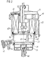
Ein Ausführungsbeispiel der Erfindung ist in der Zeichnung dargestellt und in der nachfolgenden Beschreibung näher erläutert. Es zeigen die Figur 1 einen Längsschnitt durch ein Flüssigkeitsfilter zum Reinigen von Dieselkraftstoff in vereinfachter Darstellung, wobei der Schnittverlauf teilweise nach I-I in Figur 3 dargestellt ist, Figur 2 einen Längsschnitt durch das Flüssigkeitsfilter nach II-II in Figur 1 in vereinfachter Darstellung, Figur 3 eine Draufsicht auf das Unterteil eines Gehäuses des Flüssigkeitsfilters nach Figur 1, Figur 4 eine Ansicht der Endkappe nach Pfeil IV in Figur 2 mit einer gegenüber Figur 1 leicht geänderten Halterung des Formdichtrings und Figur 5 einen Längsschnitt nach IV-IV in Figur 4.An embodiment of the invention is in the drawing shown and in the following description explained. 1 shows a longitudinal section through a liquid filter for cleaning diesel fuel in Simplified representation, with the course of the cut is partially shown according to I-I in Figure 3, Figure 2 one Longitudinal section through the liquid filter according to II-II in Figure 1 in a simplified representation, Figure 3 a Top view of the lower part of a housing of the Liquid filter according to Figure 1, Figure 4 is a view of End cap according to arrow IV in Figure 2 with an opposite figure 1 slightly modified holder of the molded sealing ring and Figure 5 a longitudinal section according to IV-IV in Figure 4.
Die Figur 1 zeigt einen Längsschnitt durch ein
Flüssigkeitsfilter 10 zum Reinigen von Dieselkraftstoff mit
einem zweiteiligen Gehäuse 11, das in
Vollkunststoffausführung ausgebildet ist. Das Gehäuse hat
ein im wesentlichen becherförmiges Unterteil 12 und ein
deckelförmiges Oberteil 13, die beide aus Kunststoff
bestehen. Unterteil und Oberteil sind durch einen Schnell-Schraubverschluß
14 lösbar miteinander verbunden, wozu ein
entsprechendes Steilgewinde vorgesehen ist und das Oberteil
13 das Unterteil 12 außen übergreift. In dem vom Unterteil
12 und Oberteil 13 eingeschlossenen Innenraum 15 ist ein
radial von innen nach außen durchströmter Filtereinsatz 16
angeordnet, der zwischen eine mit einem Zulaufanschluß 17
verbundene Schmutzseite 18 und einen mit einer Reinseite 19
verbundenen Ablaufanschluß 21 geschaltet ist.1 shows a longitudinal section through a
Wie die Figur 1 in Verbindung mit Figur 2 naher zeigt, geht
das becherförmige Unterteil 12 von einem kreiszylindrischen,
zum Oberteil 13 hin offenen Abschnitt 22 über eine
ringförmige Schulter 23 in einen Sockelabscbnitt 24 über,
dessen Außendurchmesser gegenüber dem Abschnitt 22
verringert ist. Die Schulter bildet dadurch eine dem
Innenraum 15 zugewandte, ringförmig verlaufende
Schulterfläche 25. In dem unterhalb der Schulter 23
liegenden Sockelabschnitt 24 ist zwischen dessen Boden 26
und dem Filtereinsatz 16 ein Wasserspeicherraum 27
ausgebildet, der mit der Reinseite 19 im Filtereinsatz 16
Verbindung hat.As FIG. 1 shows in connection with FIG. 2, goes
the cup-shaped
Wie Figur 1 ferner zeigt, ist an dem Sockelabschnitt 24 der
Zulaufanschluß 17 angeordnet, der in einer radial zur
Längsachse 28 des Flüssigkeitsfilters 10 verlaufenden Ebene
liegt und der zugleich schräg zur Mantelfläche des
Sockelabschnitts 24 verläuft, wie dies Figur 3 besonders
deutlich zeigt, die eine Draufsicht auf das Unterteil 12
darstellt. Der Zulaufanschluß 17 ist als
Schlauchanschlußstutzen ausgebildet und führt das ankommende
Druckmittel unmittelbar in einen Zuströmkanal 29. Um diesen
Zuströmkanal 29 im Sockelabschnitt 24 unterzubringen, ist im
Bereich dessen Außenumfangs eine hülsenförmige Verdickung 31
angeformt, wie dies Figur 3 besonders deutlich zeigt. Der
Zulaufanschluß 17 führt radial an diese hülsenförmige
Verdickung 31 heran. Der Zuströmkanal 29 ist wie eine
sacklochartige Ausnehmung ausgebildet, ist also in der
Schulterfläche 25 geschlossen, während er eine im Boden 26
liegende Öffnung 30 aufweist. Die Achse des Zuströmkanals 29
verläuft ebenfalls parallel zu der Längsachse 28 des
Flüssigkeitsfilters 10. As FIG. 1 also shows, the
Wie Figur 1 in Verbindung mit Figur 2 näher zeigen, ist im
Gehäuse 11 eine elektrische Heizeinrichtung 32 integriert,
indem sie in kompakter und raumsparender Bauweise unterhalb
des Sockelabschnitts 24 angeordnet ist. Das Gehäuse 11 weist
zu diesem Zweck ein im wesentlichen becherförmiges
Schalenteil 33 auf, das mit seinem freien Rand 34 dicht und
fest am Boden 26 des Sockelabschnitts 24 befestigt ist. Das
Schalenteil 33 besteht ebenfalls aus Kunststoff und wird
zweckmäßiger Weise mit dem Unterteil 12 verschweißt. Das
Schalenteil 33 nimmt in seinem Inneren an sich bekannte
elektrische Heizelemente 35 auf, die von dem zu reinigenden
Flüssigkeitsstrom umspült werden. Diese Heizelemente 35
liegen somit in einem Heizungsraum 36, der einerseits über
die Öffnung 31 des Zuströmkanals 29 mit dem Zulaufanschluß
17 Verbindung hat, während er andererseits über einen
Abströmkanal 37 mit der Schmutzseite 18 am Filtereinsatz 16
in Verbindung steht. Außen am Schalenteil 33 ist zentrisch
in der Längsachse 28 ein elektrischer Steckanschluß 40 für
eine elektrische Heizeinrichtung 32 angeordnet.As shown in FIG. 1 in connection with FIG. 2,
Wie aus Figur 1 in Verbindung mit Figur 3 näher zu erkennen
ist, verläuft im Sockelabschnitt 24 eine zweite
hülsenförmige Verdickung 38, in welcher der Abströmkanal 37
angeordnet ist. Wie dabei Figur 3 naher zeigt, liegt diese
zweite Verdickung 38 etwa um einen Drehwinkel von ca. 90°
zur ersten hülsenförmige Verdickung 31 versetzt und ist in
ihrer radialen Ausdehnung kleiner. Diese zweite Verdickung
38 liegt ebenfalls im Bereich des Außenumfangs des
Sockelabschnitts 24, so daß der in ihr angeordnete, gerade
verlaufende Abströmkanal 37 eine Kanalöffnung 39 bildet, die
unmittelbar neben der Schulter 23 liegt und dabei von einer
Ausbuchtung der Schulterfläche 25 umschlungen ist, wie dies
Figur 3 deutlich zeigt. As can be seen in more detail from FIG. 1 in connection with FIG
a second runs in the
Ferner ist in dem Sockelabschnitt 24 im Bereich des
Wasserspeicherraums 27 eine vom Boden 26 aus senkrecht nach
oben ragende, fingerartige Rippe 42 angeordnet, die als Teil
einer Verdrehsicherung 43 für den Filtereinsatz 16 dient. Im
Bereich zwischen den beiden Verdickungen 31 und 38 ist am
Boden 26 des Sockelabschnitts 24 ein Wasserablaß 44
angeordnet, der durch eine Verschlußschraube 45 absperrbar
ist. Durch diese Ausbildung kann das Unterteil 12 des
Gehäuses 11 als einstückiges Teil aus Kunststoff gespritzt
werden.Furthermore, in the
Bei dem im Innenraum 15 des Gehäuses 11 angeordneten
Filtereinsatz 16, handelt es sich um einen üblichen,
kreisringförmigen Sternfiltereinsatz, der an seiner unteren
Endkappe 46 und seiner oberen Endkappe 47 zur Trennung von
Schmutzseite 18 und Reinseite 19 abgedichtet wird. Zu diesem
Zweck ist an der ringförmigen, unteren Endkappe 46 eine
besondere Formdichtung 48 angeordnet, welche die Abdichtung
zwischen der Schulterfläche 25 im Gehäuse 11 und dem
Filtereinsatz 16 übernimmt.When arranged in the
Die Figur 4 zeigt nun eine Ansicht der unteren Endkappe 46
nach Pfeilrichtung IV in Figur 2, aus der der besondere
Verlauf der Formdichtung 48 erkennbar wird. Wie die Figur 4
in Verbindung mit Figur 5 näher zeigt, ist auf der
kreisringförmigen Endkappe 46 ein ringförmig verlaufendes
Halteblech 49 durch mehrere Schweißpunkte 51 befestigt, so
daß die Formdichtung 48 mit ihrem L-förmigen Querschnitt
eingehängt werden kann. Formdichtung 48 und Halteblech 49
sind so ausgeführt, daß die Formdichtung 48 im wesentlichen
entlang des äußeren Umfangs der Endkappe 46 verläuft, jedoch
in einem der ersten Verdickung 31 zugeordneten Bereich eine
erste Einbuchtung 52 und im Bereich der Kanalöffnung 39 eine
der zweiten Verdickung 38 zugeordnete, zweite Einbuchtung 53
aufweist. Bei der Montage des Filtereinsatzes 16 in dem
Unterteil 12 kommt dabei die Formdichtung 48 derart auf der
Schulterfläche 25 zu liegen, daß der Abströmkanal 37 über
seine Kanalöffnung 39 unmittelbar mit der Schmutzseite 18 am
Filtereinsatz 16 Verbindung hat. Die axiale Höhe der
Formdichtung 48 ist dabei so groß gewählt, daß zwischen der
Kanalöffnung 39 und der unteren Endkappe 46 ein ausreichend
hoher, radial sich erstreckender Durchflußquerschnitt
verbleibt, über den das zu reinigende Druckmittel nach außen
in den ringförmigen Raum zwischen den Filtereinsatz 16 und
dem Abschnitt 22 des Gehäuses 11 strömen kann.FIG. 4 now shows a view of the
In Figur 4 ist ferner besonders deutlich eine Nut 54 in der
unteren Endkappe 46 erkennbar, in welche die Rippe 42 zum
Erreichen einer Funktion der Verdrehsicherung 43 eingeführt
wird. Die axiale Länge dieser Rippe 42 ist dabei so groß
gewählt, daß sie in den Filtereinsatz 16 hineinragt. Über
eine zentrale Öffnung 55 in der unteren Endkappe 46 steht
die Reinseite 19 unmittelbar mit dem Wasserspeicherraum 27
in Verbindung.A
Am deckelförmigen Oberteil 13 ist zentral ein zylindrischer
Rohrstutzen 56 ausgebildet, der in den Filtereinsatz 16
hineinragt und an dessen Mantelfläche 57 eine ringförmige
Dichtmanschette 58 anliegt. Diese Dichtmanschette 58 sitzt
am inneren Rand der oberen Endkappe 47 und dichtet somit
zwischen Schmutzseite 18 und Reinseite 19 ab. An dem
Rohrstutzen 56 ist der Ablaufanschluß 21 angeordnet, der als
radial abstehender Schlauchanschlußstutzen ausgeführt ist
und der über einen Ablaufkanal 59 mit ringförmigen
Querschnitt mit der Reinseite 19 in Verbindung steht. Der
ringförmige Ablaufkanal 59 umgibt einen zentral liegenden,
zweiten Ablaufkanal 60, der in winkliger Form geführt ist
und zu einem zweiten Ablaufanschluß 61 führt. Der zweite
Ablaufanschluß 61 liegt gleichachsig zum ersten
Ablaufanschluß 21 und ist wie dieser als
Schlauchanschlußstutzen ausgeführt. Beide Anschlüsse 21, 61
liegen somit in einer radial zur Längsachse 28 des
Flüssigkeitsfilters verlaufenden Ebene. Der zweite
Ablaufkanal 60 weist am Ende des Rohrstutzens 56 eine in die
Reinseite 19 hineinragende, rohrförmige Verlängerung 62 auf,
an der ein Überströmventil 63 befestigt ist. Dieses
Überströmventil 63 ist als austauschbare Ventilpatrone mit
einem federbelasteten Kugelventil ausgeführt und ermöglicht
ein Abströmen von Druckmittel aus der Reinseite 19 zum
zweiten Ablaufanschluß 61, wenn der im Überströmventil 63
eingestellte Druck überschritten wird.At the lid-shaped
Um den Filtereinsatz 16 im Innenraum 15 in seiner Lage zu
halten, ist zwischen dem Oberteil 13 und der oberen Endkappe
47 eine Wellfeder 64 angeordnet, welche den Filtereinsatz 16
mit der Formdichtung 48 auf die Schulterfläche 25 drückt und
somit für eine sichere Abdichtung zwischen Schmutzseite und
Reinseite sorgt. Um den Flüssigkeitsfilter 10 an einem
anderen Maschinenteil befestigen zu können, ist am Unterteil
12 des Gehäuses 11 ein Flansch 65 angeformt, wie dies
besonders deutlich aus Figur 2 erkennbar ist.To position the
Die Wirkungsweise des Flüssigkeitsfilters 10 wird wie folgt
erläutert, wobei die grundsätzliche Funktion derartiger
Filter als bekannt vorausgesetzt wird.The operation of the
Der zu reinigende Dieselkraftstoff wird dem
Flüssigkeitsfilter 10 am Zulaufanschluß 17 zugeführt und
fließt über den Zuströmkanal 29 unmittelbar in den
Heizungsraum 36 der elektrischen Heizeinrichtung 32. Bei
Bedarf wird dort der Kraftstoff durch die elektrischen
Heizelemente 35 erwärmt und fließt dann vom Heizungsraum 36
weiter in den Abströmkanal 37. Über die Kanalöffnung 39 in
der Schulterfläche 25 und durch die von der Formdichtung 48
abgegrenzte Ausnehmung zwischen der unteren Endkappe 46
sowie der Schulterfläche 25 gelangt er auf die Schmutzseite
18 des Filtereinsatzes 16. Der Dieselkraftstoff durchströmt
radial von außen nach innen den sternförmig aufgebauten
Filtereinsatz 16 und gelangt gereinigt auf die Reinseite 19.
Beim Durchströmen des Filterpapiers im Filtereinsatz 16 wird
nicht nur der Kraftstoff vom Schmutz gesäubert, sondern auch
Wasser abgeschieden, das dann auf der Reinseite 19 über die
Öffnung 55 hinunter in den Wasserspeicherraum 27 gelangen
und sich dort sammeln kann. Abgeschiedenes Wasser kann aus
dem Wasserspeicherraum 27 über den Wasserablaß 44 durch
Öffnen mittels der Verschlußschraube 45 entfernt werden. Der
gereinigte Kraftstoff gelangt von der Reinseite 19 über den
ersten Ablaufkanal 59 mit ringförmigen Querschnitt zum
ersten Ablaufanschluß 21 und von dort weiter zu einer
Einspritzpumpe bzw. einem Einspritzsystem. Bei Überschreiten
eines vorgegebenen Drucks kann auch von der Reinseite 19
Kraftstoff über das Überströmventil 63 zum zweiten
Ablaufanschluß 61 abströmen und von dort zum Tank
zurückfließen. Bei diesem Flüssigkeitsfilter 10, das in der
Regel in aufrechter Lage eingebaut und betrieben wird, ist
somit dem Filtereinsatz 16 in dem ankommenden
Kraftstoffstrom stets eine Heizeinrichtung vorgeschaltet, so
daß ein Verstopfen des Filters bei kalten Temperaturen
vermeidbar ist.The diesel fuel to be cleaned is the
Bei vorliegendem Flüssigkeitsfilter 10, bei dem
Wasserabscheidung, Überströmventil sowie Heizeinrichtung
integriert sind, läßt sich das Gehäuse 11 in
Vollkunstoffausführung herstellen, wobei im wesentlichen
lediglich ein Unterteil 12 und ein Oberteil 13 nötig ist,
die bei einem Austausch eines verbrauchten Filtereinsatzes
16 leicht voneinander trennbar sind. Das Flüssigkeitsfilter
10 baut besonders kompakt, wobei der Wasserspeicherraum 27
und die Heizungseinrichtung 32 auf engstem Raum unterhalb
des Filtereinsatzes 16 angeordnet sind. Zudem ist das
Überströmventil im Inneren des Flüssigkeitsfilters 10
integriert, so daß der Abfluß von der Reinseite zur
Einspritzpumpe einerseits und andererseits über den zweiten
Ablaufanschluß 61 zum Tank, am Oberteil 13 in gleicher
Bauhöhe ausgebildet sind. Die Verdrehsicherung 43 sorgt für
eine einfache und sichere Montage des Filtereinsatzes 16,
wobei die Formdichtung 48 mit ihrer zweiten Einbuchtung 53
den Durchflußquerschnitt herstellt. Als Filtereinsatz 16
kann dabei ein bisher vorhandenes Serienteil verwendet
werden, das lediglich durch eine spezielle Formdichtung 48
an die besonderen Einbauverhältnisse angepaßt wird. Zudem
ist das Gehäuse 11 im Sockelabschnitt 24 so ausgebildet, daß
es ohne große Änderungen auch für andere Einsatzfälle
geeignet ist, insbesondere kann bei Bedarf in der ersten
Verdickung 31 auch ein temperaturabhängig schaltendes
Umschaltventil angeordnet werden, wobei die erste
Einbuchtung 52 einen Durchflußquerschnitt mitformt.In the
Selbstverständlich sind an dem gezeigten Flüssigkeitsfilter
10 Änderungen möglich, ohne vom Gedanken der Erfindung
abzuweichen.Of course, are shown on the
Claims (20)
Applications Claiming Priority (2)
| Application Number | Priority Date | Filing Date | Title |
|---|---|---|---|
| DE19811689A DE19811689A1 (en) | 1998-03-18 | 1998-03-18 | Liquid filter for cleaning fuel |
| DE19811689 | 1998-03-18 |
Publications (3)
| Publication Number | Publication Date |
|---|---|
| EP0943796A2 true EP0943796A2 (en) | 1999-09-22 |
| EP0943796A3 EP0943796A3 (en) | 2000-05-17 |
| EP0943796B1 EP0943796B1 (en) | 2003-10-08 |
Family
ID=7861275
Family Applications (1)
| Application Number | Title | Priority Date | Filing Date |
|---|---|---|---|
| EP98119364A Expired - Lifetime EP0943796B1 (en) | 1998-03-18 | 1998-10-14 | Liquid filter for filtering fuel |
Country Status (2)
| Country | Link |
|---|---|
| EP (1) | EP0943796B1 (en) |
| DE (2) | DE19811689A1 (en) |
Cited By (10)
| Publication number | Priority date | Publication date | Assignee | Title |
|---|---|---|---|---|
| DE10124883A1 (en) * | 2001-05-22 | 2002-11-28 | Mahle Filtersysteme Gmbh | Method to evacuate water from fuel filter for IC engines uses shut-off valve to evacuate water directly to evacuation area above water level |
| DE10124887A1 (en) * | 2001-05-22 | 2002-11-28 | Mahle Filtersysteme Gmbh | Water emptying unit, for engine oil filter, includes water level sensor and outlet valve comprising pressure release valve |
| WO2003076793A1 (en) * | 2002-03-08 | 2003-09-18 | Ufi Filters S.P.A. | Fuel filter with self-heating device |
| WO2005009588A1 (en) * | 2003-07-22 | 2005-02-03 | Robert Bosch Gmbh | Fuel filter |
| WO2005031148A1 (en) * | 2003-09-29 | 2005-04-07 | Ufi Filters S.P.A. | Diesel fuel filter |
| US6881328B2 (en) | 2001-05-22 | 2005-04-19 | Mahle Filtersysteme Gmbh | Method for evacuating water that has been separated in a fuel filter and a device for carrying out said method |
| WO2008059423A1 (en) * | 2006-11-13 | 2008-05-22 | Mahle Tennex Industries, Inc. | Separated water treatment system for diesel fuel engine |
| CN102345541A (en) * | 2011-11-02 | 2012-02-08 | 中国重汽集团济南动力有限公司 | Heating device of diesel oil filter |
| EP2514958A1 (en) * | 2011-04-19 | 2012-10-24 | Mann + Hummel Gmbh | Fuel filter for a combustion engine |
| RU2478823C2 (en) * | 2009-09-08 | 2013-04-10 | Федеральное государственное унитарное предприятие "Центральный ордена Трудового Красного Знамени научно-исследовательский автомобильный и автомоторный институт "НАМИ" | Biofuel coarse filter |
Families Citing this family (5)
| Publication number | Priority date | Publication date | Assignee | Title |
|---|---|---|---|---|
| DE19950888A1 (en) * | 1999-10-22 | 2001-04-26 | Bayerische Motoren Werke Ag | Oil filter device for internal combustion engines |
| DE20024008U1 (en) * | 2000-05-13 | 2009-05-14 | Mahle Filtersysteme Gmbh | Fuel filter for motor vehicles provided with a heater |
| JP4376716B2 (en) * | 2004-07-20 | 2009-12-02 | トヨタ自動車株式会社 | Fuel filter |
| KR101189226B1 (en) * | 2006-02-03 | 2012-10-09 | 현대자동차주식회사 | Water separation device |
| DE102010038338A1 (en) * | 2010-03-23 | 2011-09-29 | Robert Bosch Gmbh | Filter installation for filtering petrol in internal combustion engine of e.g. passenger vehicle, has filter case whose interior region comprises sealing element by which nozzles are sealed together with respect to filter element |
Citations (2)
| Publication number | Priority date | Publication date | Assignee | Title |
|---|---|---|---|---|
| US5433241A (en) | 1994-04-13 | 1995-07-18 | Siemens Automotive L.P. | Fuel pressure regulator/fuel filter module |
| EP0702144A2 (en) | 1994-09-13 | 1996-03-20 | Robert Bosch Gmbh | Replaceable filter element for cleaning fuel and filter casing for the installation of the replaceable filter element |
Family Cites Families (3)
| Publication number | Priority date | Publication date | Assignee | Title |
|---|---|---|---|---|
| US4619764A (en) * | 1984-06-19 | 1986-10-28 | Parker-Hannifin Corporation | Repelling-action filter unit and assembly |
| US4666597A (en) * | 1985-09-10 | 1987-05-19 | Hurner Erwin E | Fuel treatment apparatus |
| JPS62277115A (en) * | 1986-02-25 | 1987-12-02 | Nippon Denso Co Ltd | Heating system for fuel |
-
1998
- 1998-03-18 DE DE19811689A patent/DE19811689A1/en not_active Withdrawn
- 1998-10-14 DE DE59809863T patent/DE59809863D1/en not_active Expired - Fee Related
- 1998-10-14 EP EP98119364A patent/EP0943796B1/en not_active Expired - Lifetime
Patent Citations (2)
| Publication number | Priority date | Publication date | Assignee | Title |
|---|---|---|---|---|
| US5433241A (en) | 1994-04-13 | 1995-07-18 | Siemens Automotive L.P. | Fuel pressure regulator/fuel filter module |
| EP0702144A2 (en) | 1994-09-13 | 1996-03-20 | Robert Bosch Gmbh | Replaceable filter element for cleaning fuel and filter casing for the installation of the replaceable filter element |
Cited By (13)
| Publication number | Priority date | Publication date | Assignee | Title |
|---|---|---|---|---|
| DE10124887A1 (en) * | 2001-05-22 | 2002-11-28 | Mahle Filtersysteme Gmbh | Water emptying unit, for engine oil filter, includes water level sensor and outlet valve comprising pressure release valve |
| US6881328B2 (en) | 2001-05-22 | 2005-04-19 | Mahle Filtersysteme Gmbh | Method for evacuating water that has been separated in a fuel filter and a device for carrying out said method |
| DE10124883A1 (en) * | 2001-05-22 | 2002-11-28 | Mahle Filtersysteme Gmbh | Method to evacuate water from fuel filter for IC engines uses shut-off valve to evacuate water directly to evacuation area above water level |
| WO2003076793A1 (en) * | 2002-03-08 | 2003-09-18 | Ufi Filters S.P.A. | Fuel filter with self-heating device |
| US8017009B2 (en) | 2003-07-22 | 2011-09-13 | Robert Bosch Gmbh | Fuel filter |
| WO2005009588A1 (en) * | 2003-07-22 | 2005-02-03 | Robert Bosch Gmbh | Fuel filter |
| WO2005031148A1 (en) * | 2003-09-29 | 2005-04-07 | Ufi Filters S.P.A. | Diesel fuel filter |
| WO2008059423A1 (en) * | 2006-11-13 | 2008-05-22 | Mahle Tennex Industries, Inc. | Separated water treatment system for diesel fuel engine |
| RU2478823C2 (en) * | 2009-09-08 | 2013-04-10 | Федеральное государственное унитарное предприятие "Центральный ордена Трудового Красного Знамени научно-исследовательский автомобильный и автомоторный институт "НАМИ" | Biofuel coarse filter |
| EP2514958A1 (en) * | 2011-04-19 | 2012-10-24 | Mann + Hummel Gmbh | Fuel filter for a combustion engine |
| KR20120123212A (en) * | 2011-04-19 | 2012-11-08 | 만 운트 훔멜 게엠베하 | Fuel filter for an internal combustion engine |
| CN102345541A (en) * | 2011-11-02 | 2012-02-08 | 中国重汽集团济南动力有限公司 | Heating device of diesel oil filter |
| CN102345541B (en) * | 2011-11-02 | 2012-11-28 | 中国重汽集团济南动力有限公司 | Heating device of diesel oil filter |
Also Published As
| Publication number | Publication date |
|---|---|
| EP0943796A3 (en) | 2000-05-17 |
| DE19811689A1 (en) | 1999-09-23 |
| EP0943796B1 (en) | 2003-10-08 |
| DE59809863D1 (en) | 2003-11-13 |
Similar Documents
| Publication | Publication Date | Title |
|---|---|---|
| EP0314915B1 (en) | Filter for the purification of lubricating oil | |
| EP1307274B1 (en) | Liquid filter, especially for lubricating oil of a combustion engine | |
| EP0943796B1 (en) | Liquid filter for filtering fuel | |
| DE19502020C2 (en) | liquid filters | |
| DE102004058885B4 (en) | Füssigkeitsfilter | |
| DE60211323T2 (en) | FUEL FILTER WITH CIRCULATOR VALVE | |
| DE60204885T2 (en) | SCREWABLE FILTER AND CORRESPONDING FILTER HEAD | |
| DE1152285B (en) | Valve arrangement for lubricating oil filters of internal combustion engines | |
| DE3538589A1 (en) | Oil filter for cleaning lubricating oil | |
| DE10106950A1 (en) | Filter element for fuels | |
| DE19538883A1 (en) | Filter for liquids, esp. diesel fuel | |
| EP2046473A1 (en) | Filter device | |
| EP2192966A1 (en) | Filter device and filter element | |
| EP0848978B1 (en) | Supporting tube for incorporating a ring filter element | |
| EP1222010B1 (en) | Liquid filter, especially an oil filter | |
| WO2018086724A1 (en) | Filter device | |
| DE4330839C2 (en) | Filters for cleaning liquids | |
| EP0899452B1 (en) | Liquid filter for filtering fuel | |
| EP1690582A1 (en) | Filter system | |
| EP1693097B1 (en) | Filter system | |
| DE102011120646B4 (en) | Liquid filter and filter element with drain valve of a liquid filter | |
| DE19508650A1 (en) | Oil filter assembly for internal combustion engine | |
| DE4231999A1 (en) | Filters for cleaning fuel | |
| EP2629872A1 (en) | Filter device | |
| EP1316347B1 (en) | Liquid filter for filtering fuel |
Legal Events
| Date | Code | Title | Description |
|---|---|---|---|
| PUAI | Public reference made under article 153(3) epc to a published international application that has entered the european phase |
Free format text: ORIGINAL CODE: 0009012 |
|
| AK | Designated contracting states |
Kind code of ref document: A2 Designated state(s): DE ES FR GB IT |
|
| AX | Request for extension of the european patent |
Free format text: AL;LT;LV;MK;RO;SI |
|
| PUAL | Search report despatched |
Free format text: ORIGINAL CODE: 0009013 |
|
| AK | Designated contracting states |
Kind code of ref document: A3 Designated state(s): AT BE CH CY DE DK ES FI FR GB GR IE IT LI LU MC NL PT SE |
|
| AX | Request for extension of the european patent |
Free format text: AL;LT;LV;MK;RO;SI |
|
| 17P | Request for examination filed |
Effective date: 20001117 |
|
| AKX | Designation fees paid |
Free format text: DE ES FR GB IT |
|
| GRAH | Despatch of communication of intention to grant a patent |
Free format text: ORIGINAL CODE: EPIDOS IGRA |
|
| GRAS | Grant fee paid |
Free format text: ORIGINAL CODE: EPIDOSNIGR3 |
|
| GRAA | (expected) grant |
Free format text: ORIGINAL CODE: 0009210 |
|
| AK | Designated contracting states |
Kind code of ref document: B1 Designated state(s): DE ES FR GB IT |
|
| PG25 | Lapsed in a contracting state [announced via postgrant information from national office to epo] |
Ref country code: GB Free format text: LAPSE BECAUSE OF FAILURE TO SUBMIT A TRANSLATION OF THE DESCRIPTION OR TO PAY THE FEE WITHIN THE PRESCRIBED TIME-LIMIT Effective date: 20031008 |
|
| REG | Reference to a national code |
Ref country code: GB Ref legal event code: FG4D Free format text: NOT ENGLISH |
|
| REF | Corresponds to: |
Ref document number: 59809863 Country of ref document: DE Date of ref document: 20031113 Kind code of ref document: P |
|
| PG25 | Lapsed in a contracting state [announced via postgrant information from national office to epo] |
Ref country code: ES Free format text: LAPSE BECAUSE OF FAILURE TO SUBMIT A TRANSLATION OF THE DESCRIPTION OR TO PAY THE FEE WITHIN THE PRESCRIBED TIME-LIMIT Effective date: 20040119 |
|
| GBV | Gb: ep patent (uk) treated as always having been void in accordance with gb section 77(7)/1977 [no translation filed] |
Effective date: 20031008 |
|
| ET | Fr: translation filed | ||
| PLBE | No opposition filed within time limit |
Free format text: ORIGINAL CODE: 0009261 |
|
| STAA | Information on the status of an ep patent application or granted ep patent |
Free format text: STATUS: NO OPPOSITION FILED WITHIN TIME LIMIT |
|
| 26N | No opposition filed |
Effective date: 20040709 |
|
| PGFP | Annual fee paid to national office [announced via postgrant information from national office to epo] |
Ref country code: DE Payment date: 20051220 Year of fee payment: 8 |
|
| PGFP | Annual fee paid to national office [announced via postgrant information from national office to epo] |
Ref country code: IT Payment date: 20061031 Year of fee payment: 9 |
|
| PG25 | Lapsed in a contracting state [announced via postgrant information from national office to epo] |
Ref country code: DE Free format text: LAPSE BECAUSE OF NON-PAYMENT OF DUE FEES Effective date: 20070501 |
|
| REG | Reference to a national code |
Ref country code: FR Ref legal event code: ST Effective date: 20080630 |
|
| PGFP | Annual fee paid to national office [announced via postgrant information from national office to epo] |
Ref country code: FR Payment date: 20061020 Year of fee payment: 9 |
|
| PG25 | Lapsed in a contracting state [announced via postgrant information from national office to epo] |
Ref country code: FR Free format text: LAPSE BECAUSE OF NON-PAYMENT OF DUE FEES Effective date: 20071031 |
|
| PG25 | Lapsed in a contracting state [announced via postgrant information from national office to epo] |
Ref country code: IT Free format text: LAPSE BECAUSE OF NON-PAYMENT OF DUE FEES Effective date: 20071014 |