EP0943458A1 - Vorrichtung zum Öffnen eines Briefumschlages - Google Patents
Vorrichtung zum Öffnen eines Briefumschlages Download PDFInfo
- Publication number
- EP0943458A1 EP0943458A1 EP99104094A EP99104094A EP0943458A1 EP 0943458 A1 EP0943458 A1 EP 0943458A1 EP 99104094 A EP99104094 A EP 99104094A EP 99104094 A EP99104094 A EP 99104094A EP 0943458 A1 EP0943458 A1 EP 0943458A1
- Authority
- EP
- European Patent Office
- Prior art keywords
- envelope
- flap
- flipper
- opening apparatus
- front panel
- Prior art date
- Legal status (The legal status is an assumption and is not a legal conclusion. Google has not performed a legal analysis and makes no representation as to the accuracy of the status listed.)
- Granted
Links
Images


Classifications
-
- B—PERFORMING OPERATIONS; TRANSPORTING
- B43—WRITING OR DRAWING IMPLEMENTS; BUREAU ACCESSORIES
- B43M—BUREAU ACCESSORIES NOT OTHERWISE PROVIDED FOR
- B43M3/00—Devices for inserting documents into envelopes
- B43M3/04—Devices for inserting documents into envelopes automatic
- B43M3/045—Devices for inserting documents into envelopes automatic for envelopes with only one flap
Definitions
- the instant invention relates to apparatus for opening envelopes and may form part of apparatus for inserting documents into envelopes.
- Envelope inserting apparatus involves inserting paper documents into a waiting envelope that has had its front and rear panels spread apart to receive the insert material.
- the envelope arrives first and is typically opened by a combination of devices which may include bending rolls and hold-down fingers.
- the contents to be inserted then arrive through a second path and are driven into the envelope.
- the last part of the inserting motion is accomplished ballistically for about 0.5° to 0.8° using the kinetic energy of the inserts. Reliability problems exist with this system because the envelope does not always open sufficiently, and, due to the bent nature of the envelope, drag is created on the insert material preventing it from reaching the bottom of the envelope.
- Apparatus which positively opens the envelope and holds the envelope open, thereby greatly reducing the amount of drag on the insert material and assuring that the insert material is reliably inserted into the waiting envelope, is known from the present applicants' EP-A-0 785 092.
- a waiting envelope is supported in a substantially horizontal plane with its back panel situated above its front panel and the envelope flap in its open position and substantially in the plane of the front panel.
- a pair of hold-down fingers presses the envelope flap from above against the inboard ends of respective pivotable paddles having an interior leg and an exterior leg angled out of the plane of the interior leg, to cause the flap to be bowed downwardly. This causes the rear panel to "pop" upwardly, thereby opening the envelope ready for an insert or insert collation to be inserted.
- envelope opening apparatus comprising:
- step-like deformation helps to avoid reverse throating of the envelope.
- the flap deforming means comprises at least one step-shaped member located on one side of the flap and a respective finger member on the other side of the flap, one of said members being movable towards the other member to form said step-like deformation in the flap.
- the flap deforming means comprises a flipper which is pivotably mounted so as to have an inboard leg and an outboard leg, the inboard leg being formed with a step at its inboard end and the finger member being movable towards said step to form said step-like deformation in the flap while the inboard and outboard legs of the strip-like member deflect the portion of the flap located outboard of the finger member out of the plane of the flap at the outboard side of the finger member. It is also preferred for the inboard end of the flipper to carry a friction pad.
- the flipper is spring-biased such that when the finger member is moved away from the flipper step, the flipper pivots into an inoperative position in which it is out of contact with the envelope.
- the envelope opening apparatus further comprises means for arching the front panel of the envelope away from its rear panel. This helps to cause the rear panel to "pop" up away from the front panel.
- Another measure is the use of at least one horn that is operable to be displaced between the separated front and rear panels and then displaced to further separate the rear panel from the front panel.
- FIG. 1 an elevational view of a tabletop inserter, designated generally at 210, incorporating an envelope opening apparatus forming an embodiment of the invention and located at insertion station 20.
- inserter system 210 of Fig. 1 only to show an exemplary environment of implementation for this envelope opening apparatus.
- inserter system 210 is not to be understood to be the only environment for use for the envelope opening apparatus as one skilled in the art could readily implement the below described envelope opening apparatus in various inserter systems requiring an envelope opening apparatus or in any mechanism requiring an apparatus for opening envelopes. Therefore, in order not to obscure the description of the envelope opening apparatus, only a simplified description of the inserter system 210 depicted in Fig. 1 will be provided.
- EP-A-0 700 794 assigned to the present applicants.
- tabletop inserter 210 generally consists of an upper housing 212 mounted atop a lower housing 214.
- Upper housing 212 generally includes first and second sheet feeders 216 and 218, and preferably an insert feeder 220. Individual sheets are preferably conveyed from each sheet feeder 216 and 218 into respectively first and second feed paths 222 and 224.
- the first and second sheet paths 222 and 224 merge with one another at a collation station 226 having first and second collating rollers 229 and 230.
- the collating station 226 is operative to align the leading edges of first and second sheets being respectively conveyed from the first and second sheets feeders 216 and 218, via the first and second sheet paths 222 and 224, within the nip formed between the collating rollers 228 and 230. Once aligned, the collating rollers 228 and 229 are actuated to simultaneously feed the aligned sheets in a supply path 330 downstream of the collating station 226. These aligned sheets are also known as a "collation". This sheet collation is then conveyed downstream in the supply path 330 to the folding station 300.
- the folding station is configured to fold the sheet collation in prescribed configurations, such as C-fold, Z-fold, Half-fold, Double-fold etc.
- the folding station 300 comprises a first removable fold plate 302 and a second removable fold plate 304. It also includes a diverter which is operable for diverting a sheet approaching the first fold plate 302 directly to the second fold plate 304. Depending on the setting of the diverter, the type of fold that is made can be selected. After a collation is folded in the folding station 300, the folded collation is then conveyed to the lower housing 214 of the inserter system 210 for further processing.
- the lower housing 214 of inserter system 210 includes an envelope supply station 240 connecting to insertion station 20. Located at the insertion station is the envelope opening apparatus to be described in detail below.
- the envelope supply station 240 feeds closed envelopes to the insertion station 20, via envelope feed path 244 preferably.
- an envelope is opened in preparation for insertion of the aforesaid folded collation being conveyed from the folding station 300.
- the folded collation is transported from the folding station 300 to the insertion station 20, via a collation transport path 246 connecting the latter two stations.
- the collation transport path 246 includes a pair of conveying rollers 248 and 250 for conveying a folded collation along the transport path 246.
- the lower housing 214 further includes a sealing station 252 located downstream of the insertion station 20, which sealing station 252 is operative to seal an open envelope received from the insertion station 20.
- An envelope insertion path connects the insertion station 20 to the sealing station 252.
- An envelope output path 256 connects to the sealing station 252 and is operative to convey sealed envelopes from the sealing station 252 through an output opening 258 provided in the lower housing 214 of the insertion system 210. After a sealed envelope has exited from the output opening 258, appropriate postage can then be applied for delivery to a recipient.
- inserter system 210 includes a control system (not shown) for controlling the various components implemented in the inserter system. It is to be appreciated that the control system is to encompass a computer processor driven system.
- the inserting station 20 for inserting paper documents 22 (see Fig. 14) into a waiting envelope 24a having its front panel 118 underneath, its back panel 116 uppermost, and its flap 64 open, upwardly facing and in a trailing position.
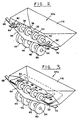
- the inserting station 20 includes a supporting deck 26 and a pair of envelope feed rollers 28 and 30 for feeding an envelope 24b to the position occupied by the envelope 24a. Downstream of the rollers 28 and 30 are a fixed, upper shaft 32 and a vertically translatable, lower, drive shaft 34.
- the upper shaft 32 supports four, spaced feed rollers 36, 38, 40 and 42 rotatably secured thereto (see Figs.
- the lower shaft 34 supports four spaced, cooperating drive rollers 44, 46, 48 and 50 respectively fixedly secured to the drive shaft 34.
- the shaft 34 is mounted in such manner that the drive rollers 44, 46, 48 and 50 can be raised and lowered selectively.
- a bending roll 52 Downstream of the shafts 32 and 34 is a bending roll 52. forming part of, and arranged at one end of, a conveyor 350, the roll 52 comprising individual spaced-apart rollers as shown in Figs. 5 and 6, and further downstream is vertically translatable envelope stop 54.
- a pair of pivotable hold-down fingers 60 and 62 are situated between the shafts 32 and 34 and above the envelope flap and function, as explained in further detail hereinbelow, to press down on the envelope flap 64 and open the mouth of the envelope.
- a pair of flippers 68 and 70 are situated beneath the hold-down fingers 60 and 62 (Figs. 5 and 9, Figs. 2 and 3 showing the flippers purely diagrammatically), which cooperate with the fingers 60 and 62 respectively to effect the opening of the mouth of the envelope 24a as explained in further detail hereinbelow.
- each flipper is made from a piece of strip-like metal having a pair of downwardly bent side lugs 68a, 68b, through which a pivot shaft 400, held in suitable supports 112, 114, (Fig. 10) located slightly inside the outside edges of the envelope and under the envelope flap 64, passes to enable the flipper to pivot about the axis of shaft 400, against the return bias of torsion spring 401, between a normally inoperative position shown in Figs. 5 and 10 and an operative position shown in Figs. 6 and 11 in which the envelope throat is opened.
- the flipper 68 has an inboard leg 68c that is located inwardly of the pivot axis of the flipper and an outboard leg 68d that is located outwardly of the pivot axis.
- the inboard leg carries a gripping pad 402 at its inner end whose function is described below.
- This pad as shown in Fig. 10, is mounted on an offset angled end portion of the flipper at its inboard end, so that a step 68e is formed adjacent the inner end of the inboard leg 68c.
- the pad 402 is made of polyurethane.
- the flipper 70 is correspondingly constructed and its step is shown at 70e in Fig. 10.
- the paper documents 22 which are to be inserted into the waiting envelope 24a are fed by upstream feed apparatus (not shown), such as folding rollers along a chute 72 toward a pair of insert feed rollers 74 and 76 which continue to feed the documents 22 through the opening between the upper rollers 36, 38, 40 and 42 and the lower rollers 44, 46, 48 and 50, which latter are lowered at this time.
- upstream feed apparatus such as folding rollers along a chute 72 toward a pair of insert feed rollers 74 and 76 which continue to feed the documents 22 through the opening between the upper rollers 36, 38, 40 and 42 and the lower rollers 44, 46, 48 and 50, which latter are lowered at this time.
- the momentum given the documents 22 by the feed rollers 36, 38, 40 and 42 due to a leaf spring diagrammatically shown at 290 urging the documents from below against these feed rollers, conveys the documents 22 into the waiting envelope 24a.
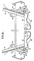
- the insert station 20 further includes a pair of pivotable support arms 80 which rotatably support, at their lower ends, a rotatable shaft 82.
- a pair of opening horns 84 and 86 are fixedly secured to the laterally extending shaft 82.
- At the opposite ends of the shaft 82 are a pair of link members 83 each fixedly secured at one end to the shaft 82 and at the other end rotatably secured to a pin 85.
- Each of the pins 85 travels in groove 88 of a guide member 90 fixedly secured to a bracket 93 (see Fig. 4).
- the major portion of the groove 88 consists of a straight slot section 92 at its upstream end, while the minor portion of the groove 88 concludes at its downstream end with an angled slot section 94 whose axis is oriented at an angle of about 50 to 70 degrees with the axis of the straight slot section 92.
- the purpose of the angled slot section 94 will be discussed in greater detail hereinbelow.
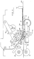
- the envelope feed rollers 28 and 30 cooperate to feed an envelope from the position occupied by envelope 24b (see Figure 9) to the position occupied by envelope 24a against the envelope stop 54 in the down position.
- the drive rollers 44, 46, 48 and 50 are lowered from the feed rollers 36, 38, 40 and 42 respectively, just before the envelope strikes the stop 54.
- the hold-down fingers 60 and 62 are in a raised position to allow the envelope to pass thereunder, and the flippers 68 and 70 are in a position where their interior ends respectively are raised.
- the waiting envelope at the insertion station is supported in a substantially horizontal orientation on the upper surface of conveyor 350.
- the hold-down fingers 60 and 62 are rotated downward to the positions seen in Figs. 6, 11 and 12 against the flippers 68 and 70 respectively, which are thereby caused to pivot against the bias of their torsion springs and pucker the envelope 24a, i.e. the envelope front panel 118 (address bearing panel) is separated from the back panel 116 (see Fig. 11). In this way, the flap 64 is forced downward and the envelope 24a is puckered, causing it to open.
- the envelope is opened by the combined action of firstly the step-like deformation to the envelope flap produced by the interaction between the flipper steps 68e, 70e and the hold-down fingers 60, 62, and secondly the deflection to the portion of the envelope flap located outboard of the corresponding finger 60,62 and in contact with the inboard and outboard legs (68c, 68d of flipper 68), resulting from the pivoting of the flippers 68, 70 (Fig. 12).
- the envelope can reliably be opened without reverse throating of the envelope.
- the hold-down fingers 60, 62 press the envelope flap 64a downwardly against the upper surfaces of drive rollers 44, 46, 48, 50, as shown in Figs 11 and 12, so as to arch the front panel of the envelope downwardly, across the upper surface of bending roll 52. This arching helps to ensure that the front and rear envelope panels separate and that the rear panel pops upwardly rather than downwardly.
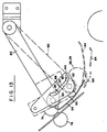
- the pivotable supports 80 are rotated about 38 degrees counter-clockwise by a rack 120 and pinion gear 122 from the position seen in Fig. 11 to the position seen in Fig. 14.
- the counter-clockwise rotation of the supports 80 causes the shaft 82 to move the link members 83 counter-clockwise which drives the pins 85 down the grooves 88 in the straight slot sections 92 and then up into the angled slot sections 94.
- the back panel 116 is raised further upwardly to virtually guarantee that the enclosure documents 22 have free entry into the envelope 24a.
- the path of travel of the horns 84 and 86 causes the horns 84 and 86 to be dropped onto the open flap 64.
- the first contact point is before the smallest throat of the smallest envelope to be handled.
- the horns 84 and 86 then are caused to slide down the inside back surface of the envelope, i.e. the flap 64 and the front panel 118, until the horns 84 and 86 have passed beyond the deepest throat opening to be handled.
- the horns 84 and 86 are then caused to be raised until the envelope 24a is positively opened, as seen in Fig. 14.
- the enclosure documents 22 are being fed along the chute 72 toward the insert feed rollers 74 and 76 which convey the documents 22 to the feed rollers 36, 38, 40 and 42.
- the leaf spring 190 holds the enclosure documents 22 in driving contact with the upper feed rollers 36, 38, 40 and 42, the lower drive rollers 44, 46, 48 and 50 being in their lowered position.
- the feed rollers 36, 38, 40 and 42 convey the enclosure documents 22 into the waiting envelope 24a, as seen in Fig. 15.
- the time for this insertion. process to occur is approximately 400 to 500 milliseconds.
- the inboard friction pads on the flippers prevents the back panel of the envelope being pushed forward as the enclosure documents 22 are driven into the waiting envelope.
- the horns 84 and 86 are shaped so that they will pass under the shaft 32 on the outside of the rollers 36 and 42. (see Fig. 7), but close enough to the rollers 36 and 42 to be inside the smallest envelope to be handled. If desired, a third horn could be located on the centerline between the rollers 38 and 40.
- the envelope opening apparatus can function well with only a single support 80, a single link member 83, a single pin 85 and a single groove 88.
- the vertically translatable envelope stop 54 is caused to be raised (by means not shown).
- both the hold down fingers and the lower rollers 44, 46, 48 and 50 are raised to release the filled envelope, which is transported from the insertion station 20 along the upper surface of the conveyor 350 to exit the inserter into a collection bin or the like, diagrammatically shown at 259 in Figure 1.
- the inserter is versatile in operation and can be set so as to feed a single sheet, or a plurality of sheets, with or without folding, in each case with or without one or more inserts.
- the inserter can be used to place other documents, such as an insert or plurality of inserts only, within the envelope.
Landscapes
- Supplying Of Containers To The Packaging Station (AREA)
Applications Claiming Priority (2)
| Application Number | Priority Date | Filing Date | Title |
|---|---|---|---|
| GB9805902 | 1998-03-19 | ||
| GBGB9805902.5A GB9805902D0 (en) | 1998-03-19 | 1998-03-19 | Envelope opening apparatus |
Publications (2)
| Publication Number | Publication Date |
|---|---|
| EP0943458A1 true EP0943458A1 (de) | 1999-09-22 |
| EP0943458B1 EP0943458B1 (de) | 2003-01-15 |
Family
ID=10828888
Family Applications (1)
| Application Number | Title | Priority Date | Filing Date |
|---|---|---|---|
| EP19990104094 Expired - Lifetime EP0943458B1 (de) | 1998-03-19 | 1999-03-18 | Vorrichtung zum Öffnen eines Briefumschlages |
Country Status (3)
| Country | Link |
|---|---|
| EP (1) | EP0943458B1 (de) |
| DE (1) | DE69904867T2 (de) |
| GB (1) | GB9805902D0 (de) |
Cited By (3)
| Publication number | Priority date | Publication date | Assignee | Title |
|---|---|---|---|---|
| EP1270266A3 (de) * | 2001-06-20 | 2003-09-17 | Pitney Bowes Technologies GmbH | Hilfseinschubanordnung für Briefumschlagfüllmaschinen |
| US20130152514A1 (en) * | 2010-05-07 | 2013-06-20 | Boewe Systec Gmbh | Apparatus and method for inserting one or more goods into a moveable cover |
| EP2746060A1 (de) | 2012-12-20 | 2014-06-25 | BÖWE SYSTEC GmbH | Kuvertierer und Verfahren zum Öffnen eines Kuvertmunds eines entlang eines Kuvertkanals transportierten Kuverts |
Citations (6)
| Publication number | Priority date | Publication date | Assignee | Title |
|---|---|---|---|---|
| WO1993017880A1 (en) * | 1992-03-06 | 1993-09-16 | Printed Forms Equipment Limited | Envelope opening mechanism for inserter apparatus |
| US5251425A (en) * | 1991-03-12 | 1993-10-12 | Kern Ag | Enveloping device |
| EP0604918A1 (de) * | 1992-12-28 | 1994-07-06 | Juki Corporation | Vorrichtung zum Verbreiten von Brieföffnungen für eine Maschine zum Verschliessen und zum Einfüllen von Bogen |
| EP0700794A1 (de) | 1994-09-12 | 1996-03-13 | Pitney Bowes PLC | Apparat zur Behandlung z.B. von Poststücken |
| EP0785092A1 (de) | 1996-01-18 | 1997-07-23 | Pitney Bowes Inc. | Briefumschlagöffnungsvorrichtung |
| EP0785093A1 (de) * | 1996-01-18 | 1997-07-23 | Pitney Bowes Inc. | Öffnungsfinger für Kuvertiervorrichtung |
-
1998
- 1998-03-19 GB GBGB9805902.5A patent/GB9805902D0/en not_active Ceased
-
1999
- 1999-03-18 DE DE1999604867 patent/DE69904867T2/de not_active Expired - Fee Related
- 1999-03-18 EP EP19990104094 patent/EP0943458B1/de not_active Expired - Lifetime
Patent Citations (6)
| Publication number | Priority date | Publication date | Assignee | Title |
|---|---|---|---|---|
| US5251425A (en) * | 1991-03-12 | 1993-10-12 | Kern Ag | Enveloping device |
| WO1993017880A1 (en) * | 1992-03-06 | 1993-09-16 | Printed Forms Equipment Limited | Envelope opening mechanism for inserter apparatus |
| EP0604918A1 (de) * | 1992-12-28 | 1994-07-06 | Juki Corporation | Vorrichtung zum Verbreiten von Brieföffnungen für eine Maschine zum Verschliessen und zum Einfüllen von Bogen |
| EP0700794A1 (de) | 1994-09-12 | 1996-03-13 | Pitney Bowes PLC | Apparat zur Behandlung z.B. von Poststücken |
| EP0785092A1 (de) | 1996-01-18 | 1997-07-23 | Pitney Bowes Inc. | Briefumschlagöffnungsvorrichtung |
| EP0785093A1 (de) * | 1996-01-18 | 1997-07-23 | Pitney Bowes Inc. | Öffnungsfinger für Kuvertiervorrichtung |
Cited By (4)
| Publication number | Priority date | Publication date | Assignee | Title |
|---|---|---|---|---|
| EP1270266A3 (de) * | 2001-06-20 | 2003-09-17 | Pitney Bowes Technologies GmbH | Hilfseinschubanordnung für Briefumschlagfüllmaschinen |
| US20130152514A1 (en) * | 2010-05-07 | 2013-06-20 | Boewe Systec Gmbh | Apparatus and method for inserting one or more goods into a moveable cover |
| EP2746060A1 (de) | 2012-12-20 | 2014-06-25 | BÖWE SYSTEC GmbH | Kuvertierer und Verfahren zum Öffnen eines Kuvertmunds eines entlang eines Kuvertkanals transportierten Kuverts |
| US10160256B2 (en) | 2012-12-20 | 2018-12-25 | Boewe Systec Gmbh | Inserter and method for opening an envelope throat of an envelope transported along an envelope channel |
Also Published As
| Publication number | Publication date |
|---|---|
| DE69904867D1 (de) | 2003-02-20 |
| EP0943458B1 (de) | 2003-01-15 |
| GB9805902D0 (en) | 1998-05-13 |
| DE69904867T2 (de) | 2003-09-11 |
Similar Documents
| Publication | Publication Date | Title |
|---|---|---|
| EP0943460B1 (de) | Kuvertiervorrichtung | |
| US3568401A (en) | Machines for inserting paper sheets into envelopes | |
| EP0785093B1 (de) | Öffnungsfinger für Kuvertiervorrichtung | |
| US5251425A (en) | Enveloping device | |
| US7454882B2 (en) | Methods for variably opening envelopes | |
| EP2123474B1 (de) | Verfahren und Vorrichtung zum Einlegen einer Postsendung in einen Umschlag | |
| US3550351A (en) | Device for transporting envelopes and the like | |
| PL144985B1 (en) | Apparatus for opening envelopes | |
| US6098374A (en) | Envelope opening apparatus | |
| EP0785092B1 (de) | Briefumschlagöffnungsvorrichtung | |
| US6948540B2 (en) | Envelope sealing apparatus | |
| US7819395B2 (en) | Selective drive mechanism | |
| EP0943458B1 (de) | Vorrichtung zum Öffnen eines Briefumschlages | |
| US4888938A (en) | Envelope throat opening blade | |
| EP0633842B1 (de) | Briefumschlagöffnungsmechanismus für kuvertiervorrichtung | |
| EP1935666B1 (de) | Beweglicher Versiegeler | |
| EP0943461B1 (de) | Kuvertiervorrichtung | |
| EP1676719B1 (de) | Führungselement in einer kompakten Kuvertiermaschine | |
| EP0943457B1 (de) | Vorrichtung zum Transport von Dokumenten | |
| JP2922679B2 (ja) | 封入封緘機 | |
| JP2922678B2 (ja) | 封入封緘機 | |
| EP1676716B1 (de) | Falzen und Führen in einer kompakten Kuvertiermaschine | |
| JP3104169B2 (ja) | 自動封書作成装置 | |
| WO2002090127A1 (en) | Device for folding and inserting paper sheets into an envelope |
Legal Events
| Date | Code | Title | Description |
|---|---|---|---|
| PUAI | Public reference made under article 153(3) epc to a published international application that has entered the european phase |
Free format text: ORIGINAL CODE: 0009012 |
|
| AK | Designated contracting states |
Kind code of ref document: A1 Designated state(s): DE FR GB |
|
| AX | Request for extension of the european patent |
Free format text: AL;LT;LV;MK;RO;SI |
|
| 17P | Request for examination filed |
Effective date: 20000308 |
|
| AKX | Designation fees paid |
Free format text: DE FR GB |
|
| GRAG | Despatch of communication of intention to grant |
Free format text: ORIGINAL CODE: EPIDOS AGRA |
|
| 17Q | First examination report despatched |
Effective date: 20020306 |
|
| GRAG | Despatch of communication of intention to grant |
Free format text: ORIGINAL CODE: EPIDOS AGRA |
|
| GRAH | Despatch of communication of intention to grant a patent |
Free format text: ORIGINAL CODE: EPIDOS IGRA |
|
| GRAH | Despatch of communication of intention to grant a patent |
Free format text: ORIGINAL CODE: EPIDOS IGRA |
|
| GRAA | (expected) grant |
Free format text: ORIGINAL CODE: 0009210 |
|
| AK | Designated contracting states |
Kind code of ref document: B1 Designated state(s): DE FR GB |
|
| REG | Reference to a national code |
Ref country code: GB Ref legal event code: FG4D |
|
| REF | Corresponds to: |
Ref document number: 69904867 Country of ref document: DE Date of ref document: 20030220 Kind code of ref document: P |
|
| ET | Fr: translation filed | ||
| PLBE | No opposition filed within time limit |
Free format text: ORIGINAL CODE: 0009261 |
|
| STAA | Information on the status of an ep patent application or granted ep patent |
Free format text: STATUS: NO OPPOSITION FILED WITHIN TIME LIMIT |
|
| 26N | No opposition filed |
Effective date: 20031016 |
|
| PGFP | Annual fee paid to national office [announced via postgrant information from national office to epo] |
Ref country code: GB Payment date: 20080327 Year of fee payment: 10 |
|
| PGFP | Annual fee paid to national office [announced via postgrant information from national office to epo] |
Ref country code: FR Payment date: 20080317 Year of fee payment: 10 Ref country code: DE Payment date: 20080430 Year of fee payment: 10 |
|
| GBPC | Gb: european patent ceased through non-payment of renewal fee |
Effective date: 20090318 |
|
| REG | Reference to a national code |
Ref country code: FR Ref legal event code: ST Effective date: 20091130 |
|
| PG25 | Lapsed in a contracting state [announced via postgrant information from national office to epo] |
Ref country code: DE Free format text: LAPSE BECAUSE OF NON-PAYMENT OF DUE FEES Effective date: 20091001 |
|
| PG25 | Lapsed in a contracting state [announced via postgrant information from national office to epo] |
Ref country code: GB Free format text: LAPSE BECAUSE OF NON-PAYMENT OF DUE FEES Effective date: 20090318 Ref country code: FR Free format text: LAPSE BECAUSE OF NON-PAYMENT OF DUE FEES Effective date: 20091123 |