EP0943281A2 - Versorgungsvorrichtung für einen in mittlerer Höhe eingebautens Sprüharm - Google Patents
Versorgungsvorrichtung für einen in mittlerer Höhe eingebautens Sprüharm Download PDFInfo
- Publication number
- EP0943281A2 EP0943281A2 EP99100436A EP99100436A EP0943281A2 EP 0943281 A2 EP0943281 A2 EP 0943281A2 EP 99100436 A EP99100436 A EP 99100436A EP 99100436 A EP99100436 A EP 99100436A EP 0943281 A2 EP0943281 A2 EP 0943281A2
- Authority
- EP
- European Patent Office
- Prior art keywords
- rack
- spray arm
- feed tube
- pump
- spray
- Prior art date
- Legal status (The legal status is an assumption and is not a legal conclusion. Google has not performed a legal analysis and makes no representation as to the accuracy of the status listed.)
- Granted
Links
Images

Classifications
-
- A—HUMAN NECESSITIES
- A47—FURNITURE; DOMESTIC ARTICLES OR APPLIANCES; COFFEE MILLS; SPICE MILLS; SUCTION CLEANERS IN GENERAL
- A47L—DOMESTIC WASHING OR CLEANING; SUCTION CLEANERS IN GENERAL
- A47L15/00—Washing or rinsing machines for crockery or tableware
- A47L15/42—Details
- A47L15/4214—Water supply, recirculation or discharge arrangements; Devices therefor
- A47L15/4219—Water recirculation
- A47L15/4221—Arrangements for redirection of washing water, e.g. water diverters to selectively supply the spray arms
-
- A—HUMAN NECESSITIES
- A47—FURNITURE; DOMESTIC ARTICLES OR APPLIANCES; COFFEE MILLS; SPICE MILLS; SUCTION CLEANERS IN GENERAL
- A47L—DOMESTIC WASHING OR CLEANING; SUCTION CLEANERS IN GENERAL
- A47L15/00—Washing or rinsing machines for crockery or tableware
- A47L15/14—Washing or rinsing machines for crockery or tableware with stationary crockery baskets and spraying devices within the cleaning chamber
- A47L15/16—Washing or rinsing machines for crockery or tableware with stationary crockery baskets and spraying devices within the cleaning chamber with rigidly-mounted spraying devices
-
- A—HUMAN NECESSITIES
- A47—FURNITURE; DOMESTIC ARTICLES OR APPLIANCES; COFFEE MILLS; SPICE MILLS; SUCTION CLEANERS IN GENERAL
- A47L—DOMESTIC WASHING OR CLEANING; SUCTION CLEANERS IN GENERAL
- A47L15/00—Washing or rinsing machines for crockery or tableware
- A47L15/14—Washing or rinsing machines for crockery or tableware with stationary crockery baskets and spraying devices within the cleaning chamber
- A47L15/18—Washing or rinsing machines for crockery or tableware with stationary crockery baskets and spraying devices within the cleaning chamber with movably-mounted spraying devices
- A47L15/22—Rotary spraying devices
- A47L15/23—Rotary spraying devices moved by means of the sprays
Definitions
- This invention relates to washers in general and, more particularly, to feed systems for middle-level spray arms in domestic dishwashers.
- washers such as domestic dishwashers
- a tub defining a wash chamber with a front opening.
- upper and lower wire racks are disposed within the wash chamber to hold objects to be washed.
- the upper and lower racks are horizontally movable through the front opening to provide access to the objects.
- the lower spray arm is rotatably mounted to a hub below the lower rack, while the upper spray arm is rotatably mounted to a top wall of the tub.
- the lower and upper spray arms are respectively provided with wash liquid through fixed lower and upper feed systems.
- the lower feed system extends through the hub, while the upper feed system extends along a side wall of the tub up to the top wall.
- Milocco-type system uses a head of wash liquid in an upper feed system to help actuate a valve for switching wash liquid between the lower and upper spray arms.
- the middle-level spray arm is rotatably mounted to an underside of the upper rack and is fed by a middle-level feed system. Since the upper rack in a washer is horizontally movable and is typically connected to the middle-level spray arm, the middle-level spray arm is usually disconnectable from the middle-level feed system.
- the middle-level feed system includes a vertically-extendible tower, which is connected to the lower feed system and extends upward from the hub.
- the tower extends up to, and engages, the middle-level spray arm to provide the middle-level spray arm with wash liquid.
- the tower retracts and disconnects from the middle-level spray arm.
- the middle-level feed system includes a nozzle located at the center of the top wall and a funnel spaced below the nozzle.
- the funnel extends through the upper rack and is connected to the middle-level spray arm.
- the funnel collects wash liquid from the nozzle and transmits the wash liquid to the middle-level spray arm.
- the funnel takes up space in the upper rack that could be used to hold more objects.
- the washer includes a tub having a bottom wall, a rear wall, a top wall and a side wall.
- the tub defines a wash chamber and a sump for collecting liquid.
- First and second racks are provided for holding objects to be washed in the wash chamber.
- the first rack is disposed below the second rack.
- First and second spray arms are provided for spraying liquid onto the first and second racks.
- the first spray arm is disposed below the first rack.
- a pump is provided for moving liquid from the sump to the first and second spray arms.
- a feed system is provided for conveying liquid from the pump to the second spray arm.
- the feed system extends along the top wall, the side wall, and the rear wall of the tub.
- a tub having a bottom wall, a rear wall, a top wall and a side wall.
- the tub defines a wash chamber and a sump for collecting liquid.
- Upper and lower racks are provided for holding objects to be washed in the wash chamber.
- a lower spray arm is provided for spraying liquid onto the lower rack.
- the lower spray arm is disposed below the lower rack.
- a middle-level spray arm is included for spraying liquid onto the upper rack.
- the middle-level spray arm is disposed below the upper rack.
- a pump is provided for moving liquid from the sump to the lower and middle-level spray arms.
- a valve is included for alternating liquid flow between the lower spray arm and the middle-level spray arm.
- the valve includes a housing and a closing element.
- the housing has first and second outlets, and an inlet connected to the pump.
- the closing element is disposed within the housing and is movable between a plurality of positions in response to starting and stopping of the pump. The positions include a first blocking position, wherein the closing element partially closes the second outlet and a second blocking position wherein the closing element closes the first outlet.
- a lower feed system connects the first outlet of the valve to the lower spray arm, and a middle-level feed system connects the second outlet of the valve to the middle-level spray arm.
- a washer including a tub having a bottom wall, a rear wall, a top wall and a side wall.
- the tub defines a wash chamber and a sump for collecting liquid.
- First and second racks are provided for holding objects to be washed in the wash chamber.
- the first rack is disposed below the second rack.
- First and second spray arms are provided for spraying liquid onto the first and second racks.
- the first spray arm is disposed below the first rack.
- a pump is included for moving liquid from the sump to the first and second spray arms.
- a feed system is provided for conveying liquid from the pump to the second spray arm.
- the feed system includes an interior tube having spaced-apart upper and lower arms, between which is disposed the second rack.
- a tub having a bottom wall, a rear wall, a top wall and a side wall.
- the tub defines a wash chamber and a sump for collecting liquid.
- First and second racks are provided for holding objects to be washed in the wash chamber.
- the first rack is disposed below the second rack.
- First and second spray arms are included for respectively spraying liquid onto the first and second racks.
- the first spray arm is disposed below the first rack.
- a spray nozzle is included for spraying liquid onto the second rack.
- a pump is provided for moving liquid from the sump to the first and second spray arms.
- First and second feed tubes are provided for conveying liquid from the pump to the second spray arm. The first and second feed tubes are connected together by the spray nozzle.
- a washer 10 such as a domestic dishwasher.
- the washer 10 washes objects, such as dishes, with a wash liquid, such as detergent and water.
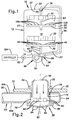
- the washer 10 includes a molded plastic tub 12 defining a sump 14 and a wash chamber 16 with a front access opening.
- the front access opening is closed by a horizontally-pivoting door (not shown).
- the tub 12 has a top wall 20, opposing side walls 22, a bottom wall 23, and a rear wall 24 (shown best in Fig. 3).
- the rear wall 24 has a pair of upper bosses 26 and a pair of lower bosses 28 molded therein. Each of the upper and lower bosses 26, 28 defines a threaded bore.
- Upper and lower racks 30, 32 are disposed in the wash chamber 16 for holding objects to be washed, such as dishes, silverware, glasses and cookware.
- the upper and lower racks 30, 32 are each generally basket-shaped and have a wire frame construction.
- the upper rack 30 is movably supported on tracks (not shown) secured to the side walls 22 of the tub 12, while the lower rack 32 is fitted with rollers adapted to track on side wall ridges (not shown) formed in the tub 12.
- a middle-level spray arm 34 is disposed below the upper rack 30, while a lower spray arm 36 is disposed below the lower rack 32.
- An upper spray nozzle 38 is disposed above the upper rack 30.
- the washer 10 utilizes a Milocco-type system for alternating a flow of wash liquid between the lower spray arm 36 and the middle-level spray arm 34.
- the sump 14 is positioned at the bottom of the tub 12, below the wash chamber 16.
- the sump 14 collects and holds wash liquid falling from the wash chamber 16.
- a hub 40 extends upward from the sump 14 and has a lower feed passage 42 extending therethrough.
- the lower spray arm 36 is rotatably mounted to the hub 40.
- the lower spray arm 36 is substantially hollow and has oppositely-directed arm portions.
- a central opening (not shown) is formed in a bottom surface of the lower spray arm 36 and overlays the lower feed passage 42.
- a top surface of the lower spray arm 36 defines a plurality of upwardly-directed openings or wash jets 46 through which sprays of wash liquid may project.
- An inlet to a pump 48 is disposed in the sump 14.
- the pump 48 has an impeller 50 driven by an electric motor 52.
- An outlet 54 from the pump 48 is connected to a valve 56 which alternately directs wash liquid to the lower feed passage 42 and a middle-level feed system 57 comprised of the spray nozzle 38, a first, or side, feed tube 58, and a second, or rear, feed tube 60.
- a first outlet 62 of the valve 56 is connected to the lower feed passage 42, while a second outlet 66 of the valve 56 is connected to the side feed tube 58.
- the side feed tube 58 has a C-shaped configuration.
- the side feed tube 58 has a generally rectangular cross-section.
- the side feed tube 58 extends laterally from the valve 56 and runs along the bottom wall 23 of the tub 12.
- the side feed tube 58 then bends and extends upwardly along one of the side walls 22 of the tub 12.
- the side feed tube 58 bends again and runs along the top wall 20.
- the side feed tube 58 bends downward and extends into a top opening formed in the top wall 20.
- a circumferential flange 70 (shown in Fig. 2) on the side feed tube 58 adjoins an outer surface 72 of the top wall 20 around the top opening.
- the side feed tube 58 terminates at a threaded outlet end 74, which is connected to the rear feed tube 60 by the spray nozzle 38.
- the spray nozzle 38 is generally cylindrical and includes a side wall 76 and top and bottom ends 78, 80.
- the side wall 76 defines a plurality of openings 82 and is threaded at the top end 78.
- the top end 78 is open, while the bottom end 80 is convex and defines a plurality of small apertures 84.
- a flange 86 with an L-shaped cross-section extends radially outward from the side wall 76, toward the bottom end 80.
- the rear feed tube 60 has a generally C-shaped configuration.
- the rear feed tube 60 has a generally rectangular cross-section.
- the rear feed tube 60 includes a central member 88 joined between spaced-apart upper and lower arms 90, 92.
- the upper and lower arms 90, 92 respectively have closed ends 94, 96.
- An enlarged opening is formed in a top surface 90a of the upper arm 90 and an enlarged opening is formed in a bottom surface 90b of the upper arm 90.
- the enlarged openings are located toward the end 94 and are aligned so as to form a vertical passage through the upper arm 90.
- the spray nozzle 38 extends into the passage of the upper arm 90 through the opening in the bottom surface 90b, while the side feed tube 58 extends into the passage through the opening in the top surface 90a.
- the spray nozzle 38 extends into the passage such that an upper edge of the flange 86 abuts the bottom surface of the upper arm 90 around the opening therein.
- the top end 78 of the spray nozzle 38 is threadably secured to the outlet end 74 of the side feed tube 58, thereby trapping the upper arm 90 between the flange 86 of the spray nozzle 38 and the top wall 20 of the tub 12.
- the spray nozzle 38 securely connects the side feed tube 58 to the rear feed tube 60 so as to form the middle-level feed system 57.
- the openings 82 in the side wall 76 of the spray nozzle 38 permit wash liquid to travel from the side feed tube 58 to the rear feed tube 60.
- the upper arm 90 of the rear feed tube 60 extends rearwardly from the spray nozzle 38 and runs along an interior surface of the top wall 20 of the tub 12.
- the upper arm 90 joins the central member 88 at an upper bend 98.
- the central member 88 extends downwardly from the upper bend 98 and runs along an interior surface of the rear wall 24 of the tub 12.
- Below the upper rack 30, the central member 88 joins the lower arm 92 at a lower bend 100.
- the lower arm 92 extends forwardly from the lower bend 100 and is spaced below the upper rack 30. In this manner, the rear feed tube 60 extends around the rear of the upper rack 30 so as to permit the upper rack 30 to be moved horizontally forward through the front access opening of the tub 12.
- a pair of upper mounting flanges 102 are molded into opposing side surfaces of the central member 88 of the rear feed tube 60, toward the upper bend 98, while a pair of lower mounting flanges 104 are molded into the side surfaces, toward the lower bend 100.
- the upper and lower mounting flanges 102, 104 have substantially the same construction.
- the upper and lower mounting flanges 102, 104 extend laterally from the side surfaces and have mounting holes formed therein.
- the upper mounting flanges 102 are secured to the upper bosses 26 of the rear wall 24 of the tub 12 by screws 106 that extend through the mounting holes and are threadably received in the bores of the upper bosses 26.
- the lower mounting flanges 104 are secured to the lower bosses 28 of the rear wall 24 by screws 108 that extend through the mounting holes and are threadably received in the bores of the lower bosses 28. In this manner, the central member 88 of the rear feed tube 60 is secured to the rear wall 24 of the tub 12.
- the lower arm 92 of the rear feed tube 60 extends underneath the upper rack 30 for approximately half the depth of the upper rack 30 and then terminates at the end 96.
- An outlet opening is formed in a top surface 92a of the lower arm 92, toward the end 96.
- the middle-level spray arm 34 is rotatably mounted to the lower arm 92 over the outlet opening.
- the middle-level spray arm 34 is supported in a spaced manner from the upper rack 30, thereby permitting the upper rack 30 to be moved horizontally forward without disconnecting the middle-level spray arm 34 from its source of wash liquid.
- the middle-level spray arm 34 is substantially hollow and has oppositely-directed arm portions. A central opening is formed in a bottom surface of the middle-level spray arm 34 and overlays the outlet opening in the lower arm 92. A top surface of the middle-level spray arm 34 defines a plurality of upwardly-directed openings or wash jets 109 through which sprays of wash liquid may project.
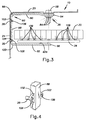
- valve 56 is shown as it appears when the pump 48 has been idle for an extended period of time.
- the valve 56 defines an inner chamber 110 and has the first outlet 62, the second outlet 66 and an inlet 112 connected to the pump 48.
- a bypass channel 114 leads from the inlet 112 to an outer portion of the second outlet 66.
- the bypass channel 114 has a cross-sectional area substantially smaller than either the first or second outlets 62, 66.
- a spherical closing element 116 resting on a guide 118 that slopes downward from an upper end 120 located below the first outlet 62 to a lower end 122 located below the second outlet 66.
- the closing element 116 is made from a material having a specific gravity greater than the wash liquid, such as stainless steel. Accordingly, the closing element 116 naturally gravitates towards the lower end 122.
- the closing element 116 is stable and is not blocking either the second outlet 66 or the first outlet 62, i.e., the closing element 116 is in a stable unblocking position. In the stable unblocking position, the closing element 116 is aligned below the second outlet 66.
- the valve 56 operates to alternately direct wash liquid from the pump 48 to the lower feed passage 42 and the middle-level feed system 57.
- the valve 56 operates in response to a cycling of the pump 48 through four phases: a first phase of operation, a first phase of non-operation, a second phase of operation and a second phase of non-operation.
- the cycling of the pump 48 is accomplished by a controller 124 (shown in Fig. 1), which starts and stops the motor 52 (shown in Fig. 1).
- the controller 124 is an electro-mechanical or electronic controller 124 known in the prior art.
- An example of such an electro-mechanical controller 124 is the controller 124 disclosed in U.S. Patent No. 5,494,062 to Springer, which is incorporated herein by reference.
- the closing element 116 is in the stable unblocking position when the pump 48 has been idle for an extended period of time.
- the pump 48 enters the first phase of operation.
- the pump 48 directs wash liquid against the closing element 116, moving the closing element 116 from the stable unblocking position to a first blocking position shown in Fig. 6.
- the closing element 116 is pressed against the inner portion of the second outlet 66, substantially blocking the flow of wash liquid through the second outlet 66.
- most of the wash liquid from the pump 48 flows through the first outlet 62 and the lower feed passage 42, and enters the lower spray arm 36.
- the wash liquid projects through the upwardly-directed wash jets 46 to form a plurality of wash sprays. These wash sprays pass through the bottom of the lower rack 32 and contact the objects being held therein.
- bypass wash liquid enters the side feed tube 58 and fills its volume until the pump 48 is stopped or the hydrostatic pressure exerted by the wash liquid in the side feed tube 58 equals the pressure of the wash liquid entering the side feed tube 58.
- the size of the bypass channel 114 is limited in relation to the capacity of the pump 48 so as to allow the hydrostatic pressure of the wash liquid in the side feed tube 58 to stop the flow of bypass wash liquid before the bypass wash liquid completely fills the side feed tube 58 and enters the rear feed tube 60 and thence the middle-level spray arm 34.
- bypass channel 114 can be replaced by other arrangements that permit a small amount of wash liquid to bypass the closing element 116 and enter the side feed tube 58.
- the inner portion of the second outlet 66 can be made irregular so that the closing element 116 does not completely seal the inner portion when the closing element 116 is in the first blocking position.
- the pump 48 enters the first phase of non-operation.
- the bypass wash liquid in the side feed tube 58 and the wash liquid in the lower feed passage 42 flow by gravity back into the chamber.
- gravity urges the closing element 116 to move away from the first blocking position of Fig. 6.
- the force of gravity on the closing element 116 would, by itself, move the closing element 116 back to the stable unblocking position.
- the flow of bypass wash liquid from the side feed tube 58 exerts a substantial hydrostatic pressure on the closing element 116 and, instead, moves the closing element 116 to an unstable unblocking position shown in Fig. 7.
- the flow of wash liquid from the lower feed passage 42 also exerts a force on the closing element 116, but this force is minimal since the head of wash liquid in the lower feed passage 42 is small.
- the closing element 116 In the unstable unblocking position, the closing element 116 is resting on the upper end 120 of the guide 118 and is spaced from, but aligned with, the first outlet 62. This position is unstable because the closing element 116 would, absent the flow of bypass wash liquid, slide along the guide 118 and return to the stable unblocking position at the lower end 122 of the guide 118.
- the pump 48 is started by the controller 124 before the expiration of a first period of time, which is the time it takes for the bypass wash liquid to stop flowing from the side feed tube 58. When the pump 48 is again started, the pump 48 enters the second phase of operation.
- the pump 48 directs wash liquid against the closing element 116, moving the closing element 116 from the unstable unblocking position shown in Fig. 7 to a second blocking position shown in Fig. 8.
- the closing element 116 is pressed against the inner portion of the first outlet 62, blocking the flow of wash liquid through the first outlet 62.
- the wash liquid from the pump 48 flows through the second outlet 66 and into the side feed tube 58.
- the wash liquid flows upward through the side feed tube 58 and enters the spray nozzle 38.
- Most of the wash liquid passes through the openings 82 in the side wall 76 of the spray nozzle 38 and enters the rear feed tube 60.
- a portion of the wash liquid passes through the apertures 84 in the bottom end 80 of the spray nozzle 38 and is projected downwardly onto the objects held in the upper rack 30.
- the wash liquid in the rear feed tube 60 flows into the middle-level spray arm 34 and is projected through the upwardly-directed wash jets 109 to form a plurality of wash sprays.
- the wash sprays pass through the bottom of the upper rack 30 and contact the objects being held therein.
- the middle-level feed system 57 fills with wash liquid.
- the pump 48 enters the second phase of non-operation.
- the wash liquid in the side feed tube 58 flows back into the valve 56.
- the wash liquid does not flow into the rear feed tube 60 because of the apertures 84 in the bottom end 80 of the spray nozzle 38.
- the apertures 84 act as an air break that equalizes the pressure at the top of the side feed tube 58 with the pressure in the wash chamber 16.
- the air break permits gravity to move the wash liquid in the side feed tube 58 back into the valve 56.
- the air brake also permits gravity to move the wash liquid in the rear feed tube 60 into the wash chamber 16 through the middle-level spray arm 34.
- the duration of the second phase of non-operation is greater than a second period of time, which is the time it takes for the wash liquid to drain from the side feed tube 58 and for the closing element 116 to subsequently move to the stable unblocking position.
- wash liquid is supplied to the lower spray arm 36 during the first phase of operation of the pump 48 and wash liquid is supplied to the middle-level spray arm 34 and the spray nozzle 38 during the second phase of operation of the pump 48.
- the controller 124 does not have to be programmed to continuously cycle the pump 48 through the four phases so as to continuously alternate the supply of wash liquid between the lower spray arm 36 and the middle-level spray arm 34 and the spray nozzle 38.
- the controller 124 can be programmed to alternate the supply of wash liquid between the lower spray arm 36 and the middle-level spray arm 34 and the spray nozzle 38 for a period of time and then supply only the lower spray arm 36 or the middle-level spray arm 34 for the remainder of the operation of the washer 10, or the controller 124 can be programmed to only supply wash liquid to the lower spray arm 36.
- the foregoing is accomplished by programming the controller 124 to stop progressing the pump 48 to subsequent phases. It should be appreciated, however, that wash liquid cannot be supplied only to the middle-level spray arm 34 and the spray nozzle 38 because the pump 48 has to progress through the first phase of operation and the first phase of non-operation in order to reach the second phase of operation wherein wash liquid is supplied to the middle-level spray arm 34 and the spray nozzle 38.
- the controller 124 can also be programmed to change the duration wash liquid is supplied to the lower spray arm 36 and the middle-level spray arm 34 by changing the durations of the first and second phases of operation.
- the pauses between the changes in supply to the lower spray arm 36 and the middle-level spray arm 34, i.e., the first and second phases of non-operation, can also be changed, but only to an extent.
- the pause between supplying wash liquid to the lower spray arm 36 and supplying wash liquid to the middle-level spray arm 34 and the spray nozzle 38, i.e., the first phase of non-operation cannot be greater than the first period of time. However, the first phase of non-operation can be less than the first period of time.
- the pause between supplying wash liquid to the middle-level spray arm 34 and the spray nozzle 38 and supplying wash liquid to the lower spray arm 36, i.e., the second phase of non-operation, cannot be less than the second period of time.
- the second phase of non-operation can have a duration greater than the second period of time.
- the stopping and starting of the pump 48 to switch the flow of wash liquid from the lower spray arm 36 to the middle-level spray arm 34 and the spray nozzle 38 is the most stringent operating parameter that has to be met by the controller 124 because the time between the stopping and the starting of the pump 48, i.e., the first period of time, is short. Accordingly, the first period of time determines the timing tolerance of the controller 124. Since the first period of time is the time it takes for the bypass wash liquid to stop flowing from the side feed tube 58, the first period of time is a function of the volume of the side feed tube 58.
- the side feed tube 58 extends over the top wall 20 of the tub, the side feed tube 58 has a greater volume than a tube that only extends up to the level of the middle-level spray arm 34 (such a tube hereinafter being referred to as a midway tube). Accordingly, the time it takes for bypass wash liquid to stop flowing from the side feed tube 58 is significantly greater than the time it would take for bypass wash liquid to stop flowing from a midway tube. As a result, the timing tolerance imposed by the side feed tube 58 on the controller 124 is looser than the timing tolerance that would be imposed by a midway tube on the controller 124.
- the side feed tube 58 In addition to imposing a looser timing tolerance than a midway tube, the side feed tube 58 also provides a greater hydrostatic pressure for moving the closing element 116 than a midway tube.
- the head of wash liquid in the side feed tube 58 extends all the way up to the top wall 20 of the tub 12, whereas in a midway tube the head of wash liquid only extends up to the middle-level spray arm 34.
- the hydrostatic pressure produced by the side feed tube 58 easily moves the closing element 116 to the unstable unblocking position during the first phase of non-operation, even if the closing element 116 is partially stuck.
- the hydrostatic pressure produced by a midway tube may not be sufficient to move the closing element 116 to the unstable unblocking position if the closing element 116 is partially stuck.
- the middle-level feed system 57 of the present invention provides numerous benefits. Since the middle-level feed system 57 extends around the upper rack 30 and supports the middle-level spray arm 34, the upper rack 30 can be moved horizontally without disconnecting the middle-level spray arm 34 from the middle-level feed system 57. In addition, the middle-level feed system 57 has a simple construction and is favorably suited for use in the Milocco-type system utilized by the washer 10. The middle-level feed system 57 also does not extend through the upper rack 30 so as to take up space for holding objects to be washed.
Applications Claiming Priority (2)
| Application Number | Priority Date | Filing Date | Title |
|---|---|---|---|
| US2787998A | 1998-02-23 | 1998-02-23 | |
| US27879 | 1998-02-23 |
Publications (3)
| Publication Number | Publication Date |
|---|---|
| EP0943281A2 true EP0943281A2 (de) | 1999-09-22 |
| EP0943281A3 EP0943281A3 (de) | 2000-12-20 |
| EP0943281B1 EP0943281B1 (de) | 2006-09-13 |
Family
ID=21840300
Family Applications (1)
| Application Number | Title | Priority Date | Filing Date |
|---|---|---|---|
| EP19990100436 Expired - Lifetime EP0943281B1 (de) | 1998-02-23 | 1999-01-11 | Versorgungsvorrichtung für einen in mittlerer Höhe eingebautens Sprüharm |
Country Status (3)
| Country | Link |
|---|---|
| EP (1) | EP0943281B1 (de) |
| DE (1) | DE69933161T2 (de) |
| ES (1) | ES2275319T3 (de) |
Cited By (24)
| Publication number | Priority date | Publication date | Assignee | Title |
|---|---|---|---|---|
| EP1120078A1 (de) * | 1999-12-09 | 2001-08-01 | Whirlpool Corporation | Haushalt-Geschirrspülmaschine |
| WO2001082769A1 (en) * | 2000-04-27 | 2001-11-08 | Electrolux Zanussi S.P.A. | Dishwashing machine with improved washing liquor distribution valve |
| EP1277430A1 (de) * | 2001-07-18 | 2003-01-22 | Electrolux Home Products Corporation N.V. | Geschirrspülmaschine mit veränderbarer Flüssigkeitsverteilung |
| EP1312297A2 (de) * | 2001-11-14 | 2003-05-21 | Electrolux Home Products Corporation N.V. | Geschirrspülmaschine |
| DE102004054313A1 (de) * | 2004-11-10 | 2006-05-11 | Electrolux Home Products Corporation N.V. | Verfahren zum Betreiben einer Geschirrspülmaschine und Geschirrspülmaschine zur Durchführung des Verfahrens |
| US7896977B2 (en) | 2007-12-19 | 2011-03-01 | Whirlpool Corporation | Dishwasher with sequencing corner nozzles |
| ITTO20120165A1 (it) * | 2012-02-24 | 2013-08-25 | Premark Feg Llc | Pompa a doppia mandata e macchina lavastoviglie provvista di tale pompa |
| US9295368B2 (en) | 2013-03-01 | 2016-03-29 | Whirlpool Corporation | Dishwasher with hydraulically driven sprayer |
| US9375128B2 (en) | 2011-09-22 | 2016-06-28 | Whirlpool Corporation | Dishwasher with spray system |
| US9414736B2 (en) | 2011-09-22 | 2016-08-16 | Whirlpool Corporation | Dishwasher with directional spray |
| US9492055B2 (en) | 2011-09-22 | 2016-11-15 | Whirlpool Corporation | Dishwasher with spray system |
| US9532701B2 (en) | 2013-03-01 | 2017-01-03 | Whirlpool Corporation | Dishwasher with sprayer |
| US9532699B2 (en) | 2013-07-15 | 2017-01-03 | Whirlpool Corporation | Dishwasher with sprayer |
| US9693672B2 (en) | 2011-09-22 | 2017-07-04 | Whirlpool Corporation | Dishwasher with sprayer |
| US9833120B2 (en) | 2012-06-01 | 2017-12-05 | Whirlpool Corporation | Heating air for drying dishes in a dishwasher using an in-line wash liquid heater |
| US9861251B2 (en) | 2011-06-20 | 2018-01-09 | Whirlpool Corporation | Filter with artificial boundary for a dishwashing machine |
| CN108042075A (zh) * | 2018-01-25 | 2018-05-18 | 芜湖应天光电科技有限责任公司 | 一种节水型洗碗机及其控制系统 |
| US10058228B2 (en) | 2012-02-27 | 2018-08-28 | Whirlpool Corporation | Soil chopping system for a dishwasher |
| US10076226B2 (en) | 2012-05-30 | 2018-09-18 | Whirlpool Corporation | Rotating filter for a dishwasher |
| US10213085B2 (en) | 2013-07-01 | 2019-02-26 | Whirlpool Corporation | Dishwasher for treating dishes |
| US10653291B2 (en) | 2011-06-20 | 2020-05-19 | Whirlpool Corporation | Ultra micron filter for a dishwasher |
| US10779703B2 (en) | 2009-12-21 | 2020-09-22 | Whirlpool Corporation | Rotating drum filter for a dishwashing machine |
| US20230397793A1 (en) * | 2022-06-13 | 2023-12-14 | Whirlpool Corporation | Dishwasher and method of operating |
| US11882977B2 (en) | 2011-05-16 | 2024-01-30 | Whirlpool Corporation | Dishwasher with filter assembly |
Families Citing this family (1)
| Publication number | Priority date | Publication date | Assignee | Title |
|---|---|---|---|---|
| DE102010060248B4 (de) * | 2010-10-29 | 2014-08-07 | Piller Entgrattechnik Gmbh | Vorrichtung zum Einbringen eines Bauteils in eine Restschmutz-Prüfkammer zum Abwaschen der auf dem Bautel haftenden Restschmutzteile |
Citations (6)
| Publication number | Priority date | Publication date | Assignee | Title |
|---|---|---|---|---|
| DE1628600A1 (de) * | 1966-10-01 | 1970-08-20 | Philips Nv | Geschirrspuelmaschine |
| US3538927A (en) * | 1967-04-27 | 1970-11-10 | Electrolux Ab | Dishwashing machine |
| US3809106A (en) * | 1972-08-23 | 1974-05-07 | Fedders Corp | Dishwasher with improved spray apparatus |
| DE4434235C1 (de) * | 1994-09-24 | 1995-12-14 | Bauknecht Hausgeraete | Haushalt-Geschirrspülmaschine |
| US5546968A (en) * | 1993-10-23 | 1996-08-20 | Goldstar Co., Ltd. | Supplementary washing device of a dish washer |
| EP0780086A2 (de) * | 1995-12-22 | 1997-06-25 | White Consolidated Industries, Inc. | Wasser-Zufuhrrohr mit Behälter |
-
1999
- 1999-01-11 EP EP19990100436 patent/EP0943281B1/de not_active Expired - Lifetime
- 1999-01-11 ES ES99100436T patent/ES2275319T3/es not_active Expired - Lifetime
- 1999-01-11 DE DE1999633161 patent/DE69933161T2/de not_active Expired - Lifetime
Patent Citations (6)
| Publication number | Priority date | Publication date | Assignee | Title |
|---|---|---|---|---|
| DE1628600A1 (de) * | 1966-10-01 | 1970-08-20 | Philips Nv | Geschirrspuelmaschine |
| US3538927A (en) * | 1967-04-27 | 1970-11-10 | Electrolux Ab | Dishwashing machine |
| US3809106A (en) * | 1972-08-23 | 1974-05-07 | Fedders Corp | Dishwasher with improved spray apparatus |
| US5546968A (en) * | 1993-10-23 | 1996-08-20 | Goldstar Co., Ltd. | Supplementary washing device of a dish washer |
| DE4434235C1 (de) * | 1994-09-24 | 1995-12-14 | Bauknecht Hausgeraete | Haushalt-Geschirrspülmaschine |
| EP0780086A2 (de) * | 1995-12-22 | 1997-06-25 | White Consolidated Industries, Inc. | Wasser-Zufuhrrohr mit Behälter |
Cited By (38)
| Publication number | Priority date | Publication date | Assignee | Title |
|---|---|---|---|---|
| EP1120078A1 (de) * | 1999-12-09 | 2001-08-01 | Whirlpool Corporation | Haushalt-Geschirrspülmaschine |
| US7114509B2 (en) | 2000-04-27 | 2006-10-03 | Electrolux Home Products Italy S.P.A. | Dishwashing machine with improved washing liquor distribution valve |
| WO2001082769A1 (en) * | 2000-04-27 | 2001-11-08 | Electrolux Zanussi S.P.A. | Dishwashing machine with improved washing liquor distribution valve |
| EP1277430A1 (de) * | 2001-07-18 | 2003-01-22 | Electrolux Home Products Corporation N.V. | Geschirrspülmaschine mit veränderbarer Flüssigkeitsverteilung |
| EP1312297A2 (de) * | 2001-11-14 | 2003-05-21 | Electrolux Home Products Corporation N.V. | Geschirrspülmaschine |
| EP1312297A3 (de) * | 2001-11-14 | 2006-03-01 | Electrolux Home Products Corporation N.V. | Geschirrspülmaschine |
| DE102004054313A1 (de) * | 2004-11-10 | 2006-05-11 | Electrolux Home Products Corporation N.V. | Verfahren zum Betreiben einer Geschirrspülmaschine und Geschirrspülmaschine zur Durchführung des Verfahrens |
| US7896977B2 (en) | 2007-12-19 | 2011-03-01 | Whirlpool Corporation | Dishwasher with sequencing corner nozzles |
| US10779703B2 (en) | 2009-12-21 | 2020-09-22 | Whirlpool Corporation | Rotating drum filter for a dishwashing machine |
| US11882977B2 (en) | 2011-05-16 | 2024-01-30 | Whirlpool Corporation | Dishwasher with filter assembly |
| US10813525B2 (en) | 2011-06-20 | 2020-10-27 | Whirlpool Corporation | Ultra micron filter for a dishwasher |
| US10653291B2 (en) | 2011-06-20 | 2020-05-19 | Whirlpool Corporation | Ultra micron filter for a dishwasher |
| US10314457B2 (en) | 2011-06-20 | 2019-06-11 | Whirlpool Corporation | Filter with artificial boundary for a dishwashing machine |
| US10178939B2 (en) | 2011-06-20 | 2019-01-15 | Whirlpool Corporation | Filter with artificial boundary for a dishwashing machine |
| US9861251B2 (en) | 2011-06-20 | 2018-01-09 | Whirlpool Corporation | Filter with artificial boundary for a dishwashing machine |
| US9693672B2 (en) | 2011-09-22 | 2017-07-04 | Whirlpool Corporation | Dishwasher with sprayer |
| US10602907B2 (en) | 2011-09-22 | 2020-03-31 | Whirlpool Corporation | Dishwasher with sprayer |
| US9375128B2 (en) | 2011-09-22 | 2016-06-28 | Whirlpool Corporation | Dishwasher with spray system |
| US9492055B2 (en) | 2011-09-22 | 2016-11-15 | Whirlpool Corporation | Dishwasher with spray system |
| US9386903B2 (en) | 2011-09-22 | 2016-07-12 | Whirlpool Corporation | Dishwasher with spray system |
| US9402526B2 (en) | 2011-09-22 | 2016-08-02 | Whirlpool Corporation | Dishwasher with spray system |
| US9414736B2 (en) | 2011-09-22 | 2016-08-16 | Whirlpool Corporation | Dishwasher with directional spray |
| US10058229B2 (en) | 2011-09-22 | 2018-08-28 | Whirlpool Corporation | Dishwasher with sprayer |
| WO2013126481A1 (en) * | 2012-02-24 | 2013-08-29 | Premark Feg L.L.C. | Double delivery pump and washing machine provided thereof |
| ITTO20120165A1 (it) * | 2012-02-24 | 2013-08-25 | Premark Feg Llc | Pompa a doppia mandata e macchina lavastoviglie provvista di tale pompa |
| US10058228B2 (en) | 2012-02-27 | 2018-08-28 | Whirlpool Corporation | Soil chopping system for a dishwasher |
| US10076226B2 (en) | 2012-05-30 | 2018-09-18 | Whirlpool Corporation | Rotating filter for a dishwasher |
| US9833120B2 (en) | 2012-06-01 | 2017-12-05 | Whirlpool Corporation | Heating air for drying dishes in a dishwasher using an in-line wash liquid heater |
| US10398283B2 (en) | 2013-03-01 | 2019-09-03 | Whirlpool Corporation | Dishwasher with sprayer |
| US9532701B2 (en) | 2013-03-01 | 2017-01-03 | Whirlpool Corporation | Dishwasher with sprayer |
| US9295368B2 (en) | 2013-03-01 | 2016-03-29 | Whirlpool Corporation | Dishwasher with hydraulically driven sprayer |
| US10213085B2 (en) | 2013-07-01 | 2019-02-26 | Whirlpool Corporation | Dishwasher for treating dishes |
| US10052010B2 (en) | 2013-07-15 | 2018-08-21 | Whirlpool Corporation | Dishwasher with sprayer |
| US9532699B2 (en) | 2013-07-15 | 2017-01-03 | Whirlpool Corporation | Dishwasher with sprayer |
| US9839340B2 (en) | 2013-07-15 | 2017-12-12 | Whirlpool Corporation | Dishwasher with sprayer |
| CN108042075A (zh) * | 2018-01-25 | 2018-05-18 | 芜湖应天光电科技有限责任公司 | 一种节水型洗碗机及其控制系统 |
| US20230397793A1 (en) * | 2022-06-13 | 2023-12-14 | Whirlpool Corporation | Dishwasher and method of operating |
| US11896181B2 (en) * | 2022-06-13 | 2024-02-13 | Whirlpool Corporation | Dishwasher and method of operating |
Also Published As
| Publication number | Publication date |
|---|---|
| ES2275319T3 (es) | 2007-06-01 |
| DE69933161T2 (de) | 2007-09-20 |
| DE69933161D1 (de) | 2006-10-26 |
| EP0943281B1 (de) | 2006-09-13 |
| EP0943281A3 (de) | 2000-12-20 |
Similar Documents
| Publication | Publication Date | Title |
|---|---|---|
| EP0943281B1 (de) | Versorgungsvorrichtung für einen in mittlerer Höhe eingebautens Sprüharm | |
| US8522810B2 (en) | Water diverter valve and related dishwasher | |
| CA1241893A (en) | Dishwashing apparatus and method | |
| US3044842A (en) | Dishwasher | |
| US2734520A (en) | Dishwashing machine | |
| US4730630A (en) | Dishwasher with power filtered rinse | |
| US20070289615A1 (en) | Washing arm and dishwasher having the same | |
| US4210285A (en) | Dishwasher having improved spray arm | |
| US20070006899A1 (en) | Dishwasher and method of controlling the same | |
| US20140224286A1 (en) | Dishwasher and method of controlling the same | |
| EP1437082B1 (de) | Geschirrspülmaschine und Vorrichtung zum Steuern des Spülwasserdurchflusses | |
| EP2583614A2 (de) | Geschirrspüller | |
| EP2772175B1 (de) | Geschirrspülmaschine | |
| MX2007004667A (es) | Protector de goteo para un lavavajillas de tipo gaveta. | |
| US3669132A (en) | Dishwashing apparatus | |
| US3064661A (en) | Cleaning apparatus for dishes or the like | |
| US2751917A (en) | Dishwashing machine | |
| CA2598105C (en) | Dishwasher and method of controlling the same | |
| KR101484621B1 (ko) | 식기세척기 | |
| US3490486A (en) | Control means for an automatic dishwasher | |
| EP0780086A2 (de) | Wasser-Zufuhrrohr mit Behälter | |
| US7998280B2 (en) | Method of controlling dishwasher and dishwasher | |
| US3439688A (en) | Water inlet system for dishwasher | |
| US20060118144A1 (en) | Self-cleaning filter of dishwasher, combining method of the same, and sump using the same | |
| EP3054829B1 (de) | Geschirrspülmaschine mit dreiwegeventil |
Legal Events
| Date | Code | Title | Description |
|---|---|---|---|
| PUAI | Public reference made under article 153(3) epc to a published international application that has entered the european phase |
Free format text: ORIGINAL CODE: 0009012 |
|
| AK | Designated contracting states |
Kind code of ref document: A2 Designated state(s): DE ES FR GB IT |
|
| AX | Request for extension of the european patent |
Free format text: AL;LT;LV;MK;RO;SI |
|
| PUAL | Search report despatched |
Free format text: ORIGINAL CODE: 0009013 |
|
| AK | Designated contracting states |
Kind code of ref document: A3 Designated state(s): AT BE CH CY DE DK ES FI FR GB GR IE IT LI LU MC NL PT SE |
|
| AX | Request for extension of the european patent |
Free format text: AL;LT;LV;MK;RO;SI |
|
| 17P | Request for examination filed |
Effective date: 20010208 |
|
| AKX | Designation fees paid |
Free format text: DE ES FR GB IT |
|
| 17Q | First examination report despatched |
Effective date: 20020712 |
|
| GRAP | Despatch of communication of intention to grant a patent |
Free format text: ORIGINAL CODE: EPIDOSNIGR1 |
|
| GRAS | Grant fee paid |
Free format text: ORIGINAL CODE: EPIDOSNIGR3 |
|
| GRAA | (expected) grant |
Free format text: ORIGINAL CODE: 0009210 |
|
| AK | Designated contracting states |
Kind code of ref document: B1 Designated state(s): DE ES FR GB IT |
|
| PG25 | Lapsed in a contracting state [announced via postgrant information from national office to epo] |
Ref country code: IT Free format text: LAPSE BECAUSE OF FAILURE TO SUBMIT A TRANSLATION OF THE DESCRIPTION OR TO PAY THE FEE WITHIN THE PRESCRIBED TIME-LIMIT;WARNING: LAPSES OF ITALIAN PATENTS WITH EFFECTIVE DATE BEFORE 2007 MAY HAVE OCCURRED AT ANY TIME BEFORE 2007. THE CORRECT EFFECTIVE DATE MAY BE DIFFERENT FROM THE ONE RECORDED. Effective date: 20060913 |
|
| REG | Reference to a national code |
Ref country code: GB Ref legal event code: FG4D |
|
| REF | Corresponds to: |
Ref document number: 69933161 Country of ref document: DE Date of ref document: 20061026 Kind code of ref document: P |
|
| RAP2 | Party data changed (patent owner data changed or rights of a patent transferred) |
Owner name: ELECTROLUX HOME PRODUCTS, INC. |
|
| REG | Reference to a national code |
Ref country code: GB Ref legal event code: 732E |
|
| RAP2 | Party data changed (patent owner data changed or rights of a patent transferred) |
Owner name: ELECTROLUX HOME PRODUCTS, INC. |
|
| REG | Reference to a national code |
Ref country code: ES Ref legal event code: FG2A Ref document number: 2275319 Country of ref document: ES Kind code of ref document: T3 |
|
| PLBE | No opposition filed within time limit |
Free format text: ORIGINAL CODE: 0009261 |
|
| STAA | Information on the status of an ep patent application or granted ep patent |
Free format text: STATUS: NO OPPOSITION FILED WITHIN TIME LIMIT |
|
| 26N | No opposition filed |
Effective date: 20070614 |
|
| PGFP | Annual fee paid to national office [announced via postgrant information from national office to epo] |
Ref country code: DE Payment date: 20110121 Year of fee payment: 13 Ref country code: IT Payment date: 20110127 Year of fee payment: 13 Ref country code: FR Payment date: 20110202 Year of fee payment: 13 |
|
| PGFP | Annual fee paid to national office [announced via postgrant information from national office to epo] |
Ref country code: ES Payment date: 20110125 Year of fee payment: 13 Ref country code: GB Payment date: 20110120 Year of fee payment: 13 |
|
| GBPC | Gb: european patent ceased through non-payment of renewal fee |
Effective date: 20120111 |
|
| REG | Reference to a national code |
Ref country code: FR Ref legal event code: ST Effective date: 20120928 |
|
| PG25 | Lapsed in a contracting state [announced via postgrant information from national office to epo] |
Ref country code: DE Free format text: LAPSE BECAUSE OF NON-PAYMENT OF DUE FEES Effective date: 20120801 Ref country code: GB Free format text: LAPSE BECAUSE OF NON-PAYMENT OF DUE FEES Effective date: 20120111 |
|
| REG | Reference to a national code |
Ref country code: DE Ref legal event code: R119 Ref document number: 69933161 Country of ref document: DE Effective date: 20120801 |
|
| PG25 | Lapsed in a contracting state [announced via postgrant information from national office to epo] |
Ref country code: IT Free format text: LAPSE BECAUSE OF NON-PAYMENT OF DUE FEES Effective date: 20120111 |
|
| PG25 | Lapsed in a contracting state [announced via postgrant information from national office to epo] |
Ref country code: FR Free format text: LAPSE BECAUSE OF NON-PAYMENT OF DUE FEES Effective date: 20120131 |
|
| REG | Reference to a national code |
Ref country code: ES Ref legal event code: FD2A Effective date: 20130708 |
|
| PG25 | Lapsed in a contracting state [announced via postgrant information from national office to epo] |
Ref country code: ES Free format text: LAPSE BECAUSE OF NON-PAYMENT OF DUE FEES Effective date: 20120112 |