EP0943249B1 - Safety cap - Google Patents
Safety cap Download PDFInfo
- Publication number
- EP0943249B1 EP0943249B1 EP97946794A EP97946794A EP0943249B1 EP 0943249 B1 EP0943249 B1 EP 0943249B1 EP 97946794 A EP97946794 A EP 97946794A EP 97946794 A EP97946794 A EP 97946794A EP 0943249 B1 EP0943249 B1 EP 0943249B1
- Authority
- EP
- European Patent Office
- Prior art keywords
- drainage
- cap body
- drainage channel
- holes
- cap
- Prior art date
- Legal status (The legal status is an assumption and is not a legal conclusion. Google has not performed a legal analysis and makes no representation as to the accuracy of the status listed.)
- Expired - Lifetime
Links
- XLYOFNOQVPJJNP-UHFFFAOYSA-N water Substances O XLYOFNOQVPJJNP-UHFFFAOYSA-N 0.000 claims abstract description 16
- 238000007599 discharging Methods 0.000 claims abstract description 4
- 230000000149 penetrating effect Effects 0.000 claims description 4
- 230000002093 peripheral effect Effects 0.000 claims description 3
- 230000035699 permeability Effects 0.000 abstract description 8
- 238000010276 construction Methods 0.000 description 5
- XEEYBQQBJWHFJM-UHFFFAOYSA-N Iron Chemical compound [Fe] XEEYBQQBJWHFJM-UHFFFAOYSA-N 0.000 description 4
- 239000000463 material Substances 0.000 description 4
- 230000001681 protective effect Effects 0.000 description 4
- 230000009977 dual effect Effects 0.000 description 3
- 241000196324 Embryophyta Species 0.000 description 2
- 229910052742 iron Inorganic materials 0.000 description 2
- -1 polypropylene Polymers 0.000 description 2
- 229920003002 synthetic resin Polymers 0.000 description 2
- 239000000057 synthetic resin Substances 0.000 description 2
- 229910000838 Al alloy Inorganic materials 0.000 description 1
- 241001622623 Coeliadinae Species 0.000 description 1
- 229920002430 Fibre-reinforced plastic Polymers 0.000 description 1
- 244000043261 Hevea brasiliensis Species 0.000 description 1
- 239000004698 Polyethylene Substances 0.000 description 1
- 239000004743 Polypropylene Substances 0.000 description 1
- 229910000831 Steel Inorganic materials 0.000 description 1
- 229920000122 acrylonitrile butadiene styrene Polymers 0.000 description 1
- 229910045601 alloy Inorganic materials 0.000 description 1
- 239000000956 alloy Substances 0.000 description 1
- XAGFODPZIPBFFR-UHFFFAOYSA-N aluminium Chemical compound [Al] XAGFODPZIPBFFR-UHFFFAOYSA-N 0.000 description 1
- 229910052782 aluminium Inorganic materials 0.000 description 1
- 230000006378 damage Effects 0.000 description 1
- 238000005516 engineering process Methods 0.000 description 1
- 239000011151 fibre-reinforced plastic Substances 0.000 description 1
- 238000005065 mining Methods 0.000 description 1
- 229920003052 natural elastomer Polymers 0.000 description 1
- 229920001194 natural rubber Polymers 0.000 description 1
- 238000007589 penetration resistance test Methods 0.000 description 1
- 239000004417 polycarbonate Substances 0.000 description 1
- 229920005668 polycarbonate resin Polymers 0.000 description 1
- 229920000728 polyester Polymers 0.000 description 1
- 229920013716 polyethylene resin Polymers 0.000 description 1
- 229920000139 polyethylene terephthalate Polymers 0.000 description 1
- 239000005020 polyethylene terephthalate Substances 0.000 description 1
- 229920001155 polypropylene Polymers 0.000 description 1
- 229920000915 polyvinyl chloride Polymers 0.000 description 1
- 239000004800 polyvinyl chloride Substances 0.000 description 1
- 239000011148 porous material Substances 0.000 description 1
- 239000011226 reinforced ceramic Substances 0.000 description 1
- 230000003014 reinforcing effect Effects 0.000 description 1
- 230000035939 shock Effects 0.000 description 1
- 239000010959 steel Substances 0.000 description 1
- 229920003051 synthetic elastomer Polymers 0.000 description 1
- 239000005061 synthetic rubber Substances 0.000 description 1
- 238000011144 upstream manufacturing Methods 0.000 description 1
- 238000009423 ventilation Methods 0.000 description 1
- 239000011800 void material Substances 0.000 description 1
- 238000003466 welding Methods 0.000 description 1
Images

Classifications
-
- A—HUMAN NECESSITIES
- A42—HEADWEAR
- A42B—HATS; HEAD COVERINGS
- A42B3/00—Helmets; Helmet covers ; Other protective head coverings
- A42B3/04—Parts, details or accessories of helmets
- A42B3/28—Ventilating arrangements
- A42B3/281—Air ducting systems
-
- Y—GENERAL TAGGING OF NEW TECHNOLOGICAL DEVELOPMENTS; GENERAL TAGGING OF CROSS-SECTIONAL TECHNOLOGIES SPANNING OVER SEVERAL SECTIONS OF THE IPC; TECHNICAL SUBJECTS COVERED BY FORMER USPC CROSS-REFERENCE ART COLLECTIONS [XRACs] AND DIGESTS
- Y10—TECHNICAL SUBJECTS COVERED BY FORMER USPC
- Y10S—TECHNICAL SUBJECTS COVERED BY FORMER USPC CROSS-REFERENCE ART COLLECTIONS [XRACs] AND DIGESTS
- Y10S2/00—Apparel
- Y10S2/05—Waterproof garment with gutters
Definitions
- the present invention relates to a safety cap for protecting the head in construction works, engineering works, and other works.
- a worker wears a safety cap on the worker's head for protection against danger caused by a flying or dropping object or against danger of injuries when the worker falls from a high place. If the safety cap is worn for a long time especially in summer or during a work with hard physical labor, the worker's head is heated with moisture by perspiration. As a result, the working condition becomes uncomfortable to the worker, and in addition the work efficiency becomes lower.
- a safety cap made from a net or a mesh and porous material molded into a multi-layered structure with void portions arranged alternately in Japanese Utility Model Laid-Open Publication No.143736/1985. Also the model described in Japanese Utility Model Laid-Open Publication No.7832/1983 has a feature to provide a safety cap with permeability, and further Japanese Utility Model Laid-Open Publication No. 94430/1989 discloses an air ventilating device to be set inside safety and protective tools of a working helmet, a vehicle helmet, safety shoes or the like.
- Japanese Utility Model Publication No. 20108/1967 discloses a helmet having permeability and a waterproof feature in rainy weather, but in this model, small holes are provided in a side section of a cap body, so that a flying or dropping object may come into inside of the cap body through the holes and also the strength is not sufficient, and for the reasons the model can not achieve the essential object of a helmet to protect a wearer's head. Further, when a worker wearing the cap works in a slouching posture, rain water comes into inside of the helmet, so that the helmet can not be worn in rainy weather.
- a safety cap comprising a dual structural cap body as a safety cap having permeability and waterproofness in International Publication No. WO95/28101.
- the safety cap can not avoid the increase of weight as a result of the dual structure.
- EP 0 890 320 B1 a document under Article 54(3) EPC, discloses a protective cap.
- a convex strip having air holes at a vertex of a cap body is formed.
- a clearance is formed by a cover having air holes and drain holes therein, and the air holes in said convex strip and the air holes in said cover are formed so that they are not overlaid on each other.
- Another embodiment discloses a dual structure cap body having an inner layer and an outer layer with a clearance there between. A number of air holes are provided in the inner and outer layers so that the air holes in the inner layer are displaced from those in the outer layer.
- the safety cap comprises a plurality of air holes each penetrating the inner and outer wall of a cap body; at least one drainage channel provided along the inner wall of the cap body situated opposite to the air holes for discharging water coming into the inside of the cap body through the plurality of air holes from outside of the cap body; at least one drainage hole situated at the edge of the drainage channel for draining water from the drainage channel; and a plurality of vent holes in an upper portion of a cross section of the drainage channel perpendicular to the drainage direction.
- the drainage hole of the drainage channel is opened towards an outer surface of the cap body.
- the drainage channel has a U-shaped cross section.
- the safety cap according to the present invention may comprise at least one drainage channel formed in the outer surface of a cap body and having a plurality of vent holes formed in the side walls thereof; wherein the drainage channel is covered with a cover body having at least one air hole and the drainage channel is opened to the outside of the cap body at a section at the lower edge of the drainage channel to form a drainage holy.
- vent holes in the side walls and the at least one air hole in the cover body are provided so that the holes do not overlap at the location of the drainage direction.
- the drainage channel is formed as a recessed portion on a surface of the cap body; wherein the recessed portion has in its cross-section a dish-shaped form and a shape of the recessed portion when viewed from the front side is substantially circular; and wherein the recessed portion has vent holes each provided therein and penetrating the inner and outer walls thereof, and the recessed portion is covered with a cover body having one air hole and one drainage hole provided at positions where the holes do not overlap the vent holes.
- the air hole and the drainage hole comprise one hole functioning as both of air hole and drainage hole.
- the drainage channel is formed as a peripheral channel on a surface of the cap body.
- Fig. 1 is a perspective view showing a safety cap constituting a main body of the safety cap.
- a chin-strap usually prepared for preventing the safety cap from dropping off, and the so-called attachment or a shock-absorbing liner set inside the cap body 10 are not shown herein.
- synthetic resin such as polyester, polypropylene, polyethylene, polycarbonate, and ABS resin may be used.
- polyester, polypropylene, polyethylene, polycarbonate, and ABS resin may be used.
- iron, steel, aluminum, aluminum alloy, or other high strength alloys can be used, and such materials as fiber reinforced plastics and ceramics may be used according to specific applications of the safety cap.
- a plurality of air holes 12 are provided in the cap body 10, and each hole 12 is formed to penetrate inner and outer walls of the cap body 10.
- the air holes 12 are formed so that the external air is introduced into the interior of the cap body 10 therethrough, and location of the air holes is not specifically limited. There is no specific limitation concerning a size of the air hole 12. The size is approximately large enough for maintaining strength of the cap body 10.
- a number of air holes 12 should preferably be in a range from several to tens.
- a shape of the air hole 12 is not necessarily limited to the circular one as shown in the figure, the shape may be oval or polygonal.
- a bank 14 for preventing rain water from coming inside of the cap body 10 may be provided on the outer wall of the cap body 10, and a reinforcing ring 16 may be provided in the projecting form on the inner wall of the cap body 10.
- the reference numeral 20 indicates a drainage channel formed along the inner wall of the cap body 10 for discharging rain water entering the interior of the cap body 10 through the air holes 12 to outside of the cap body 10.
- the drainage channel 20 is arranged so that the drainage channel opposes the air holes 12.
- a plurality of air holes 12 is formed in a central section of the cap body 10 along the front-to-rear thereof, and the drainage channel 20 is arranged at a position where the drainage channel 20 communicates the air holes 12 to each other.
- the drainage channel 20 is arranged in correspondence to positions of the air holes 12, but layout of the drainage channel 20 is not specifically limited.
- the drainage channel 20 may be provided along the front-to-rear direction of the cap body 10 as shown in Fig. 1, or two drainage channels may be provides so that the drainage channels cross each other at right angle and the top view is a cross as indicated by a dot and dash line in Fig. 1.
- the drainage channel 20 may be provided in a side section of the cap body 10, and further a plurality of drainage channels 20 may be provided in parallel to each other along the front-to-rear direction of the cap body 10.
- a shape of the drainage channel 20 is not limited to a straight one, and may possibly be curving or helical along the tilted surface of the inner wall of the cap body 10.
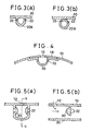
- the drainage channel 20 may be, for instance, a drainage groove 20A having a U-shaped cross section (as shown in Fig. 3(a)), or a drainage tube 20B having a circular cross section (as shown in Fig. 3(b)).
- a drainage groove 20A having a U-shaped cross section (as shown in Fig. 3(a)), or a drainage tube 20B having a circular cross section (as shown in Fig. 3(b)).
- strength of the cap body 10 around the air holes 12 can be increased.
- the drainage tube 20B as shown in Fig. 3(b) is employed, by using, instead of the same material as that for the cap body 10, other materials such as polyvinylchloride, polyethylene terephthalate, and other flexible and light weight synthetic resins, natural rubber, synthetic rubber or the like, the drainage channel 20 can be manufactured as a separate body from the cap body 10. Furthermore, in this case, it is possible to provide the air holes 12 in and attach the drainage tube 20B to a normal type of safety cap in which no measures are taken for ventilation or against rain water, later.
- the drainage tube 20B is attached to the inner wall of the cap body 10, if necessary by using a fitting tool or the like not shown in the figure.
- the drainage tube 20B may be detachably attached thereto.
- a plurality of vent holes 22 are formed in a side wall of the drainage groove 20A or in an upper section of the drainage tube 20B. Location of the vent holes 22 is arranged so that at the draining direction the vent holes 22 would not overlap the air holes 12 for the purpose to prevent rain water entering the air holes 12 from coming inside of the cap body 10 through the vent holes 22.
- vent holes 22 Size and shape of the vent holes 22 are the same as those of the air holes 12.
- An edge of the drainage channel 20 opens to the outside of the cap body 10 as a drainage hole 24.
- the drainage hole 24 having substantially the same size as that of the air hole 12 opens on the outer wall of the cap body 10 at a central portion in the front-to-rear direction thereof.
- the drainage channel 20 may extend as it is with the drainage hole 24 provided as an edge of the drainage groove 20A or the drainage tube 20B in tangent inner peripheral section of the cap body 10.
- the inside and outside of the cap body 10 communicate with each other through the air holes 12, the drainage channel 20, and the vent holes 22, so that external air can freely come into or go out from inside of the cap body 10.
- the drainage channel 20 not only drains rain water, but also functions as a flow path for air.
- the drainage channel 20 also functions as a protection plate, thus the matter being prevented from directly entering inside of the cap body 10.
- Fig. 4 is a partial side view showing a cross section of the drainage channel 20 cut with a plain perpendicular to the drainage direction.
- the cap body 10 is divided in two structural members, which are integrated with each other easily by supersonic welding or some other appropriate means.
- the drainage channel is formed on the outer surface of the cap body 10 and covered with a cover body 18.
- a plurality of air holes 12 is formed at positions opposite to the drainage channel 20 for the same purpose as that described in the above embodiment. As described above, it is preferable to provide the air holes 12 and the vent holes 22 so that both holes do not overlap at the location of the drainage direction.
- the safety cap according to the present invention When the safety cap according to the present invention is used for a rider of an automatic two-wheeled vehicle, it is necessary to take strict measures for waterproofness in rainy weather. These measures are required because rain water in the drainage channel 20 enters the interior of the cap body 10 through the vent holes 22 with high-speed generated during driving the two-wheeled vehicle. It is necessary for waterproofness that the air holes 12, drainage holes 24 and the drainage channel 20 are located at the most suited positions.
- Fig. 5(a) is a partial vertical cross section of the drainage channel 20 according to another embodiment of the present invention
- Fig. 5(b) is a side view taken along the line b-b in Fig. 5(a).
- a windshield plate 30 is provided in front of the vent holes 22 (in the upstream side from the airflow) so that the high speed airflow goes along the outer side of the plates. As a result, the rain water accompanied by the high-speed airflow is prevented from flowing through the vent hole 22.
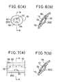
- Fig. 6(a) and Fig. 7(a) are partial side views of cover bodies 18 being seen from the side of a cap body
- Fig. 6(b) and Fig. 7(b) are side views taken along the line b-b in Fig. 6(a) and Fig. 7(a) respectively.
- the same reference numeral are assigned to the same components as those in Fig. 4, and description thereof is omitted herein.
- the cover body 18 is attached to the cap body 10 so that the cover body 18 covers a recessed portion 20C formed in an outer surface of the cap body 10.
- a shape of the recessed portion 20C is like a dish in Fig. 6, and its shape viewed from the front side is circular.
- a circular groove is formed in the outer surface of the cap body 10.
- the number may be in a range from several to tens, and when the recessed portion 20C is provided as the groove as shown in Fig. 7, one or two grooves are enough to fulfill the,purpose. Accordingly, the form and number of cover bodies 18 changes according to the recessed portion 20C.
- the cover bodies 18 may be joined to or engaged with the safety cap according to the necessity.
- the air hole 12 and the drainage hole 24 provided in the cover body 18 may be arranged discretely or as a hole functioning as the two types of hole described above. As the position of drainage hole 24 is lower than that of the air holes 12, when the air hole 12 and drainage hole 24 are provided discretely, as warm air inside the cap body 10 is discharged through the air hole 12 the permeability becomes higher. On the other hand, when one hole functioning as both the air hole 12 and drainage hole 24, a safety cap excellent in waterproofness can be obtained, because there are no air holes 12 in an upper section thereof.
- the safety cap according to the present invention is lightweight and excellent in the permeability and waterproofness in rainy weather or the like. Also, it is safe as a protective cap because of its high strength structure.
- the safety cap according to the present invention can be used in various construction works, in operating a heavy construction machine, in driving a vehicle or an airplane, in guarding works inside or outside a building, in works by policemen or firemen, and further in playing American football, ice hockey, and other types of sports.
- the safety cap can be worn at a site of construction works for a building, a dam, or the like, at a site for construction of a road, tunnel, or the like, or at a work shop in a ship mill, an iron foundry, an ironworks, at a mining site, and at various working sites or plants.
Landscapes
- Helmets And Other Head Coverings (AREA)
- Arrangement Of Elements, Cooling, Sealing, Or The Like Of Lighting Devices (AREA)
- Closures For Containers (AREA)
Abstract
Description
The safety cap according to the present invention comprises a plurality of air holes each penetrating the inner and outer wall of a cap body;
at least one drainage channel provided along the inner wall of the cap body situated opposite to the air holes for discharging water coming into the inside of the cap body through the plurality of air holes from outside of the cap body;
at least one drainage hole situated at the edge of the drainage channel for draining water from the drainage channel; and
a plurality of vent holes in an upper portion of a cross section of the drainage channel perpendicular to the drainage direction.
Claims (8)
- A safety cap comprising:a plurality of air holes (12) each penetrating the inner and outer wall of a cap body (10);at least one drainage channel (20; 20A; 20B) provided along the inner wall of the cap body (10) situated opposite to the air holes (12) for discharging water coming into the inside of the cap body (10) through the plurality of air holes (12) from outside of the cap body (10);at least one drainage hole (24) situated at the edge of the drainage channel (20) for draining water from the drainage channel (20); anda plurality of vent holes (22) in an upper portion of a cross section of the drainage channel (20) perpendicular to the drainage direction.
- A safety cap according to Claim 1; wherein the drainage hole (24) of the drainage channel (20) is opened towards an outer surface of the cap body (10).
- A safety cap according to Claim 1; wherein the drainage channel (20A) has a U-shaped cross section.
- A safety cap comprising:at least one drainage channel (20, 20C) formed in the outer surface of a cap body (10) and having a plurality of vent holes (22) formed in the side walls thereof; wherein the drainage channel (20) is covered with a cover body (18) having at least one air hole (12) and the drainage channel (20) is opened to the outside of the cap body (10) at a section at the lower edge of the drainage channel (20) to form a drainage hole (24).
- A safety cap according to Claim 4; wherein the vent holes (22) in the side walls and the at least one air hole (12) in the cover body (18) are provided so that the holes do not overlap at the location of the drainage direction.
- A safety cap according to Claim 4; wherein the drainage channel (20C) is formed as a recessed portion (20C) on a surface of the cap body (10); wherein the recessed portion (20C) has in its cross-section a dish-shaped form and a shape of the recessed portion (20C) when viewed from the front side is substantially circular; and wherein the recessed portion (20C) has vent holes (22) each provided therein and penetrating the inner and outer walls thereof, and the recessed portion (20C) is covered with a cover body (18) having one air hole (12) and one drainage hole (24) provided at positions where the holes (12, 24) do not overlap the vent holes (22).
- A safety cap according to Claim 6; wherein the air hole (12) and the drainage hole (24) comprise one hole functioning as both of air hole (12) and drainage hole (24).
- A safety cap according to Claim 4; wherein the drainage channel is formed as a peripheral channel on a surface of the cap body (10).
Applications Claiming Priority (3)
| Application Number | Priority Date | Filing Date | Title |
|---|---|---|---|
| JP33505996 | 1996-11-30 | ||
| JP33505996 | 1996-11-30 | ||
| PCT/JP1997/004303 WO1998023176A1 (en) | 1996-11-30 | 1997-11-26 | Safety cap |
Publications (3)
| Publication Number | Publication Date |
|---|---|
| EP0943249A1 EP0943249A1 (en) | 1999-09-22 |
| EP0943249A4 EP0943249A4 (en) | 2001-08-29 |
| EP0943249B1 true EP0943249B1 (en) | 2004-11-10 |
Family
ID=18284302
Family Applications (1)
| Application Number | Title | Priority Date | Filing Date |
|---|---|---|---|
| EP97946794A Expired - Lifetime EP0943249B1 (en) | 1996-11-30 | 1997-11-26 | Safety cap |
Country Status (6)
| Country | Link |
|---|---|
| US (1) | US6151718A (en) |
| EP (1) | EP0943249B1 (en) |
| JP (1) | JP3542139B2 (en) |
| AU (1) | AU5191598A (en) |
| DE (1) | DE69731546T2 (en) |
| WO (1) | WO1998023176A1 (en) |
Families Citing this family (12)
| Publication number | Priority date | Publication date | Assignee | Title |
|---|---|---|---|---|
| US20020178487A1 (en) * | 2001-06-01 | 2002-12-05 | Shiuh-You Lin | Safety helmet with ventilation holes |
| US20060031978A1 (en) * | 2004-08-10 | 2006-02-16 | Pierce Brendan E | Ventilated helmet system |
| US7975320B2 (en) * | 2005-12-20 | 2011-07-12 | Smith Optics, Inc. | Helmet including vent and actuator assembly for moving vent shutter and methods of using same |
| USD571048S1 (en) * | 2007-03-15 | 2008-06-10 | Fowler David B | Rigid protective helmet |
| USD569555S1 (en) * | 2007-03-15 | 2008-05-20 | Fowler David B | Rigid protective helmet |
| US8117676B1 (en) | 2008-12-01 | 2012-02-21 | Jefferson Cardoso | Hardhat with vent strip and lighting configuration |
| USD607629S1 (en) | 2009-05-04 | 2010-01-12 | Dolawat Puangprasert | Ventilated hat |
| US11766085B2 (en) * | 2011-02-09 | 2023-09-26 | 6D Helmets, Llc | Omnidirectional energy management systems and methods |
| CA3097496C (en) | 2018-04-27 | 2023-09-19 | Trafton D. RODGERS | Baseball cap |
| CN109757815A (en) * | 2018-12-20 | 2019-05-17 | 西安铂力特增材技术股份有限公司 | A breathable helmet shell |
| EP4193862A1 (en) * | 2021-12-13 | 2023-06-14 | Optrel Holding AG | Protection device |
| KR102754113B1 (en) * | 2023-08-25 | 2025-01-14 | (주)에이치제이씨 | Helmet with gasket |
Family Cites Families (13)
| Publication number | Priority date | Publication date | Assignee | Title |
|---|---|---|---|---|
| US1170052A (en) * | 1912-04-08 | 1916-02-01 | Magdalena Diener | Ventilated hat. |
| US1991829A (en) * | 1933-09-06 | 1935-02-19 | Texas Harvest Hat Company Inc | Straw helmet hat |
| US3026522A (en) * | 1958-07-02 | 1962-03-27 | Julio Carl J Di | Diving helmet |
| JPS4220108Y1 (en) * | 1965-06-19 | 1967-11-22 | ||
| FR2487645A1 (en) * | 1980-07-30 | 1982-02-05 | Bibollet Jean Claude | Ventilated protective safety helmet - has small hollows in outer surface with ventilation holes along axis of symmetry |
| DE8426051U1 (en) * | 1984-09-04 | 1985-01-31 | Hauptverband der gewerblichen Berufsgenossenschaften e.V., 5300 Bonn | Naturally ventilated safety helmet |
| DE8517547U1 (en) * | 1985-06-15 | 1985-08-01 | Römer GmbH & Co, 7910 Neu-Ulm | Hard hat |
| JPS63162824U (en) * | 1987-04-08 | 1988-10-24 | ||
| DE9212247U1 (en) * | 1992-09-11 | 1993-04-08 | F. M. Fallert Motor GmbH & Co, Motorrad-Sport KG, 7590 Achern | Crash helmet with anatomically shaped padding and device for its manufacture |
| US5533500A (en) * | 1992-03-04 | 1996-07-09 | Her-Mou; Lin | Helmet with an air filtering device |
| JPH08209431A (en) * | 1995-01-30 | 1996-08-13 | Shiiraizu Corp:Kk | Protective cap |
| CN1130997C (en) * | 1995-08-11 | 2003-12-17 | 喜来滋有限公司 | Protective cap |
| US5819318A (en) * | 1997-10-16 | 1998-10-13 | Steven Tse | Head covering with adjustable sunshade visor and inside ventilation |
-
1997
- 1997-11-26 WO PCT/JP1997/004303 patent/WO1998023176A1/en not_active Ceased
- 1997-11-26 DE DE69731546T patent/DE69731546T2/en not_active Expired - Lifetime
- 1997-11-26 EP EP97946794A patent/EP0943249B1/en not_active Expired - Lifetime
- 1997-11-26 AU AU51915/98A patent/AU5191598A/en not_active Abandoned
- 1997-11-26 US US09/308,886 patent/US6151718A/en not_active Expired - Fee Related
- 1997-11-26 JP JP52451598A patent/JP3542139B2/en not_active Expired - Lifetime
Also Published As
| Publication number | Publication date |
|---|---|
| US6151718A (en) | 2000-11-28 |
| DE69731546D1 (en) | 2004-12-16 |
| DE69731546T2 (en) | 2005-10-27 |
| AU5191598A (en) | 1998-06-22 |
| EP0943249A4 (en) | 2001-08-29 |
| JP3542139B2 (en) | 2004-07-14 |
| WO1998023176A1 (en) | 1998-06-04 |
| EP0943249A1 (en) | 1999-09-22 |
Similar Documents
| Publication | Publication Date | Title |
|---|---|---|
| EP0890320B1 (en) | Protective cap | |
| JPWO1997006706A1 (en) | hard hat | |
| US6151718A (en) | Safety cap | |
| US11844390B2 (en) | Helmet with shock absorbing inserts | |
| US5734994A (en) | Ventilated safety helmet with progressively crushable liner | |
| CN102370285B (en) | Improved sports safety helmet | |
| JPWO1998023176A1 (en) | hard hat | |
| WO2005006901A1 (en) | Protective cap | |
| JP2000303246A (en) | Protective hat | |
| KR19990025308A (en) | Versatile safety hat and helmet with inflated air hat | |
| JPH08209431A (en) | Protective cap | |
| KR200489509Y1 (en) | Functional Safety Helmet | |
| JP2021147732A (en) | Helmet | |
| WO1995028101A1 (en) | Safety cap | |
| EP4451990B1 (en) | Helmet | |
| KR200187556Y1 (en) | Ventilative safety helmet | |
| KR200320556Y1 (en) | Safety Helmet | |
| US20260108006A1 (en) | Helmet | |
| KR20020061454A (en) | Full face type helmet | |
| JPH07278935A (en) | Protective cap | |
| JPH01156506A (en) | Hat for traffic safety | |
| AU2005202254A1 (en) | Safety head gear | |
| KR20010075831A (en) | Ventilative safety helmet | |
| WO2002009545A1 (en) | Safety hat | |
| IT202000004330U1 (en) | PROTECTION FOR VEHICLES AND PEOPLE APPLICABLE TO TREES ON THE ROADSIDE |
Legal Events
| Date | Code | Title | Description |
|---|---|---|---|
| PUAI | Public reference made under article 153(3) epc to a published international application that has entered the european phase |
Free format text: ORIGINAL CODE: 0009012 |
|
| 17P | Request for examination filed |
Effective date: 19990601 |
|
| AK | Designated contracting states |
Kind code of ref document: A1 Designated state(s): DE FR GB IT |
|
| A4 | Supplementary search report drawn up and despatched |
Effective date: 20010716 |
|
| AK | Designated contracting states |
Kind code of ref document: A4 Designated state(s): DE FR GB IT |
|
| 17Q | First examination report despatched |
Effective date: 20030521 |
|
| GRAP | Despatch of communication of intention to grant a patent |
Free format text: ORIGINAL CODE: EPIDOSNIGR1 |
|
| RAP1 | Party data changed (applicant data changed or rights of an application transferred) |
Owner name: BUILMATEL CO. LTD. |
|
| GRAS | Grant fee paid |
Free format text: ORIGINAL CODE: EPIDOSNIGR3 |
|
| GRAA | (expected) grant |
Free format text: ORIGINAL CODE: 0009210 |
|
| AK | Designated contracting states |
Kind code of ref document: B1 Designated state(s): DE FR GB IT |
|
| REG | Reference to a national code |
Ref country code: GB Ref legal event code: FG4D |
|
| REF | Corresponds to: |
Ref document number: 69731546 Country of ref document: DE Date of ref document: 20041216 Kind code of ref document: P |
|
| ET | Fr: translation filed | ||
| PLBE | No opposition filed within time limit |
Free format text: ORIGINAL CODE: 0009261 |
|
| STAA | Information on the status of an ep patent application or granted ep patent |
Free format text: STATUS: NO OPPOSITION FILED WITHIN TIME LIMIT |
|
| 26N | No opposition filed |
Effective date: 20050811 |
|
| PGFP | Annual fee paid to national office [announced via postgrant information from national office to epo] |
Ref country code: IT Payment date: 20081127 Year of fee payment: 12 |
|
| PGFP | Annual fee paid to national office [announced via postgrant information from national office to epo] |
Ref country code: FR Payment date: 20081118 Year of fee payment: 12 |
|
| PGFP | Annual fee paid to national office [announced via postgrant information from national office to epo] |
Ref country code: GB Payment date: 20081125 Year of fee payment: 12 |
|
| PGFP | Annual fee paid to national office [announced via postgrant information from national office to epo] |
Ref country code: DE Payment date: 20091113 Year of fee payment: 13 |
|
| GBPC | Gb: european patent ceased through non-payment of renewal fee |
Effective date: 20091126 |
|
| REG | Reference to a national code |
Ref country code: FR Ref legal event code: ST Effective date: 20100730 |
|
| PG25 | Lapsed in a contracting state [announced via postgrant information from national office to epo] |
Ref country code: FR Free format text: LAPSE BECAUSE OF NON-PAYMENT OF DUE FEES Effective date: 20091130 |
|
| PG25 | Lapsed in a contracting state [announced via postgrant information from national office to epo] |
Ref country code: GB Free format text: LAPSE BECAUSE OF NON-PAYMENT OF DUE FEES Effective date: 20091126 |
|
| PG25 | Lapsed in a contracting state [announced via postgrant information from national office to epo] |
Ref country code: IT Free format text: LAPSE BECAUSE OF NON-PAYMENT OF DUE FEES Effective date: 20091126 |
|
| REG | Reference to a national code |
Ref country code: DE Ref legal event code: R119 Ref document number: 69731546 Country of ref document: DE Effective date: 20110601 Ref country code: DE Ref legal event code: R119 Ref document number: 69731546 Country of ref document: DE Effective date: 20110531 |
|
| PG25 | Lapsed in a contracting state [announced via postgrant information from national office to epo] |
Ref country code: DE Free format text: LAPSE BECAUSE OF NON-PAYMENT OF DUE FEES Effective date: 20110531 |