EP0942604B1 - Verfahren und Vorrichtung zur Erzeugung eines begrenzenden Rechtecks einer Videoobjektfläche für zwischenzeilenabgetastete Videosignale - Google Patents
Verfahren und Vorrichtung zur Erzeugung eines begrenzenden Rechtecks einer Videoobjektfläche für zwischenzeilenabgetastete Videosignale Download PDFInfo
- Publication number
- EP0942604B1 EP0942604B1 EP99104623A EP99104623A EP0942604B1 EP 0942604 B1 EP0942604 B1 EP 0942604B1 EP 99104623 A EP99104623 A EP 99104623A EP 99104623 A EP99104623 A EP 99104623A EP 0942604 B1 EP0942604 B1 EP 0942604B1
- Authority
- EP
- European Patent Office
- Prior art keywords
- bounding rectangle
- coordinate
- reference point
- spatial reference
- coordinate value
- Prior art date
- Legal status (The legal status is an assumption and is not a legal conclusion. Google has not performed a legal analysis and makes no representation as to the accuracy of the status listed.)
- Expired - Lifetime
Links
Images





Classifications
-
- H—ELECTRICITY
- H04—ELECTRIC COMMUNICATION TECHNIQUE
- H04N—PICTORIAL COMMUNICATION, e.g. TELEVISION
- H04N19/00—Methods or arrangements for coding, decoding, compressing or decompressing digital video signals
- H04N19/10—Methods or arrangements for coding, decoding, compressing or decompressing digital video signals using adaptive coding
- H04N19/102—Methods or arrangements for coding, decoding, compressing or decompressing digital video signals using adaptive coding characterised by the element, parameter or selection affected or controlled by the adaptive coding
- H04N19/119—Adaptive subdivision aspects, e.g. subdivision of a picture into rectangular or non-rectangular coding blocks
Definitions
- the present invention relates to a video signal encoding method and apparatus, and more particularly to a method and apparatus for generating a bounding rectangle of a video object plane (VOP) for interlaced scan type video signals.
- VOP video object plane
- Video encoding schemes are classified into a frame-based encoding scheme in which pixels existing in the entire region of a rectangular frame are encoded, and an object-based encoding scheme in which only arbitrary shaped regions of a rectangular frame are encoded.
- the frame-based encoding scheme there are H.261 and H.263, which are video coding standards recommended by International Telecommunication Union - Telecommunication Standardization Sector (ITU-T), and MPEG-1 and MPEG-2 standardized by Moving Picture Experts Group (MPEG) of International Standardization Organization/International Electrotechnical Commission Joint Technical Committee 1/Sub Committee 29/Working Group 11 (ISO/IEC JTC1/SC29/WG11).
- MPEG Moving Picture Experts Group
- ISO/IEC JTC1/SC29/WG11 International Electrotechnical Commission Joint Technical Committee 1/Sub Committee 29/Working Group 11
- MPEG-4 standardized by MPEG of ISO/IEC JTC1/SC29/WG11.
- an input video is divided into a plurality of video object planes (VOPs) and processed on the basis of VOP.
- VOPs video object planes
- Each VOP is defined by a bounding rectangle surrounding an arbitrarily shaped object.
- video encoding according to the object-based encoding scheme involves the steps of: extracting luminance shape information from an input video signal and forming VOPs using extracted luminance shape information; and encoding video information of every VOP.
- the step of encoding video information of every VOP consists of 3 substeps.
- the 1st substep is encoding shape information of every VOP, based on the extracted luminance shape information.
- the 2nd substep is subsampling the extracted luminance shape information, thereby extracting chrominance shape information from the extracted luminance shape information, padding a chrominance signal, based on the extracted chrominance shape information, and encoding chrominance of every VOP.
- the 3rd substep is padding a luminance signal, based on the extracted luminance shape information, and encoding luminance of every VOP.
- a conservative chrominance shape subsampling method has conventionally been used as the subsampling method for extracting chrominance shape information from the extracted luminance shape information.
- This method is a subsampling method in which chrominance shape information is extracted using four adjacent luminance shape informations defining a rectangle.
- An example of such a conservative chrominance shape subsampling method is disclosed in Europe Patent No. EP806871 issued to Dae Woo Electronics Co., Ltd. (titled: METHOD AND APPARATUS FOR GENERATING CHROMINANCE SHAPE INFORMATION OF A VIDEO OBJECT PLANE IN A VIDEO SIGNAL).
- input video signals for coding and subsampling may be frame type video signals according to a progressive scan scheme in which all signals of one frame of video are simultaneously acquired while being scanned within the same period of time, as shown in Fig. 1a, or may be field type video signals according to an interlaced scan scheme in which signals of one frame of video are sorted into those of a top field and those of a bottom field which are different from each other in terms of the video signal acquisition time, as shown in Fig. 1b.
- a field-based chrominance shape subsampling method which is a subsampling method for interlaced scan type video signals and disclosed in the pending Korean Patent Application No. 98-7374 filed on March 5, 1998 by the applicant.
- This method is a subsampling method in which chrominance shape information is extracted, based on four adjacent luminance shape informations existing in the same field and defining a rectangle.
- chrominance shape information i existing in the bottom field is extracted based on luminance shape information c, d, g, and h existing in the top field while chrominance shape information existing in the top field is extracted based on luminance shape information existing in the bottom field, if bounding rectangles defining a subsampling range of chrominance shape information are erroneously set.
- an object of the invention is to provide a method and apparatus for generating a bounding rectangle of a VOP for interlaced scan type video signals, which method and apparatus are capable of accurately generating a bounding rectangle, thereby preventing a color bleeding from occurring in the field-based chrominance shape subsampling.
- the video encoder includes a VOP formation unit 100 for deriving luminance shape information from an input video signal, and dividing the input video signal into VOPs respectively corresponding to objects existing in the input video signal, a plurality of VOP encoding unit 200 for receiving output signals, associated with respective VOPs, from the VOP formation unit 100, respectively, and encoding the received signals, respectively, and a multiplexer (MUX) unit 300 for multiplexing output signals from the VOP encoding unit 200, thereby outputting a bitstream.
- VOP formation unit 100 for deriving luminance shape information from an input video signal, and dividing the input video signal into VOPs respectively corresponding to objects existing in the input video signal
- a plurality of VOP encoding unit 200 for receiving output signals, associated with respective VOPs, from the VOP formation unit 100, respectively, and encoding the received signals, respectively
- MUX multiplexer
- VOP formation unit 100 which is applicable to the video encoder and configured in accordance with the present invention, is illustrated.
- the VOP formation unit 100 includes an object extraction unit 101, a bounding rectangle formation unit 102, an optimum setting determination unit 103, and a bounding rectangle adjustment unit 104.
- the object extraction unit 101 is a section for extracting luminance shape information from an input video signal by applying a segmentation method to the input video signal.
- the bounding rectangle formation unit 102 is a section for forming a bounding rectangle of a VOP in such a fashion that the bounding rectangle contains an object therein, based on the extracted luminance shape information received from the object extraction unit 100. It is preferred that the bounding rectangle formation unit 102 be configured to form the tightest rectangle, namely, a rectangle having the smallest area while containing an object therein, as the bounding rectangle, in order to achieve an enhancement in processing efficiency.
- the spatial reference point means a point where luminance shape information existing on the left-top portion of the interior of the bounding rectangle is positioned. This point is a reference point for the setting of the bounding rectangle.
- the bounding rectangle adjustment unit 104 is a section for varying the bounding rectangle when the spatial reference point of the bounding rectangle is not positioned on the x-y coordinate of coordinate value (2m, 4n), thereby allowing the spatial reference point of the bounding rectangle to be positioned on the x-y coordinate of coordinate value (2m, 4n).
- the bounding rectangle adjustment unit 104 be configured to vary the bounding rectangle, when the spatial reference point of the bounding rectangle is not positioned on the x-y coordinate of coordinate value (2m, 4n), in such a fashion that the spatial reference point of the bounding rectangle is positioned on an x-y coordinate of the coordinate value (2m, 4n) minimizing the interior area of the bounding rectangle.
- the bounding rectangle formation unit 102, the optimum setting determination unit 103, and the bounding rectangle adjustment unit compose an apparatus for generating a bounding rectangle of a VOP for interlaced scan type video signals.
- an apparatus for generating a bounding rectangle of a VOP for interlaced scan type video signals will be referred to as an apparatus for generating a bounding rectangle of a VOP for interlaced scan type video signals.
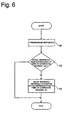
- a bounding rectangle formation step S1 is first executed in the bounding rectangle forming unit 102.
- the bounding rectangle forming unit 102 sets a bounding rectangle, in such a fashion that the bounding rectangle contains an object therein, based on the extracted luminance shape information received from the object extraction unit 100.
- the bounding rectangle formation step S1 is executed to form the tightest rectangle as the bounding rectangle in order to achieve an enhancement in processing efficiency.
- an optimum setting determination step S2 is executed in the optimum setting determination unit 103.
- a bounding rectangle adjustment step S3 is executed in the bounding rectangle adjustment unit 104 when it is determined at the optimum setting determination step S2 that the spatial reference point of the bounding rectangle is not positioned on the x-y coordinate of coordinate value (2m, 4n).
- the bounding rectangle adjustment unit 104 varies the bounding rectangle in such a fashion that the spatial reference point of the bounding rectangle is positioned on the x-y coordinate of coordinate value (2m, 4n).
- the bounding rectangle adjustment step S3 is preferably executed to vary the bounding rectangle, when the spatial reference point of the bounding rectangle is not positioned on the x-y coordinate of coordinate value (2m, 4n), in such a fashion that the spatial reference point of the bounding rectangle is positioned on an x-y coordinate of the coordinate value (2m, 4n) minimizing the interior area of the bounding rectangle.
- the present invention provides a method and apparatus for generating a bounding rectangle of a VOP for interlaced scan type video signals, which are capable of accurately generating a bounding rectangle, thereby preventing a color bleeding from occurring in the field-based chrominance shape subsampling.
- a VOP is defined based on a bounding rectangle appropriately set in accordance with the present invention
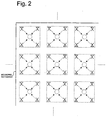
- extraction of chrominance shape information may be correctly carried out in such a fashion that, as shown in Fig.
- chrominance shape information i existing in the bottom field is extracted based on luminance shape information a, b, e, and f existing in the bottom field whereas chrominance shape information existing in the top field is extracted based on luminance shape information existing in the top field. Accordingly, it is possible to completely solve the color bleeding problem.
Landscapes
- Engineering & Computer Science (AREA)
- Multimedia (AREA)
- Signal Processing (AREA)
- Television Systems (AREA)
- Compression Or Coding Systems Of Tv Signals (AREA)
- Processing Of Color Television Signals (AREA)
Claims (6)
- Verfahren zum Erzeugen eines graphischen Begrenzungsrechtecks einer Videoobjektebene für Videosignale von Typ einer verschachtelten Abtastung, mit:einem das graphische Begrenzungsrecheck ausbildenden Schritt zur Herstellung eines graphischen Begrenzungsrechtecks einer Videoobjektebene in einer solchen Weise, daß das graphische Begrenzungsrechteck ein Objekt enthält basierend auf Eingangsluminanzgestaltinformationen;einem die optimale Einstellung bestimmenden Schritt zur Bestimmung, ob ein räumlicher Bezugspunkt des graphischen Begrenzungsrechtecks auf einer x-y-Koordinate des Koordinatenwertes (2m, 4n) (m und n = 0, 1, 2, 3, 4, ....) positioniert ist; undeinen das graphische Begrenzungsrechteck einstellenden Schritt, bei dem das graphische Begrenzungsrechteck variiert wird, wenn bei dem die optimale Einstellung bestimmenden Schritt festgelegt wurde, daß der räumliche Bezugspunkt des graphischen Begrenzungsrechtecks nicht auf der x-y-Koordinate des Koordinatenwertes (2m, 4n) positioniert ist, in einer solchen Weise, daß der räumliche Bezugspunkt des graphischen Begrenzungsrechtecks auf der x-y-Koordinate des Koordinatenwertes (2m, 4n) positioniert wird.
- Verfahren nach Anspruch 1, bei dem der das graphische Begrenzungsrechteck einstellende Schritt derart ausgeführt wird, um das graphische Begrenzungsrechteck zu variieren, wenn der räumliche Bezugspunkt des graphischen Begrenzungsrechtecks nicht auf der x-y-Koordinate des Koordinatenwertes (2m, 4n) positioniert ist, in einer solchen Weise, daß der räumliche Bezugspunkt des graphischen Begrenzungsrechtecks auf einer x-y-Koordinate des Koordinatenwertes (2m, 4n) positioniert wird und zwar unter Minimierung der inneren Fläche des graphischen Begrenzungsrechtecks.
- Verfahren nach Anspruch 1, bei dem der das graphische Begrenzungsrechteck ausbildende Schritt so durchgeführt wird, um das dichteste (tightest) Rechteck als graphisches Begrenzungsrechteck zu bilden; und
der das graphische Begrenzungsrechteck einstellende Schritt so ausgeführt wird, um das graphische Begrenzungsrechteck zu variieren, wenn der räumliche Bezugspunkt des graphischen Begrenzungsrechtecks nicht auf der x-y-Koordinate des Koordinatenwertes (2m, 4n) positioniert ist, in einer solchen Weise, daß der räumliche Bezugspunkt des graphischen Begrenzungsrechtecks auf einer x-y-Koordinate des Koordinatenwertes (2m, 4n) positioniert wird und zwar unter Minimierung der inneren Fläche des graphischen Begrenzungsrechtecks. - Gerät zum Erzeugen eines graphischen Begrenzungsrechtecks einer Videoobjektebene für Videosignale vom verschachtelten Abtasttyp, mit:einer Bildungseinheit (102) für das graphische Begrenzungsrechteck, um ein graphisches Begrenzungsrechteck einer Videoobjektebene in einer solchen Weise zu bilden, daß das graphische Begrenzungsrechteck darin ein Objekt enthält und zwar basierend auf Eingabe-Luminanzgestaltinformationen;eine die optimale Einstellung bestimmende Einheit (103), um festzulegen, ob ein räumlicher Bezugspunkt des graphischen Begrenzungsrechtecks auf einer x-y-Koordinate des Koordinatenwertes (2m, 4n) (m und n = 0, 1, 2, 3, 4,...)positioniert ist oder nicht; undeine Einstelleinheit (104) für das graphische Begrenzungsrechteck zum Variieren des graphischen Begrenzungsrechtecks, wenn der räumliche Bezugspunkt des graphischen Begrenzungsrechtecks nicht auf der x-y-Koordinate des Koordinatenwertes (2m, 4n) positioniert ist, in einer solchen Weise, daß der räumliche Bezugspunkt des graphischen Begrenzungsrechtecks auf der x-y-Koordinate des Koordinatenwertes (2m, 4n) positioniert wird.
- Gerät nach Anspruch 4, bei dem die Einstelleinheit für das graphische Begrenzungsrechteck das graphische Begrenzungsrechteck variiert, wenn der räumliche Bezugspunkt des graphischen Begrenzungsrechtecks nicht auf der x-y-Koordinate des Koordinatenwertes (2m, 4n) positioniert ist, in einer solchen Weise, daß der räumliche Bezugspunkt des graphischen Begrenzungsrechtecks auf einer x-y-Koordinate des Koordinatenwertes (2m, 4n) unter Minimierung der inneren Fläche des graphischen Begrenzungsrechtecks positioniert wird.
- Gerät nach Anspruch 4, bei dem:die Bildungseinheit für das graphische Begrenzungsrechteck das engste (tightest) Rechteck des graphisches Begrenzungsrechtecks ausbildet; unddie Einstelleinheit für das graphische Begrenzungsrechteck das graphische Begrenzungsrechteck variiert, wenn der räumliche Bezugspunkt des graphischen Begrenzungsrechtecks nicht auf der x-y-Koordinate des Koordinatenwertes (2m, 4n) positioniert ist, in einer solchen Weise, daß der räumliche Bezugspunkt des graphischen Begrenzungsrechtecks auf einer x-y-Koordinate des Koordinatenwertes (2m, 4n) unter Minimierung der inneren Fläche des graphischen Begrenzungsrechtecks positioniert wird.
Applications Claiming Priority (4)
| Application Number | Priority Date | Filing Date | Title |
|---|---|---|---|
| KR9807977 | 1998-03-10 | ||
| KR19980007977 | 1998-03-10 | ||
| KR9904675 | 1999-02-10 | ||
| KR1019990004675A KR100335629B1 (ko) | 1998-03-10 | 1999-02-10 | 비월주사방식 영상신호에 대한 vop 경계 사각형 설정방법 및장치 |
Publications (3)
| Publication Number | Publication Date |
|---|---|
| EP0942604A2 EP0942604A2 (de) | 1999-09-15 |
| EP0942604A3 EP0942604A3 (de) | 2001-03-07 |
| EP0942604B1 true EP0942604B1 (de) | 2002-06-12 |
Family
ID=26633507
Family Applications (1)
| Application Number | Title | Priority Date | Filing Date |
|---|---|---|---|
| EP99104623A Expired - Lifetime EP0942604B1 (de) | 1998-03-10 | 1999-03-09 | Verfahren und Vorrichtung zur Erzeugung eines begrenzenden Rechtecks einer Videoobjektfläche für zwischenzeilenabgetastete Videosignale |
Country Status (5)
| Country | Link |
|---|---|
| US (1) | US6396957B1 (de) |
| EP (1) | EP0942604B1 (de) |
| JP (1) | JP3382173B2 (de) |
| AT (1) | ATE219314T1 (de) |
| DE (1) | DE69901744T2 (de) |
Families Citing this family (1)
| Publication number | Priority date | Publication date | Assignee | Title |
|---|---|---|---|---|
| JP4151158B2 (ja) * | 1999-06-14 | 2008-09-17 | ソニー株式会社 | シーン記述生成装置及び方法 |
Family Cites Families (8)
| Publication number | Priority date | Publication date | Assignee | Title |
|---|---|---|---|---|
| KR100209412B1 (ko) * | 1996-05-10 | 1999-07-15 | 전주범 | 비디오 신호의 유호 색차 성분 부호화 방법 |
| KR100209413B1 (ko) * | 1996-05-23 | 1999-07-15 | 전주범 | 블럭-기반 비디오 신호 부호화 시스템에 이용하기 위한그리드 결정방법 |
| JP3263807B2 (ja) * | 1996-09-09 | 2002-03-11 | ソニー株式会社 | 画像符号化装置および画像符号化方法 |
| JP4034380B2 (ja) * | 1996-10-31 | 2008-01-16 | 株式会社東芝 | 画像符号化/復号化方法及び装置 |
| US5974184A (en) * | 1997-03-07 | 1999-10-26 | General Instrument Corporation | Intra-macroblock DC and AC coefficient prediction for interlaced digital video |
| US6005980A (en) * | 1997-03-07 | 1999-12-21 | General Instrument Corporation | Motion estimation and compensation of video object planes for interlaced digital video |
| KR19980084420A (ko) * | 1997-05-23 | 1998-12-05 | 배순훈 | 윤곽정보 검출장치 및 방법 |
| US6057884A (en) * | 1997-06-05 | 2000-05-02 | General Instrument Corporation | Temporal and spatial scaleable coding for video object planes |
-
1999
- 1999-03-08 JP JP06039599A patent/JP3382173B2/ja not_active Expired - Fee Related
- 1999-03-09 DE DE69901744T patent/DE69901744T2/de not_active Expired - Lifetime
- 1999-03-09 AT AT99104623T patent/ATE219314T1/de not_active IP Right Cessation
- 1999-03-09 EP EP99104623A patent/EP0942604B1/de not_active Expired - Lifetime
- 1999-03-10 US US09/265,799 patent/US6396957B1/en not_active Expired - Lifetime
Also Published As
| Publication number | Publication date |
|---|---|
| ATE219314T1 (de) | 2002-06-15 |
| EP0942604A3 (de) | 2001-03-07 |
| DE69901744D1 (de) | 2002-07-18 |
| JP3382173B2 (ja) | 2003-03-04 |
| US6396957B1 (en) | 2002-05-28 |
| EP0942604A2 (de) | 1999-09-15 |
| DE69901744T2 (de) | 2002-10-24 |
| JPH11331836A (ja) | 1999-11-30 |
Similar Documents
| Publication | Publication Date | Title |
|---|---|---|
| US6122014A (en) | Modified chroma keyed technique for simple shape coding for digital video | |
| US5751378A (en) | Scene change detector for digital video | |
| USRE41383E1 (en) | Method and apparatus for encoding interplaced macroblock texture information | |
| EP0755604B1 (de) | Vorrichtung und methode zum übertragen und empfangen von videosignalen | |
| KR100306070B1 (ko) | 이진형상신호부호화장치및방법 | |
| US6546142B2 (en) | Motion image coding apparatus for performing hierarchical coding | |
| EP0806871B1 (de) | Verfahren und Vorrichtung zur Erzeugung Chrominanzkonturinformation einer Videoobjektebene eines Videosignals | |
| US6069976A (en) | Apparatus and method for adaptively coding an image signal | |
| US6229930B1 (en) | Image processing apparatus, image processing method, image data structure, and data storage media | |
| US5978031A (en) | Method and apparatus for determining an optimum grid for use in a block-based video signal coding system | |
| EP0942604B1 (de) | Verfahren und Vorrichtung zur Erzeugung eines begrenzenden Rechtecks einer Videoobjektfläche für zwischenzeilenabgetastete Videosignale | |
| US20060140264A1 (en) | Video encoding method and corresponding encoding and decoding devices | |
| KR100335629B1 (ko) | 비월주사방식 영상신호에 대한 vop 경계 사각형 설정방법 및장치 | |
| EP0940995B1 (de) | Verfahren und Gerät für die Herausziehung von Farbkonturinformation aus Videohalbbildern | |
| KR100568531B1 (ko) | 동영상부호화 및 복호화에 있어서의 윤곽선추출방법 | |
| KR100568532B1 (ko) | 동영상부호화 및 복호화에 있어서의 윤곽선충진방법 | |
| HK1010441A (en) | Scene change detector for digital video | |
| KR20000021867A (ko) | 이진 형상 신호의 움직임 벡터 부호화 방법 |
Legal Events
| Date | Code | Title | Description |
|---|---|---|---|
| PUAI | Public reference made under article 153(3) epc to a published international application that has entered the european phase |
Free format text: ORIGINAL CODE: 0009012 |
|
| AK | Designated contracting states |
Kind code of ref document: A2 Designated state(s): AT BE CH CY DE DK ES FI FR GB GR IE IT LI LU MC NL PT SE |
|
| AX | Request for extension of the european patent |
Free format text: AL;LT;LV;MK;RO;SI |
|
| RIN1 | Information on inventor provided before grant (corrected) |
Inventor name: KIM, JONG DEUK Inventor name: KIM, HAE KWANG Inventor name: MOON, JOO HEE Inventor name: PARK, CHEOL SOO |
|
| RIN1 | Information on inventor provided before grant (corrected) |
Inventor name: KIM, JONG DEUK Inventor name: KIM, HAE KWANG Inventor name: MOON, JOO HEE Inventor name: PARK, CHEOL SOO |
|
| PUAL | Search report despatched |
Free format text: ORIGINAL CODE: 0009013 |
|
| AK | Designated contracting states |
Kind code of ref document: A3 Designated state(s): AT BE CH CY DE DK ES FI FR GB GR IE IT LI LU MC NL PT SE |
|
| AX | Request for extension of the european patent |
Free format text: AL;LT;LV;MK;RO;SI |
|
| 17P | Request for examination filed |
Effective date: 20010717 |
|
| RAP1 | Party data changed (applicant data changed or rights of an application transferred) |
Owner name: HYNIX SEMICONDUCTOR INC. |
|
| RAP1 | Party data changed (applicant data changed or rights of an application transferred) |
Owner name: HYUNDAI CURITEL, INC. |
|
| GRAG | Despatch of communication of intention to grant |
Free format text: ORIGINAL CODE: EPIDOS AGRA |
|
| AKX | Designation fees paid |
Free format text: AT BE CH CY DE DK ES FI FR GB GR IE IT LI LU MC NL PT SE |
|
| AXX | Extension fees paid |
Free format text: AL PAYMENT 20010717;LT PAYMENT 20010717;LV PAYMENT 20010717;MK PAYMENT 20010717;RO PAYMENT 20010717;SI PAYMENT 20010717 |
|
| 17Q | First examination report despatched |
Effective date: 20011025 |
|
| GRAG | Despatch of communication of intention to grant |
Free format text: ORIGINAL CODE: EPIDOS AGRA |
|
| GRAH | Despatch of communication of intention to grant a patent |
Free format text: ORIGINAL CODE: EPIDOS IGRA |
|
| GRAH | Despatch of communication of intention to grant a patent |
Free format text: ORIGINAL CODE: EPIDOS IGRA |
|
| GRAA | (expected) grant |
Free format text: ORIGINAL CODE: 0009210 |
|
| AK | Designated contracting states |
Kind code of ref document: B1 Designated state(s): AT BE CH CY DE DK ES FI FR GB GR IE IT LI LU MC NL PT SE |
|
| AX | Request for extension of the european patent |
Free format text: AL PAYMENT 20010717;LT PAYMENT 20010717;LV PAYMENT 20010717;MK PAYMENT 20010717;RO PAYMENT 20010717;SI PAYMENT 20010717 |
|
| LTIE | Lt: invalidation of european patent or patent extension | ||
| PG25 | Lapsed in a contracting state [announced via postgrant information from national office to epo] |
Ref country code: LI Free format text: LAPSE BECAUSE OF FAILURE TO SUBMIT A TRANSLATION OF THE DESCRIPTION OR TO PAY THE FEE WITHIN THE PRESCRIBED TIME-LIMIT Effective date: 20020612 Ref country code: GR Free format text: LAPSE BECAUSE OF FAILURE TO SUBMIT A TRANSLATION OF THE DESCRIPTION OR TO PAY THE FEE WITHIN THE PRESCRIBED TIME-LIMIT Effective date: 20020612 Ref country code: CH Free format text: LAPSE BECAUSE OF FAILURE TO SUBMIT A TRANSLATION OF THE DESCRIPTION OR TO PAY THE FEE WITHIN THE PRESCRIBED TIME-LIMIT Effective date: 20020612 Ref country code: BE Free format text: LAPSE BECAUSE OF FAILURE TO SUBMIT A TRANSLATION OF THE DESCRIPTION OR TO PAY THE FEE WITHIN THE PRESCRIBED TIME-LIMIT Effective date: 20020612 Ref country code: AT Free format text: LAPSE BECAUSE OF FAILURE TO SUBMIT A TRANSLATION OF THE DESCRIPTION OR TO PAY THE FEE WITHIN THE PRESCRIBED TIME-LIMIT Effective date: 20020612 |
|
| REF | Corresponds to: |
Ref document number: 219314 Country of ref document: AT Date of ref document: 20020615 Kind code of ref document: T |
|
| REG | Reference to a national code |
Ref country code: GB Ref legal event code: FG4D |
|
| REG | Reference to a national code |
Ref country code: CH Ref legal event code: EP |
|
| REF | Corresponds to: |
Ref document number: 69901744 Country of ref document: DE Date of ref document: 20020718 |
|
| REG | Reference to a national code |
Ref country code: IE Ref legal event code: FG4D |
|
| PG25 | Lapsed in a contracting state [announced via postgrant information from national office to epo] |
Ref country code: DK Free format text: LAPSE BECAUSE OF FAILURE TO SUBMIT A TRANSLATION OF THE DESCRIPTION OR TO PAY THE FEE WITHIN THE PRESCRIBED TIME-LIMIT Effective date: 20020912 |
|
| PG25 | Lapsed in a contracting state [announced via postgrant information from national office to epo] |
Ref country code: PT Free format text: LAPSE BECAUSE OF FAILURE TO SUBMIT A TRANSLATION OF THE DESCRIPTION OR TO PAY THE FEE WITHIN THE PRESCRIBED TIME-LIMIT Effective date: 20020916 |
|
| ET | Fr: translation filed | ||
| ET1 | Fr: translation filed ** revision of the translation of the patent or the claims | ||
| PG25 | Lapsed in a contracting state [announced via postgrant information from national office to epo] |
Ref country code: ES Free format text: LAPSE BECAUSE OF FAILURE TO SUBMIT A TRANSLATION OF THE DESCRIPTION OR TO PAY THE FEE WITHIN THE PRESCRIBED TIME-LIMIT Effective date: 20021220 |
|
| REG | Reference to a national code |
Ref country code: CH Ref legal event code: PL |
|
| PG25 | Lapsed in a contracting state [announced via postgrant information from national office to epo] |
Ref country code: LU Free format text: LAPSE BECAUSE OF NON-PAYMENT OF DUE FEES Effective date: 20030309 Ref country code: CY Free format text: LAPSE BECAUSE OF FAILURE TO SUBMIT A TRANSLATION OF THE DESCRIPTION OR TO PAY THE FEE WITHIN THE PRESCRIBED TIME-LIMIT Effective date: 20030309 |
|
| PG25 | Lapsed in a contracting state [announced via postgrant information from national office to epo] |
Ref country code: IE Free format text: LAPSE BECAUSE OF NON-PAYMENT OF DUE FEES Effective date: 20030310 |
|
| PG25 | Lapsed in a contracting state [announced via postgrant information from national office to epo] |
Ref country code: MC Free format text: LAPSE BECAUSE OF NON-PAYMENT OF DUE FEES Effective date: 20030331 |
|
| PLBE | No opposition filed within time limit |
Free format text: ORIGINAL CODE: 0009261 |
|
| STAA | Information on the status of an ep patent application or granted ep patent |
Free format text: STATUS: NO OPPOSITION FILED WITHIN TIME LIMIT |
|
| 26N | No opposition filed |
Effective date: 20030313 |
|
| REG | Reference to a national code |
Ref country code: IE Ref legal event code: MM4A |
|
| REG | Reference to a national code |
Ref country code: FR Ref legal event code: PLFP Year of fee payment: 17 |
|
| REG | Reference to a national code |
Ref country code: FR Ref legal event code: PLFP Year of fee payment: 18 |
|
| REG | Reference to a national code |
Ref country code: DE Ref legal event code: R082 Ref document number: 69901744 Country of ref document: DE Representative=s name: KUHNEN & WACKER PATENT- UND RECHTSANWALTSBUERO, DE Ref country code: DE Ref legal event code: R081 Ref document number: 69901744 Country of ref document: DE Owner name: PANTECH INC., KR Free format text: FORMER OWNER: HYUNDAI CURITEL, INC., ICHON, KYOUNGKI, KR |
|
| REG | Reference to a national code |
Ref country code: NL Ref legal event code: PD Owner name: PANTECH PROPERTY MANAGEMENT INC.; KR Free format text: DETAILS ASSIGNMENT: CHANGE OF OWNER(S), MERGE; FORMER OWNER NAME: PANTECH & CURITEL COMMUNICATIONS INC. Effective date: 20170404 Ref country code: NL Ref legal event code: HC Owner name: PANTECH & CURITEL COMMUNICATIONS INC.; KR Free format text: DETAILS ASSIGNMENT: CHANGE OF OWNER(S), CHANGE OF OWNER(S) NAME; FORMER OWNER NAME: HYUNDAI CURITEL, INC. Effective date: 20170404 |
|
| REG | Reference to a national code |
Ref country code: NL Ref legal event code: PD Owner name: PANTECH INC.; KR Free format text: DETAILS ASSIGNMENT: CHANGE OF OWNER(S), MERGE, DEMERGE; FORMER OWNER NAME: PANTECH PROPERTY MANAGEMENT INC. Effective date: 20170807 Ref country code: FR Ref legal event code: CD Owner name: PANTECH INC., KR Effective date: 20170719 |
|
| REG | Reference to a national code |
Ref country code: FR Ref legal event code: TP Owner name: PANTECH INC., KR Effective date: 20170719 Ref country code: FR Ref legal event code: CD Owner name: PANTECH INC., KR Effective date: 20170719 Ref country code: FR Ref legal event code: CA Effective date: 20170719 |
|
| REG | Reference to a national code |
Ref country code: FR Ref legal event code: PLFP Year of fee payment: 19 |
|
| PGFP | Annual fee paid to national office [announced via postgrant information from national office to epo] |
Ref country code: IT Payment date: 20170918 Year of fee payment: 19 Ref country code: FR Payment date: 20170908 Year of fee payment: 19 Ref country code: FI Payment date: 20170906 Year of fee payment: 19 Ref country code: DE Payment date: 20170906 Year of fee payment: 19 Ref country code: GB Payment date: 20170906 Year of fee payment: 19 |
|
| PGFP | Annual fee paid to national office [announced via postgrant information from national office to epo] |
Ref country code: NL Payment date: 20170907 Year of fee payment: 19 Ref country code: SE Payment date: 20170906 Year of fee payment: 19 |
|
| REG | Reference to a national code |
Ref country code: GB Ref legal event code: 732E Free format text: REGISTERED BETWEEN 20180412 AND 20180418 |
|
| REG | Reference to a national code |
Ref country code: DE Ref legal event code: R119 Ref document number: 69901744 Country of ref document: DE |
|
| PG25 | Lapsed in a contracting state [announced via postgrant information from national office to epo] |
Ref country code: SE Free format text: LAPSE BECAUSE OF NON-PAYMENT OF DUE FEES Effective date: 20180310 Ref country code: FI Free format text: LAPSE BECAUSE OF NON-PAYMENT OF DUE FEES Effective date: 20180309 |
|
| REG | Reference to a national code |
Ref country code: NL Ref legal event code: MM Effective date: 20180401 |
|
| GBPC | Gb: european patent ceased through non-payment of renewal fee |
Effective date: 20180309 |
|
| PG25 | Lapsed in a contracting state [announced via postgrant information from national office to epo] |
Ref country code: NL Free format text: LAPSE BECAUSE OF NON-PAYMENT OF DUE FEES Effective date: 20180401 |
|
| PG25 | Lapsed in a contracting state [announced via postgrant information from national office to epo] |
Ref country code: DE Free format text: LAPSE BECAUSE OF NON-PAYMENT OF DUE FEES Effective date: 20181002 |
|
| PG25 | Lapsed in a contracting state [announced via postgrant information from national office to epo] |
Ref country code: GB Free format text: LAPSE BECAUSE OF NON-PAYMENT OF DUE FEES Effective date: 20180309 Ref country code: IT Free format text: LAPSE BECAUSE OF NON-PAYMENT OF DUE FEES Effective date: 20180309 |
|
| PG25 | Lapsed in a contracting state [announced via postgrant information from national office to epo] |
Ref country code: FR Free format text: LAPSE BECAUSE OF NON-PAYMENT OF DUE FEES Effective date: 20180331 |