EP0942195B1 - Valve device for a shock absorber - Google Patents
Valve device for a shock absorber Download PDFInfo
- Publication number
- EP0942195B1 EP0942195B1 EP99850025A EP99850025A EP0942195B1 EP 0942195 B1 EP0942195 B1 EP 0942195B1 EP 99850025 A EP99850025 A EP 99850025A EP 99850025 A EP99850025 A EP 99850025A EP 0942195 B1 EP0942195 B1 EP 0942195B1
- Authority
- EP
- European Patent Office
- Prior art keywords
- restrictor
- valve
- pressure
- stream
- function
- Prior art date
- Legal status (The legal status is an assumption and is not a legal conclusion. Google has not performed a legal analysis and makes no representation as to the accuracy of the status listed.)
- Expired - Lifetime
Links
Images


Classifications
-
- F—MECHANICAL ENGINEERING; LIGHTING; HEATING; WEAPONS; BLASTING
- F16—ENGINEERING ELEMENTS AND UNITS; GENERAL MEASURES FOR PRODUCING AND MAINTAINING EFFECTIVE FUNCTIONING OF MACHINES OR INSTALLATIONS; THERMAL INSULATION IN GENERAL
- F16K—VALVES; TAPS; COCKS; ACTUATING-FLOATS; DEVICES FOR VENTING OR AERATING
- F16K1/00—Lift valves or globe valves, i.e. cut-off apparatus with closure members having at least a component of their opening and closing motion perpendicular to the closing faces
- F16K1/32—Details
- F16K1/54—Arrangements for modifying the way in which the rate of flow varies during the actuation of the valve
-
- F—MECHANICAL ENGINEERING; LIGHTING; HEATING; WEAPONS; BLASTING
- F16—ENGINEERING ELEMENTS AND UNITS; GENERAL MEASURES FOR PRODUCING AND MAINTAINING EFFECTIVE FUNCTIONING OF MACHINES OR INSTALLATIONS; THERMAL INSULATION IN GENERAL
- F16F—SPRINGS; SHOCK-ABSORBERS; MEANS FOR DAMPING VIBRATION
- F16F9/00—Springs, vibration-dampers, shock-absorbers, or similarly-constructed movement-dampers using a fluid or the equivalent as damping medium
- F16F9/32—Details
- F16F9/44—Means on or in the damper for manual or non-automatic adjustment; such means combined with temperature correction
- F16F9/46—Means on or in the damper for manual or non-automatic adjustment; such means combined with temperature correction allowing control from a distance, i.e. location of means for control input being remote from site of valves, e.g. on damper external wall
- F16F9/466—Throttling control, i.e. regulation of flow passage geometry
-
- F—MECHANICAL ENGINEERING; LIGHTING; HEATING; WEAPONS; BLASTING
- F16—ENGINEERING ELEMENTS AND UNITS; GENERAL MEASURES FOR PRODUCING AND MAINTAINING EFFECTIVE FUNCTIONING OF MACHINES OR INSTALLATIONS; THERMAL INSULATION IN GENERAL
- F16F—SPRINGS; SHOCK-ABSORBERS; MEANS FOR DAMPING VIBRATION
- F16F9/00—Springs, vibration-dampers, shock-absorbers, or similarly-constructed movement-dampers using a fluid or the equivalent as damping medium
- F16F9/32—Details
- F16F9/48—Arrangements for providing different damping effects at different parts of the stroke
-
- F—MECHANICAL ENGINEERING; LIGHTING; HEATING; WEAPONS; BLASTING
- F16—ENGINEERING ELEMENTS AND UNITS; GENERAL MEASURES FOR PRODUCING AND MAINTAINING EFFECTIVE FUNCTIONING OF MACHINES OR INSTALLATIONS; THERMAL INSULATION IN GENERAL
- F16F—SPRINGS; SHOCK-ABSORBERS; MEANS FOR DAMPING VIBRATION
- F16F9/00—Springs, vibration-dampers, shock-absorbers, or similarly-constructed movement-dampers using a fluid or the equivalent as damping medium
- F16F9/32—Details
- F16F9/50—Special means providing automatic damping adjustment, i.e. self-adjustment of damping by particular sliding movements of a valve element, other than flexions or displacement of valve discs; Special means providing self-adjustment of spring characteristics
- F16F9/512—Means responsive to load action, i.e. static load on the damper or dynamic fluid pressure changes in the damper, e.g. due to changes in velocity
-
- F—MECHANICAL ENGINEERING; LIGHTING; HEATING; WEAPONS; BLASTING
- F16—ENGINEERING ELEMENTS AND UNITS; GENERAL MEASURES FOR PRODUCING AND MAINTAINING EFFECTIVE FUNCTIONING OF MACHINES OR INSTALLATIONS; THERMAL INSULATION IN GENERAL
- F16K—VALVES; TAPS; COCKS; ACTUATING-FLOATS; DEVICES FOR VENTING OR AERATING
- F16K1/00—Lift valves or globe valves, i.e. cut-off apparatus with closure members having at least a component of their opening and closing motion perpendicular to the closing faces
- F16K1/32—Details
- F16K1/34—Cutting-off parts, e.g. valve members, seats
-
- F—MECHANICAL ENGINEERING; LIGHTING; HEATING; WEAPONS; BLASTING
- F16—ENGINEERING ELEMENTS AND UNITS; GENERAL MEASURES FOR PRODUCING AND MAINTAINING EFFECTIVE FUNCTIONING OF MACHINES OR INSTALLATIONS; THERMAL INSULATION IN GENERAL
- F16K—VALVES; TAPS; COCKS; ACTUATING-FLOATS; DEVICES FOR VENTING OR AERATING
- F16K31/00—Actuating devices; Operating means; Releasing devices
- F16K31/12—Actuating devices; Operating means; Releasing devices actuated by fluid
- F16K31/36—Actuating devices; Operating means; Releasing devices actuated by fluid in which fluid from the circuit is constantly supplied to the fluid motor
- F16K31/40—Actuating devices; Operating means; Releasing devices actuated by fluid in which fluid from the circuit is constantly supplied to the fluid motor with electrically-actuated member in the discharge of the motor
- F16K31/406—Actuating devices; Operating means; Releasing devices actuated by fluid in which fluid from the circuit is constantly supplied to the fluid motor with electrically-actuated member in the discharge of the motor acting on a piston
-
- F—MECHANICAL ENGINEERING; LIGHTING; HEATING; WEAPONS; BLASTING
- F16—ENGINEERING ELEMENTS AND UNITS; GENERAL MEASURES FOR PRODUCING AND MAINTAINING EFFECTIVE FUNCTIONING OF MACHINES OR INSTALLATIONS; THERMAL INSULATION IN GENERAL
- F16K—VALVES; TAPS; COCKS; ACTUATING-FLOATS; DEVICES FOR VENTING OR AERATING
- F16K47/00—Means in valves for absorbing fluid energy
- F16K47/08—Means in valves for absorbing fluid energy for decreasing pressure or noise level and having a throttling member separate from the closure member, e.g. screens, slots, labyrinths
- F16K47/10—Means in valves for absorbing fluid energy for decreasing pressure or noise level and having a throttling member separate from the closure member, e.g. screens, slots, labyrinths in which the medium in one direction must flow through the throttling channel, and in the other direction may flow through a much wider channel parallel to the throttling channel
Definitions
- the present invention relates to a device for realizing an opening and/or closing function in terms of its force/velocity curves.
- the device is of the type which comprises two parts working away from and towards each other, at different velocities and accelerations.
- Examples of the said working parts can be cone and seat, slide and housing, etc.
- the said working parts work with a stroke and determine, in dependence upon the present stroke sizes, the passage of a fluid by way of a restrictor function realized by the parts.
- At least the one part, e.g. the cone, slide, etc. is subjected to force on both its sides.
- the invention is also assignable to a device for achieving in a pressure regulator or pressure-limit valve an opening or closing process between two parts working away from and towards each other and which work with a stroke and determine, in dependence upon the present stroke size, the passage of a fluid by way of a restrictor function realized by the parts, in which at least the first part is subjected to force such that pressure regulation is realizable by means of equilibrium between the obtaining regulator force and the corresponding cumulative force, e.g. realized by one or more springs, flow forces, pilot pressure forces, etc.
- the invention also relates to an application of at least two series-connected restrictors in a device which realizes an opening and/or closing function in terms of its force-velocity curves.
- the application is effected in a device comprising two parts which work away from and towards each other at different velocities and accelerations and which work with a stroke and determine, in dependence upon the sizes of the strokes, the passage of a fluid by way of a restrictor function realized by the parts and in which the one part is subjected to force on both its sides.
- the invention can be assignable to various types of governor valves for shock absorbers intended for use in vehicles.
- the new device and the application can specifically be used in shock absorbers which are intended to form part of wheel suspension systems for vehicles (cars, motor cycles, etc.)
- the invention relates primarily to valves which are used to control pressure, i.e. to generate shock-absorption forces/shock-absorption pressure as a function of the shock absorber strokes and piston velocities/flows.
- the said shock absorber forces and shock absorber strokes constitute an energy absorption function for controlling or monitoring wheel motions and chassis motions.
- Valves which are currently used in shock absorbers normally utilize a pressure-controlling device (denoted as 1 in Figure 5 ) equipped, for example, with shims, cone or plate, which form a main restrictor (2 in Figure 5 ).
- the pressure control is achieved with the aid of force equilibrium between the regulator force 3, i.e. the regulator pressure force on the one hand, and supplementary forces 4, i.e. spring force, flow force, valve-damping force, friction force and, in certain cases, pilot pressure force on the other hand.
- the pressure control can be carried out with different governor characters (5 in Figure 1 ), i.e. a certain increase in force as a function of the increase in velocity (piston velocity).
- Such types of arrangement are designated in hydraulic terms as pressure regulators.
- the pressure regulator in question has a pronounced opening point (6 in Figure 1 ), at which the governor valve, during a shock absorber acceleration, is about to open or close the pressure control facility as a function of velocity. Before the point, at low velocities, the pressure is dependent only upon a fixed restrictor or restrictors (7 in Figure 5 ), which give rise to a leak or bleed curve (8 in Figure 1 ). This restrictor function is often designated as "bypass".
- Normal pressure regulators for shock absorbers are constructed with the aid of preselected leak curves and governor characters.
- valves of this kind the problem arises of making the valves more seal-tight at higher modulation levels.
- tolerance sensitivities There is also a need in certain cases to avoid tolerance sensitivities.
- the said restrictor function is made up of at least two part-restrictors which can be simultaneously actuated by a respective stroke and thereupon vary, preferably successively, their restrictor sizes differently from each other in dependence upon the respective stroke size in order in the restrictor function to give rise to a passage of fluid which produces a smooth curve shape in the introductory or concluding part of the respective opening or closing function.
- the two part-restrictors are each related to their own governor area and the governor areas differ in size.
- the governor areas are arranged so as to alter their sizes in dependence upon the sizes of the common stroke and the part-restrictors mutually vary their sizes in dependence upon how quickly the areas of the part-restrictors grow or diminish as a function of the common stroke.
- the part-restrictors consist of inner and outer part-restrictors. The inner part-restrictor, when the stroke is smaller, has a larger size, which means that it has no substantial influence upon the process of the restrictor function and, when the stroke is larger, has a smaller size, which means that it dominates the process of the restrictor function.
- the outer part-restrictor can reduce its influence upon the process in question, i.e. increase its size, when the stroke is larger, i.e. when the damping velocity increases.
- the two restrictors can successively increase and reduce their influences upon the process of the restrictor function by respectively reducing and increasing their sizes. It is evident from this that the respective restriction according to the above is an area-related variable.
- the device realizes a sufficiently smooth variation of the damping force to produce little roughness and/or jerkiness for the relative motions of the piston and cylinder.
- the smooth variation of the damping force results in a low degree of vibration in the system per se and/or a faster valve (or equivalent) by virtue of the reduced need for inner damping.
- a device of this kind can also be considered to be primarily characterized in that the said parts are arranged so as to achieve, for the first part, two areas which are dependent upon the size of the respective stroke and which together with an existing flow constant define directly area-related outer and inner restrictors.
- the outer restrictor is smaller in size (i.e. it has greater influence upon the process in question) than the inner restrictor.
- the inner restrictor is smaller in size (i.e. it has greater influence upon the process in question) than the outer restrictor.
- the said change in the sizes of the restrictors has the effect that an intermediate pressure which arises between the restrictors successively diminishes or increases during a respective first and second part of the opening and closing function respectively.
- the moving part works with two pressure areas, the differential area of which can be acted upon by the said intermediate pressure to create a force which forms the basis of a smooth curve shape in connection with the introductory or concluding part of the opening and closing function respectively.
- the new device can also primarily be considered to be characterized in that, for the achievement of a smooth opening and closing process respectively, the force equilibrium between the obtaining regulator force and an accumulative force in question is realized by means of a successively diminishing and increasing regulator area respectively directly after the opening process of the regulator and following on from the later part of the closing process of the regulator.
- a continuous hole in the seat or equivalent and/or a notch in the cone or slide are utilized. This can yield high manufacturing precision, which, together with the application of part-restrictors in the same plane, produces high repeatability in the device.
- An application of the type stated in the introduction can primarily be considered characterized in that the two series-connected restrictors are used to form together the restrictor function in the device in question and to generate in this a passage of fluid which produces a smooth curve shape in at least the introductory and concluding part of the opening and closing function respectively by mutually altering their restrictor sizes, preferably successively, in dependence upon the present stroke sizes.
- the restrictors are used as an outer part-restrictor with great influence upon the size of the restrictor function with small strokes and less influence or shut-off effect with large strokes and as an inner part-restrictor with little influence upon the size of the restrictor function with small strokes and greater influence upon the last-named size with large strokes.
- governor valves for shock absorbers are obtained which drastically reduce roughness, jerkiness and vibration tendencies in shock absorbers and spring suspension systems.
- the valve can be made faster and greater seal-tightness is achieved at high modulation levels.
- Simple adjustment functions can also be arranged. Components which are known per se can be used, which enables a technically simple construction and relatively low manufacturing costs.
- the part-restrictors can be finished in one and the same work phase of the cone and seat parts, which means that parts with small tolerances are obtainable, resulting in enhanced functioning in the parts and lower labour costs.
- a jet of fluid created at the inner restrictor is prevented from hitting the cone or equivalent and/or actuating the discharge restrictor.
- two governor edges are utilized, an outer one and an inner one. These governor edges define restrictors R1 and R2, the size of which is dependent upon the stroke (stroke length) s.
- R1 which in this case is less than R2. Since, however, the area coefficient ka2 is less than ka1, as the stroke increases R2 comes to be less than R1, as is apparent from the expressions for R1 and R2.
- R1 and R2 above cause a successively diminishing pressure in the space (P int ) between the two restrictors during a first part of the opening process, which is here designated as the smooth-opening part.
- a pressure regulator pressure-limit valve
- the pressure is regulated under a state of equilibrium between the regulator force, in this case F, and a corresponding cumulative force (caused by, for example, springs, flow forces, pilot pressure forces, etc.), which is dependent upon the valve type.
- the force equilibrium is maintained due to the fact that the pressure is forcibly increased owing to an exemplified, geometry-conditioned and successively reduced regulator area directly after the opening.
- the process occurs also in reverse, i.e. during closing with diminishing flow (velocity).
- the above-specified roughness problem which arises due to abrupt changes in the damping force in dependence upon the said "blow-off" is eliminated with the aid of a new type of device, e.g. pressure regulator, which is characteristic of the present invention.
- the pressure regulator works in one embodiment with a multi-stage opening function. Reference is made to the curve according to Figure 3 , in which the horizontal axis indicates velocity v and the vertical axis indicates the force F, which parameters are comparable with a flow q and pressure P respectively according to the above.
- a smooth opening point is denoted by 11 and the start of the curve part for the regulator function by 12. Between the points 11 and 12 there is a smooth opening distance 13.
- the smooth transition distance 13 should be compared with the abrupt point or elbow 6 in Figure 1 , which relates to the prior art.
- the advantage with the smooth transition according to the invention also becomes apparent if a comparison is made between Figures 2 and 4 .
- Figure 6 which indicates the principle for the modus operandi of the new device 14, which works with two stages.
- the first stage utilizes an outer diameter d1.
- This first stage defines the zero point or starting position for the stroke s of the device.
- An inner edge 17 of a diameter d2 works with the same stroke as the outer edge but has a zero point or a starting position which is defined by an underlap ul.
- the new device according to Figure 6 might be without the said bleed, compared with the bleed 7 in Figure 5 . Otherwise the structure of the realization according to Figure 6 corresponds to the conventional design according to Figure 5 .
- a regulator force is denoted by 15. This is altered during the stroke, not only in dependence upon normal changes in the pressure per se but also in dependence upon the change in regulator area.
- Figure 5 shows the differences in relation to the structure according to Figure 6 .
- the governor valve comprises only an edge and a diameter measure.
- the regulator force is denoted by 3 and the supplementary force according to the above by 4.
- this [lacuna] the shape and size of the smooth opening when the shock absorber moves at a velocity v and generates the flow q.
- the example according to the above takes into account the direction of opening, i.e. the direction for increasing velocity.
- the valve controls a smooth motion for diminishing velocity also, i.e. for the closing direction. That which is above referred to as the opening point is therefore also a closing point.
- a number of variables can be involved in the example above, which does not however in principle alter the indicated function.
- the pressure governor valve (or equivalent) according to the invention can be used for all types of independently working pressure regulator valves for shock absorbers.
- a governor valve is shown with a cone 18 and a seat, which can be brought to interact with the cone, denoted by 19.
- the cone is constructed with an outer edge 20, which, in the closing position of the valve, can be brought to bear against a top surface 19a of the seat.
- the seat is provided with an inward-projecting flange 19b.
- the seat is thereby arranged with a first recess 19c of a diameter d3 and a second recess 19d of a diameter d4.
- the cone is constructed with a first disc-shaped or cylindrical part 18a, supporting the said outer edge 20, and a second cylindrical part 18b, extending down from the recess of the seat.
- the cylindrical part 18b has according to the above the diameter d2, which substantially corresponds to the diameter d4.
- the diameter d3 exceeds the diameter d2 according to Figure 6 .
- the underlap indicated in connection with Figure 6 is so small that it is not apparent in the figure.
- the first part 18a is provided with an oblique surface 18c, which merges into the said centre part 18b, i.e. that section of the first part 18a which supports the outer edge is tapered.
- the cone 18 is mounted in a recess 21 in a housing 22, arranged such that it can be screwed in place inside an insert 23.
- the arrangement works in known manner together with a shock absorber 24 shown in elementary representation.
- the piston operates in a working fluid 25.
- a top surface 22a in the housing 22 the maximum stroke s of the cone is determined according to the above.
- the cone 18 shall exercise an adjustable resistance to the motions of the piston in the working fluid relative to the cylinder.
- the main flow q via the valve is conducted between two spaces U' and U'' on the bottom and top side (or input and output) of the valve. In the output position or closing position of the governor valve, the pressures P' and P'' obtain in the said spaces whenever the piston 26 is accelerated.
- the shown illustrative embodiment also incorporates a pilot valve arrangement 27 for controlling a pilot flow parallel with the said main flow.
- a solenoid is indicated by 28. With the solenoid, the level of the curves according to Figures 3 and 4 is obtained.
- the said solenoid, pilot arrangement, adjustment function, housing, insert and shock absorber are well known per se and shall not therefore be described here in greater detail.
- EP 0508465 and 0508466 and to JP 09133171-A , JP 09112622-A , JP 09119472-A , JP 09112621-A , JP 8121523-A and JP 8128489-A .
- the invention can be used in pressure regulators, pressure limiters, pressure-regulating valves, in shock absorbers for motor cycles and multi-wheeled vehicles, etc.
- valve/cone 18 is arranged such that a bottom surface la of the valve/cone is located in the same plane as those parts of the valve/cone bearing against the top surface 29 of the seat, i.e. the inner 17 and outer 16 restrictors lie in the same plane. In this case, there is therefore no underlap (ul) corresponding to that indicated above.
- a continuous hole 30 in the seat is in this case utilized, which hole leads into an annular space 1c, compare Figure 9 .
- a groove 31 in the bottom surface of the valve/cone can be utilized, which groove can extend diametrically and past the large recess for the fluid in the seat.
- the seat 19 is also provided with an annular recess 19a'.
- the recesses lc and 19a' face each other and are mutually offset for the formation of the said inner and outer restrictors 17 and 16 and outer and inner overlaps o1' and o1'' in the radial direction.
- the part 19 has an inner upward-projecting edge or section, having a thickness t which is less than approx. 1 mm.
- the inner and outer overlaps measure approx. 0.1 mm.
- a jet st of fluid indicates that the fluid is prevented by the shapes of the recesses lc and 19a' from actuating the discharge restrictor or from attaching to the cone or seat.
- Figure 10 shows a further alternative to the case in which the inner and outer restrictors of the valve/cone lie in the same plane (compare the case of Figures 9 and 9a ).
- a flexible seat 32 is used, with the characteristic that the edge 33 of the seat by the recess 34 tends to a certain extent to follow the cone as the pressure is altered (e.g. increased), the valve being able to be made more seal tight at still higher modulation levels 35, compare the static velocity and force diagram according to Figure 10a .
- Figure 11 shows a valve/cone arrangement in which an adjusting screw 36 for the adjustment of different levels according to Figure 10a is disposed in a hole in the seat.
- the adjusting screw is accessible from the outside of the seat.
- Figure 12 shows an example of an underlap ul', which is achieved with a bush 37 which can be screwed into an internal thread in the seat recess by way of an external thread 37a.
- the hole in the bush runs in towards the cylindrical part of the cone or equivalent.
- the underlap is situated between the top edge (inner edge) of the bush and the bottom surface of the valve/cone.
- the word restriction relates to the regulator area or area of adjustment (control). When the restriction is increased the adjustment or control or regulator area is increased, and vice versa. Thus, increasing the restriction relates to the increasing of the restriction or regulator area and decreasing the restriction relates to the decreasing of the restriction area or regulator area. In cases the word restriction is mentioned the involved area is meant. When the expression soft or softer curve formation or shape is discussed the word soft or softer shall be compared with the known dampers.
- the improved or, new valve according to the present invention allows tailor made curve shapes and is able to work with a large working range. The valve can be made very quick operating, in relation to the known valves.
- the invention relates to a valve which continuously or with minor steps effects its regulation or controlling operation. It can be considered to work essentially without interuptions in its operation state. It works with areas depending on the stroke sizes.
- the new valve having a chamber which exists between the cone (slide) and the seat (housing).
- the valve having inner and outer restrictions (part restrictions). However, there is no need for arranging the two or more restrictions as inner and outer restrictions, but they can have another mutually positions, compare the embodiment of Fig. 14 .
- Fig. 13 shows a complete solenoid controlled pilot operated valve including solenoid 1', pilot valve 2', fail-safe function 3', damping and spring arrangement 4', and main function 5'.
- fig 13b is shown a magnified part of the main valve poppet 6'.
- the inlet jet to the pilot system is here a hole 7'.
- the restriction (R2) 8' and the restriction (R1) 9' are in this case forming the inner 10' and an outer 11' ring shaped stroke (s) dependent curtain areas planed on the same plane, which is more clearly shown in Fig. 13b .
- the area in (R2) be defined by the underlap (ul) this embodiment having a hole 12' leading into the ring shaped chamber 13'.
- the variation of the restrictions (R1) and (R2) are successively making the pressure (pint) 14' inside the chamber to be lower than the regulated pressure (p) 15'.
- the pressure (pint) is acting on a ring shaped part of the total regulator area (Ad) which is seen in a projected from 16' which the remaining part of the regulator area (A2) is circular shaped 17'.
- the total regulator force is defined by (p*A2+pint*Ad) and is biasing the sum of other forces from pilot pressure, springs and flow.
- the size of the areas (A2) and (Ad) is a strong tool to shape and customise the pressure-flow that is force velocity curves of shock.
- Fig 14 shows a further geometry of the valve including a complete known solenoid controlled pilot operated valve having solenoid 1'', pilot valve 2'', fail-safe function 3'', damping and spring arrangement 4'' and main function 5''.
- Fig. 14a is shown a magnified part of the main valve poppet 6''.
- the inlet jet to the pilot system is a hole 7''.
- the by stroke (s) or any restriction unaffected part of the total regulator area (A3) 7'' is distributed on two places on which the regulated pressure (p) 8'' is acting.
- the varied pressure (pvar) 9'' is reduced due to the opening of the outlet restriction area (R3) 10'' because of a fixed inlet restriction hole 11'' into the ring shaped chamber 12''.
- a projected part of the regulator area called (A4) 13'' is added to the regulator area (A3).
- the total regulator force is defined by (A3*p+A4*pint) and is biasing the sum of the other forces from pilot pressure, springs and flow.
- a regulated main restriction (R4) 14'' is managing the main pressure-flow transformation with a big other diameter and no interference with the moving poppet because of the baffle plate 15'' which is preventing the main flow from passing the holes 16''. This is an advantage due to a clean flow free from turbulence and disturbance flow forces.
- the holes 16'' are also venting the restriction area (R3).
Description
- The present invention relates to a device for realizing an opening and/or closing function in terms of its force/velocity curves. The device is of the type which comprises two parts working away from and towards each other, at different velocities and accelerations. Examples of the said working parts can be cone and seat, slide and housing, etc. The said working parts work with a stroke and determine, in dependence upon the present stroke sizes, the passage of a fluid by way of a restrictor function realized by the parts. At least the one part, e.g. the cone, slide, etc., is subjected to force on both its sides.
- The invention is also assignable to a device for achieving in a pressure regulator or pressure-limit valve an opening or closing process between two parts working away from and towards each other and which work with a stroke and determine, in dependence upon the present stroke size, the passage of a fluid by way of a restrictor function realized by the parts, in which at least the first part is subjected to force such that pressure regulation is realizable by means of equilibrium between the obtaining regulator force and the corresponding cumulative force, e.g. realized by one or more springs, flow forces, pilot pressure forces, etc.
- The invention also relates to an application of at least two series-connected restrictors in a device which realizes an opening and/or closing function in terms of its force-velocity curves. The application is effected in a device comprising two parts which work away from and towards each other at different velocities and accelerations and which work with a stroke and determine, in dependence upon the sizes of the strokes, the passage of a fluid by way of a restrictor function realized by the parts and in which the one part is subjected to force on both its sides.
- In purely general terms, the invention can be assignable to various types of governor valves for shock absorbers intended for use in vehicles. The new device and the application can specifically be used in shock absorbers which are intended to form part of wheel suspension systems for vehicles (cars, motor cycles, etc.)
- The invention relates primarily to valves which are used to control pressure, i.e. to generate shock-absorption forces/shock-absorption pressure as a function of the shock absorber strokes and piston velocities/flows. The said shock absorber forces and shock absorber strokes constitute an energy absorption function for controlling or monitoring wheel motions and chassis motions.
- Reference is made, inter alia, to the following
Figures 1, 2 and 5 . Valves (governor valves) which are currently used in shock absorbers normally utilize a pressure-controlling device (denoted as 1 inFigure 5 ) equipped, for example, with shims, cone or plate, which form a main restrictor (2 inFigure 5 ). The pressure control is achieved with the aid of force equilibrium between theregulator force 3, i.e. the regulator pressure force on the one hand, andsupplementary forces 4, i.e. spring force, flow force, valve-damping force, friction force and, in certain cases, pilot pressure force on the other hand. Depending on the level in the flow force and the spring force level, the pressure control can be carried out with different governor characters (5 inFigure 1 ), i.e. a certain increase in force as a function of the increase in velocity (piston velocity). Such types of arrangement are designated in hydraulic terms as pressure regulators. - The pressure regulator in question has a pronounced opening point (6 in
Figure 1 ), at which the governor valve, during a shock absorber acceleration, is about to open or close the pressure control facility as a function of velocity. Before the point, at low velocities, the pressure is dependent only upon a fixed restrictor or restrictors (7 inFigure 5 ), which give rise to a leak or bleed curve (8 inFigure 1 ). This restrictor function is often designated as "bypass". - Normal pressure regulators for shock absorbers are constructed with the aid of preselected leak curves and governor characters.
- In conventional shock absorbers and valve constructions, for example, there are difficulties in adapting the adjustment of the damping character of the shock absorber to a small bleed and flat/plane governor character. Rough or jerky functioning is unavoidable in these cases. There is a need to be able to obtain smooth shock absorber behaviour in the shock absorbers in question given different types of adjustments. The invention solves this problem.
- The change in force level at the pronounced opening point ("blow-off point") always causes vibrations whenever the shock absorber shifts between positive and negative velocities, i.e. changes between compression (C in
Figure 1 ) and expansion (R inFigure 1 ). The lower the said "by pass" level the more accentuated becomes this behaviour in those cases in which the pressure regulator has to be constructed with a flat governor character, i.e. has to have a low increase in damping force combined with increased velocity. Valves of this type produce a pronounced roughness or jerkiness whenever the shock absorber is working. The invention sets out to solve this problem also. - There are traditional ways of smoothing the roughness and the jerkiness. The most common and easy method is to use soft rubber springing between the shock absorber and the chassis. This method, like other similar methods, of finding a solution to the raised problem gives rise to unwanted springing (9 in
Figure 2 ) of the damping force. This problem can be seen with the aid of, for example, a diagram showing the damping force relative to the velocity during cycles between compression and expansion. In connection herewith, it is also apparent that the roughness and jerkiness are transformed into unwanted damped vibrations (10 inFigure 2 ) in the rubber springing, which thus constitutes an insulation problem. The invention solves these problems also. - The vibrations which arise in the opening and closing processes in conventional valves have to be damped inside the valve in order to avoid undamped or stationary oscillations. Such inner dampings provoke, in turn, an inertia in the valve, which inertia produces delays and greater amplitude in the damped oscillations. The invention solves these problems also.
- In valves of this kind, the problem arises of making the valves more seal-tight at higher modulation levels. Likewise, there may be a requirement to alter the curves in the static velocity and force diagram by means of a simple adjustment procedure. There is also a need in certain cases to avoid tolerance sensitivities. In one embodiment it is also important, especially in the opening function, to be able to prevent a tendency for the fluid to adhere to a surface or surfaces of the cone and/or seat. The invention solves these problems also.
- It is important that the problems in question can be solved by intrinsically technically simple means. The invention solves this problem also.
- What can primarily be considered characteristic of a device of the type first named above is that the said restrictor function is made up of at least two part-restrictors which can be simultaneously actuated by a respective stroke and thereupon vary, preferably successively, their restrictor sizes differently from each other in dependence upon the respective stroke size in order in the restrictor function to give rise to a passage of fluid which produces a smooth curve shape in the introductory or concluding part of the respective opening or closing function.
- In refinements of the device, the two part-restrictors are each related to their own governor area and the governor areas differ in size. The governor areas are arranged so as to alter their sizes in dependence upon the sizes of the common stroke and the part-restrictors mutually vary their sizes in dependence upon how quickly the areas of the part-restrictors grow or diminish as a function of the common stroke. In a further embodiment, the part-restrictors consist of inner and outer part-restrictors. The inner part-restrictor, when the stroke is smaller, has a larger size, which means that it has no substantial influence upon the process of the restrictor function and, when the stroke is larger, has a smaller size, which means that it dominates the process of the restrictor function. The outer part-restrictor can reduce its influence upon the process in question, i.e. increase its size, when the stroke is larger, i.e. when the damping velocity increases. The two restrictors can successively increase and reduce their influences upon the process of the restrictor function by respectively reducing and increasing their sizes. It is evident from this that the respective restriction according to the above is an area-related variable. In connection with the use of the new device in a combined shock absorber and spring suspension system, the device realizes a sufficiently smooth variation of the damping force to produce little roughness and/or jerkiness for the relative motions of the piston and cylinder. The smooth variation of the damping force results in a low degree of vibration in the system per se and/or a faster valve (or equivalent) by virtue of the reduced need for inner damping.
- A device of this kind can also be considered to be primarily characterized in that the said parts are arranged so as to achieve, for the first part, two areas which are dependent upon the size of the respective stroke and which together with an existing flow constant define directly area-related outer and inner restrictors. When stroke sizes are small, the outer restrictor is smaller in size (i.e. it has greater influence upon the process in question) than the inner restrictor. As stroke sizes increase, the inner restrictor is smaller in size (i.e. it has greater influence upon the process in question) than the outer restrictor. The said change in the sizes of the restrictors has the effect that an intermediate pressure which arises between the restrictors successively diminishes or increases during a respective first and second part of the opening and closing function respectively. The moving part works with two pressure areas, the differential area of which can be acted upon by the said intermediate pressure to create a force which forms the basis of a smooth curve shape in connection with the introductory or concluding part of the opening and closing function respectively.
- The new device can also primarily be considered to be characterized in that, for the achievement of a smooth opening and closing process respectively, the force equilibrium between the obtaining regulator force and an accumulative force in question is realized by means of a successively diminishing and increasing regulator area respectively directly after the opening process of the regulator and following on from the later part of the closing process of the regulator.
- In certain cases, a continuous hole in the seat or equivalent and/or a notch in the cone or slide are utilized. This can yield high manufacturing precision, which, together with the application of part-restrictors in the same plane, produces high repeatability in the device.
- An application of the type stated in the introduction can primarily be considered characterized in that the two series-connected restrictors are used to form together the restrictor function in the device in question and to generate in this a passage of fluid which produces a smooth curve shape in at least the introductory and concluding part of the opening and closing function respectively by mutually altering their restrictor sizes, preferably successively, in dependence upon the present stroke sizes.
- In one embodiment of the application, the restrictors are used as an outer part-restrictor with great influence upon the size of the restrictor function with small strokes and less influence or shut-off effect with large strokes and as an inner part-restrictor with little influence upon the size of the restrictor function with small strokes and greater influence upon the last-named size with large strokes.
- As a result of what has been proposed above, governor valves for shock absorbers are obtained which drastically reduce roughness, jerkiness and vibration tendencies in shock absorbers and spring suspension systems. Moreover, the valve can be made faster and greater seal-tightness is achieved at high modulation levels. Simple adjustment functions can also be arranged. Components which are known per se can be used, which enables a technically simple construction and relatively low manufacturing costs. In the arrangement of the part-restrictors in the same plane, the part-restrictors can be finished in one and the same work phase of the cone and seat parts, which means that parts with small tolerances are obtainable, resulting in enhanced functioning in the parts and lower labour costs. Moreover, in current embodiments, a jet of fluid created at the inner restrictor is prevented from hitting the cone or equivalent and/or actuating the discharge restrictor.
- A currently proposed embodiment of a device according to the invention shall be described below with simultaneous reference to the appended drawings, in which:
- Figure 1
- shows a simplified static velocity-force diagram for a conventional shock absorber,
- Figure 2
- shows a simplified dynamic velocity-force diagram for a conventional shock absorber,
- Figure 3
- shows a simplified static velocity-force diagram according to the present invention,
- Figure 4
- shows a simplified dynamic velocity-force diagram for the present invention,
- Figure 5
- shows in elementary representation a pressure-control device of known type, in which the governor valve is shown in open and closed position,
- Figure 6
- shows in elementary representation a pressure-control device with smooth opening function according to the invention, the valve being shown in open and closed position,
- Figure 7
- shows in vertical section a constructive realization of a new governor valve which can be connected to a shock absorber shown in elementary representation,
- Figure 8
- shows in vertical view and enlargement end parts of the valve according to
Figure 7 , - Figures 9 and 9a
- show in elementary representation two alternative embodiments based upon the principle according to
Figure 6 , - Figures 10 and 10a
- show respectively in elementary representation a further embodiment based upon the principle according to
Figure 6 and a static velocity and force diagram according to the same principles as inFigure 3 , and - Figures 11 and 14b
- show fourfurther embodiments in addition to the embodiments mentioned above.
- In accordance with the invention, in an illustrative embodiment two governor edges are utilized, an outer one and an inner one. These governor edges define restrictors R1 and R2, the size of which is dependent upon the stroke (stroke length) s.
Figure 6 shows a simple example in which R1=kq*π*d1*s and R2=kq*π*d2*(s+uL), i.e. R1=kq*a1 and R2=kq*a2 and a1 and a2 respectively are stroke-dependent areas and kq are flow constants which, multiplied by the area, give an area-related restriction. - Area coefficients ka1=π*d1 and ka2=π*d2 are in this case two constants which depend upon the magnitude of d1 and d2. During opening when s=0, R=0 and R2=kq*ka2*uL are obtained. This position is called the opening point (alternatively: cracking point, blow-off point). The governor restriction of the valve is determined, including when the stroke is small, by R1, which in this case is less than R2. Since, however, the area coefficient ka2 is less than ka1, as the stroke increases R2 comes to be less than R1, as is apparent from the expressions for R1 and R2.
- The variations in R1 and R2 above cause a successively diminishing pressure in the space (Pint) between the two restrictors during a first part of the opening process, which is here designated as the smooth-opening part. The intermediate pressure Pint=P*R2^2/(R^2+R1^2)=P*G1, in which G1 is a geometry factor which describes the influence of the two series-connected restrictors upon the intermediate pressure emanating from the regulator pressure P.
- The two pressure areas A1=π/4*d1^2 and A2=π/4*d2^2 therefore come to interact. The intermediate pressure Pint gives a force which is determined by the area Ad=A1-A2 by virtue of Fint=Pint*Ad, a force which diminishes with the stroke since Pint diminishes with the stroke and Ad is constant. In addition, a regulator force Fm=P*A1 works in the same direction as Fint throughout the stroke.
- Cumulatively, the regulator force F=Fint+Fm=P*A1+Pint*Ad=P*A1+P*G1*Ad=P* (A1+G1*Ad)=P*G2, in which G2 is a further purely geometry-conditioned factor.
- The two series-connected restrictors R1 and R2 have together a regulating restrictor which is R=R1*R2/√(R1^2+R2^2), which, inserted into the pressure-flow formula, gives p=q^2/R^2=q^2*G3, in which G3 is once again a wholly geometry-conditioned factor and the flow through the valve is denoted by q.
- The cumulative regulator force is F=q^2*G2*G3=q^2*G and is formed wholly from the described geometry and the velocity of the shock absorber (or equivalent), since the flow is solely dependent upon the velocity.
- In a pressure regulator (pressure-limit valve), the pressure is regulated under a state of equilibrium between the regulator force, in this case F, and a corresponding cumulative force (caused by, for example, springs, flow forces, pilot pressure forces, etc.), which is dependent upon the valve type.
- During the above-described smooth-opening process, the force equilibrium is maintained due to the fact that the pressure is forcibly increased owing to an exemplified, geometry-conditioned and successively reduced regulator area directly after the opening. The process occurs also in reverse, i.e. during closing with diminishing flow (velocity).
- The above-specified roughness problem which arises due to abrupt changes in the damping force in dependence upon the said "blow-off" is eliminated with the aid of a new type of device, e.g. pressure regulator, which is characteristic of the present invention. The pressure regulator works in one embodiment with a multi-stage opening function. Reference is made to the curve according to
Figure 3 , in which the horizontal axis indicates velocity v and the vertical axis indicates the force F, which parameters are comparable with a flow q and pressure P respectively according to the above. In the curve according toFigure 3 , a smooth opening point is denoted by 11 and the start of the curve part for the regulator function by 12. Between thepoints smooth opening distance 13. Thesmooth transition distance 13 should be compared with the abrupt point orelbow 6 inFigure 1 , which relates to the prior art. The advantage with the smooth transition according to the invention also becomes apparent if a comparison is made betweenFigures 2 and 4 . - Reference is made to
Figure 6 , which indicates the principle for the modus operandi of thenew device 14, which works with two stages. The first stage utilizes an outer diameter d1. This first stage defines the zero point or starting position for the stroke s of the device. Aninner edge 17 of a diameter d2 works with the same stroke as the outer edge but has a zero point or a starting position which is defined by an underlap uℓ. The new device according toFigure 6 might be without the said bleed, compared with thebleed 7 inFigure 5 . Otherwise the structure of the realization according toFigure 6 corresponds to the conventional design according toFigure 5 . - In
Figure 6 , a regulator force is denoted by 15. This is altered during the stroke, not only in dependence upon normal changes in the pressure per se but also in dependence upon the change in regulator area. The first opening point is defined only by the diameter d1 and the area A1 = π/4*d1^2 according to the above. This area is large, which means that the damping force, i.e. a pressure Po in the smooth opening point 11 (Figure 3 ), is low. The outer edge works with arestrictor area 16 according toFigure 6 , which assumes the said value R1=π/4*d1*s (compare also above). Immediately after the stroke s has increased to a certain level, in dependence upon the size of the underlap uℓ, the restrictor area of theinner edge 17, R2=π*d2(uℓ+s) (compare also above), will severely affect the pressure. This means that a new regulator area A2=π/4*d^2 has to be defined. The latter area is that which almost solely acts upon the regulator once the smooth opening 13 (Figure 3 ) has been completed. The regulator area Ad=A1-A2 works together with flow-pressure transformation inside the governor valve. The intermediate pressure Pint between R1 and R2 is altered from the opening pressure Po down to zero or a low value in connection with the smooth opening stage. Two things affect the size of the smooth opening, namely the change in the intermediate pressure Pint and the change in the regulator area from A1 to A2. -
Figure 5 shows the differences in relation to the structure according toFigure 6 . InFigure 5 , the governor valve comprises only an edge and a diameter measure. In this case, the regulator force is denoted by 3 and the supplementary force according to the above by 4. - Concerning the geometry factor which depends upon d1, d2 and u, this [lacuna] the shape and size of the smooth opening when the shock absorber moves at a velocity v and generates the flow q. The example according to the above takes into account the direction of opening, i.e. the direction for increasing velocity. The valve controls a smooth motion for diminishing velocity also, i.e. for the closing direction. That which is above referred to as the opening point is therefore also a closing point. A number of variables can be involved in the example above, which does not however in principle alter the indicated function. The pressure governor valve (or equivalent) according to the invention can be used for all types of independently working pressure regulator valves for shock absorbers.
- In
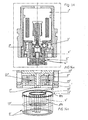
Figures 7 and 8 , a governor valve is shown with acone 18 and a seat, which can be brought to interact with the cone, denoted by 19. The cone is constructed with anouter edge 20, which, in the closing position of the valve, can be brought to bear against atop surface 19a of the seat. The seat is provided with an inward-projectingflange 19b. The seat is thereby arranged with afirst recess 19c of a diameter d3 and asecond recess 19d of a diameter d4. In this case, the cone is constructed with a first disc-shaped or cylindrical part 18a, supporting the saidouter edge 20, and a secondcylindrical part 18b, extending down from the recess of the seat. Thecylindrical part 18b has according to the above the diameter d2, which substantially corresponds to the diameter d4. The diameter d3 exceeds the diameter d2 according toFigure 6 . In this case, the underlap indicated in connection withFigure 6 is so small that it is not apparent in the figure. For the formation of theouter edge 20, the first part 18a is provided with anoblique surface 18c, which merges into the saidcentre part 18b, i.e. that section of the first part 18a which supports the outer edge is tapered. - The
cone 18 is mounted in arecess 21 in ahousing 22, arranged such that it can be screwed in place inside aninsert 23. The arrangement works in known manner together with ashock absorber 24 shown in elementary representation. The piston operates in a workingfluid 25. By means of a top surface 22a in thehousing 22, the maximum stroke s of the cone is determined according to the above. Thecone 18 shall exercise an adjustable resistance to the motions of the piston in the working fluid relative to the cylinder. The main flow q via the valve is conducted between two spaces U' and U'' on the bottom and top side (or input and output) of the valve. In the output position or closing position of the governor valve, the pressures P' and P'' obtain in the said spaces whenever thepiston 26 is accelerated. When the cone assumes an open position, it exercises a resistance against the flow of medium between the spaces U' and U'' according to the above. The shown illustrative embodiment also incorporates apilot valve arrangement 27 for controlling a pilot flow parallel with the said main flow. A solenoid is indicated by 28. With the solenoid, the level of the curves according toFigures 3 and 4 is obtained. The said solenoid, pilot arrangement, adjustment function, housing, insert and shock absorber are well known per se and shall not therefore be described here in greater detail. Reference can be made in this connection toEP 0508465 and0508466 and toJP 09133171-A JP 09112622-A JP 09119472-A JP 09112621-A JP 8121523-A JP 8128489-A - In
Figures 9 and 9a , the valve/cone 18 is arranged such that a bottom surface la of the valve/cone is located in the same plane as those parts of the valve/cone bearing against thetop surface 29 of the seat, i.e. the inner 17 and outer 16 restrictors lie in the same plane. In this case, there is therefore no underlap (uℓ) corresponding to that indicated above. Instead of having the area R2 of the inner restrictor be defined with the aid of the said underlap, acontinuous hole 30 in the seat is in this case utilized, which hole leads into an annular space 1c, compareFigure 9 . Alternatively or supplementary thereto, according toFigure 9a agroove 31 in the bottom surface of the valve/cone can be utilized, which groove can extend diametrically and past the large recess for the fluid in the seat. In the present case, theseat 19 is also provided with anannular recess 19a'. The recesses lc and 19a' face each other and are mutually offset for the formation of the said inner andouter restrictors annular groove 19a', thepart 19 has an inner upward-projecting edge or section, having a thickness t which is less than approx. 1 mm. The inner and outer overlaps measure approx. 0.1 mm. A jet st of fluid indicates that the fluid is prevented by the shapes of the recesses lc and 19a' from actuating the discharge restrictor or from attaching to the cone or seat. -
Figure 10 shows a further alternative to the case in which the inner and outer restrictors of the valve/cone lie in the same plane (compare the case ofFigures 9 and 9a ). In this case, aflexible seat 32 is used, with the characteristic that theedge 33 of the seat by therecess 34 tends to a certain extent to follow the cone as the pressure is altered (e.g. increased), the valve being able to be made more seal tight at stillhigher modulation levels 35, compare the static velocity and force diagram according toFigure 10a . -
Figure 11 shows a valve/cone arrangement in which an adjustingscrew 36 for the adjustment of different levels according toFigure 10a is disposed in a hole in the seat. The adjusting screw is accessible from the outside of the seat. -
Figure 12 shows an example of an underlap uℓ', which is achieved with abush 37 which can be screwed into an internal thread in the seat recess by way of anexternal thread 37a. The hole in the bush runs in towards the cylindrical part of the cone or equivalent. The underlap is situated between the top edge (inner edge) of the bush and the bottom surface of the valve/cone. - The reference notations used in
Figures 1-6 are assignable to the following constructive elements: - with the expression stroke a dynamical change or variation could be interpreted. The word restriction relates to the regulator area or area of adjustment (control). When the restriction is increased the adjustment or control or regulator area is increased, and vice versa. Thus, increasing the restriction relates to the increasing of the restriction or regulator area and decreasing the restriction relates to the decreasing of the restriction area or regulator area. In cases the word restriction is mentioned the involved area is meant. When the expression soft or softer curve formation or shape is discussed the word soft or softer shall be compared with the known dampers. The improved or, new valve according to the present invention allows tailor made curve shapes and is able to work with a large working range. The valve can be made very quick operating, in relation to the known valves.
- The invention relates to a valve which continuously or with minor steps effects its regulation or controlling operation. It can be considered to work essentially without interuptions in its operation state. It works with areas depending on the stroke sizes. In an embodiment the new valve having a chamber which exists between the cone (slide) and the seat (housing). In an embodiment the valve having inner and outer restrictions (part restrictions). However, there is no need for arranging the two or more restrictions as inner and outer restrictions, but they can have another mutually positions, compare the embodiment of
Fig. 14 . -
Fig. 13 shows a complete solenoid controlled pilot operated valve including solenoid 1', pilot valve 2', fail-safe function 3', damping and spring arrangement 4', and main function 5'. Infig 13b is shown a magnified part of the main valve poppet 6'. The inlet jet to the pilot system is here a hole 7'. - Compared with
Fig. 9 the restriction (R2) 8' and the restriction (R1) 9' are in this case forming the inner 10' and an outer 11' ring shaped stroke (s) dependent curtain areas planed on the same plane, which is more clearly shown inFig. 13b . Instead of letting the area in (R2) be defined by the underlap (ul) this embodiment having a hole 12' leading into the ring shaped chamber 13'. The variation of the restrictions (R1) and (R2) are successively making the pressure (pint) 14' inside the chamber to be lower than the regulated pressure (p) 15'. The pressure (pint) is acting on a ring shaped part of the total regulator area (Ad) which is seen in a projected from 16' which the remaining part of the regulator area (A2) is circular shaped 17'. The total regulator force is defined by (p*A2+pint*Ad) and is biasing the sum of other forces from pilot pressure, springs and flow. The size of the areas (A2) and (Ad) is a strong tool to shape and customise the pressure-flow that is force velocity curves of shock. -
Fig 14 shows a further geometry of the valve including a complete known solenoid controlled pilot operated valve having solenoid 1'', pilot valve 2'', fail-safe function 3'', damping and spring arrangement 4'' and main function 5''. InFig. 14a is shown a magnified part of the main valve poppet 6''. The inlet jet to the pilot system is a hole 7''. The by stroke (s) or any restriction unaffected part of the total regulator area (A3) 7'' is distributed on two places on which the regulated pressure (p) 8'' is acting. The varied pressure (pvar) 9'' is reduced due to the opening of the outlet restriction area (R3) 10'' because of a fixed inlet restriction hole 11'' into the ring shaped chamber 12''. A projected part of the regulator area called (A4) 13'' is added to the regulator area (A3). The total regulator force is defined by (A3*p+A4*pint) and is biasing the sum of the other forces from pilot pressure, springs and flow. A regulated main restriction (R4) 14'' is managing the main pressure-flow transformation with a big other diameter and no interference with the moving poppet because of the baffle plate 15'' which is preventing the main flow from passing the holes 16''. This is an advantage due to a clean flow free from turbulence and disturbance flow forces. The holes 16'' are also venting the restriction area (R3). - There are a difference between the above described designs and the design of
figure 14 . (R2) and (R1) are in the designs of earlier described situated in series and both are regulating the main flow. The present (R3) and (R4) ofFigure 14 are completely separated and only (R4) is regulating the main flow.Fig. 14b is to be compared withFig 13b . - The reference notations used in
Figures 1-14b are assignable to the following constructive elements:pressure governor valve 1) main restrictor 2) regulator force 3) supplementary forces 4) character 5) opening point 6) fixed restrictor 7) leak curve 8 springing 9) vibrations 10) opening point 11) regulator function 12) smooth opening 13) new governor valve 14) new regulator force 15) outer edge restrictor 16) inner edge restrictor 17) cone 18) first cylindrical part 18a) second cylindrical part 18b) oblique surface 18c) seat 19) top surface 19a) annular recess 19a') inward-projecting flange 19b) first recess 19c) second recess 19d) outer edge 20) recess 21) housing 22) insert 23) shock absorber 24) working fluid 25) piston 26) pilot valve arrangement 27) solenoid 28) seat top surface 29) seat hole 30) cone groove 31) shim seat 32) seat edge 33) seat recess 34) curve 35) adjusting screw 36) bush 37) upper space U') pressure in upper space p') lower space U'') pressure in lower space p'') stroke S) underlap uℓ, uℓ') fluid jet st) solenoid 1', 1'') pilot valve 2', 2'') fail-safe function 3', 3'') damping and spring arrangement 4', 4'') main function 5', 5'') valve poppet 6', 6'') hole 7', 7'') restriction 8', 8'') restriction 9', 9'') restriction curtain area 10', 11') restriction area 10'') restriction hole 11'') hole 12') chamber 12'') chamber 13') regulator area 13'') pressure 14') restriction 14'') pressure 15') baffle plate 15'') projection 16') hole 16'' regulator area 17') - The invention is not limited to the illustrative embodiment according to the above but can be subject to modifications within the scope of the following patent claims and the inventive, concept.
Claims (6)
- A valve device for a shock absorber (24) comprising a main valve including a first and a second part (18, 6'; 19) forming a restrictor (R1, 16, 11'; R2, 17, 10'), said first part (18, 6') being movable and being adapted to bear against a surface (19a, 19a) of a seat (19), the position of said first part (18) being influenced by strokes of the shock absorber (24) and being determined by the size of the strokes causing a flow (q) of the fluid through the restrictor (R1, 16, 11'; R2, 17, 10'),
characterised in that the position of said first part (18, 6') is furthermore controlled by an equilibrium between a regulator force (15) and a supplementary force created by a solenoid (28, 1") controlled pilot valve arrangement (27),
in that said restrictor is divided in to a down-stream restrictor (R1, 16, 11') and an up-stream restrictor (R2, 17, 10') in view of said flow; and
in that said down-stream part-restrictor (R1, 16, 11') has a larger diameter than that of the up-stream restrictor (R2, 17, 10'); - A valve device according to claim 1, wherein said down-stream part-restrictor (R1, 16, 11') is closed when said first part (18, 6') bears against the surface (19a, 19a', 29) of said seat (19).
- A valve device according to claim 1 or 2, wherein the size of the down-stream restrictor (R1, 16, 11') and the size of the up-stream restrictor (R2, 17, 10') is altered in at least the introductory and concluding part of the opening and closing function, respectively, together defining a restrictor function.
- A valve device according to any one of claims 1 to 3, wherein said up-stream restrictor (R2, 17, 10') has a size which is increased in relative terms in such a way that it has no substantial effect on the restrictor function and when the stroke is larger, has a size which is reduced in relative terms, such that it dominates the restrictor function; and
in that the down-stream part-restrictor (R1, 16, 11') has a size which is increased in relative terms, in such a way that its effect is reduced upon the restrictor function, for achieving a smooth opening and closing operation, respectively. - A valve device according to any one of the preceding claims, wherein said pilot valve arrangement (27, 2') is provided for creating a pilot flow parallel to said flow (q).
- A valve device according to any one of the preceding claims, wherein said first part (18, 6') is provided with a central hole (7') for creating an inlet for the pilot flow.
Priority Applications (1)
| Application Number | Priority Date | Filing Date | Title |
|---|---|---|---|
| EP08000535A EP2028391B1 (en) | 1998-03-10 | 1999-02-18 | Device and application involving two parts working away from and towards each other and energy absorbing device |
Applications Claiming Priority (2)
| Application Number | Priority Date | Filing Date | Title |
|---|---|---|---|
| SE9800775 | 1998-03-10 | ||
| SE9800775A SE523534C2 (en) | 1998-03-10 | 1998-03-10 | Valve or pressure regulator device for effecting opening and / or closing functions or movements for two parts working against each other, eg cone / slide and seat / housing respectively. |
Related Child Applications (1)
| Application Number | Title | Priority Date | Filing Date |
|---|---|---|---|
| EP08000535A Division EP2028391B1 (en) | 1998-03-10 | 1999-02-18 | Device and application involving two parts working away from and towards each other and energy absorbing device |
Publications (3)
| Publication Number | Publication Date |
|---|---|
| EP0942195A2 EP0942195A2 (en) | 1999-09-15 |
| EP0942195A3 EP0942195A3 (en) | 2002-04-17 |
| EP0942195B1 true EP0942195B1 (en) | 2008-07-02 |
Family
ID=20410485
Family Applications (2)
| Application Number | Title | Priority Date | Filing Date |
|---|---|---|---|
| EP99850025A Expired - Lifetime EP0942195B1 (en) | 1998-03-10 | 1999-02-18 | Valve device for a shock absorber |
| EP08000535A Expired - Lifetime EP2028391B1 (en) | 1998-03-10 | 1999-02-18 | Device and application involving two parts working away from and towards each other and energy absorbing device |
Family Applications After (1)
| Application Number | Title | Priority Date | Filing Date |
|---|---|---|---|
| EP08000535A Expired - Lifetime EP2028391B1 (en) | 1998-03-10 | 1999-02-18 | Device and application involving two parts working away from and towards each other and energy absorbing device |
Country Status (5)
| Country | Link |
|---|---|
| US (1) | US6311812B1 (en) |
| EP (2) | EP0942195B1 (en) |
| JP (1) | JP3655489B2 (en) |
| DE (1) | DE69938984D1 (en) |
| SE (1) | SE523534C2 (en) |
Cited By (1)
| Publication number | Priority date | Publication date | Assignee | Title |
|---|---|---|---|---|
| EP3208489A1 (en) | 2016-02-22 | 2017-08-23 | Öhlins Racing Ab | Soft opening 2-way valve arrangement for a shock absorber |
Families Citing this family (17)
| Publication number | Priority date | Publication date | Assignee | Title |
|---|---|---|---|---|
| FR2838172B1 (en) | 2002-04-05 | 2004-07-02 | Jacques Sirven | SHOCK ABSORBER, PARTICULARLY FOR MOTOR VEHICLE |
| JP4491270B2 (en) * | 2004-04-26 | 2010-06-30 | カヤバ工業株式会社 | Hydraulic shock absorber |
| DE102006016473A1 (en) * | 2005-12-08 | 2007-06-14 | Continental Teves Ag & Co. Ohg | Pressure regulating valve e.g. for variable adjustment of damping characteristic of vibration damper, has flexible element with defined force and movement behavior arranged between second piston sealing surface and second sealing seat |
| JP5145575B2 (en) * | 2008-05-19 | 2013-02-20 | ヤマハ発動機株式会社 | Shock absorber and vehicle equipped with the same |
| SE532533C2 (en) | 2008-06-25 | 2010-02-16 | Oehlins Racing Ab | Pressure regulator for shock absorbers |
| SE533996C2 (en) * | 2009-04-23 | 2011-03-22 | Oehlins Racing Ab | Pressure regulator in a shock absorber valve |
| EP2446168B1 (en) * | 2009-06-25 | 2014-03-05 | Öhlins Racing Ab | Pressure regulator comprising an actuator |
| US8235186B2 (en) * | 2009-10-07 | 2012-08-07 | Multimatic Inc. | Hydraulic damper spool valve |
| US8800732B2 (en) | 2011-02-25 | 2014-08-12 | Multimatic Inc. | Hydraulic damper spool valve |
| JP5912523B2 (en) * | 2011-12-28 | 2016-04-27 | 日本サーモスタット株式会社 | Fluid control valve |
| FR3020104B1 (en) * | 2014-04-16 | 2017-08-11 | Jacques Sirven | HYDRAULIC SHOCK ABSORBER WITH COMPRESSION FILTERING |
| US9772042B2 (en) | 2014-07-10 | 2017-09-26 | Honeywell International Inc. | Fluid flow control devices and systems |
| JP6417170B2 (en) | 2014-09-30 | 2018-10-31 | 株式会社ショーワ | Shock absorber |
| DE102014116264A1 (en) | 2014-11-07 | 2016-05-12 | Thyssenkrupp Ag | Adjustable vibration damper for motor vehicles |
| JP6468016B2 (en) * | 2015-03-18 | 2019-02-13 | アイシン精機株式会社 | Shock absorber |
| RU177997U1 (en) * | 2017-04-05 | 2018-03-19 | Общество с ограниченной ответственностью "Литмаш-М" | FIRE VALVE |
| US11773940B2 (en) | 2020-03-04 | 2023-10-03 | Multimatic Inc. | Advanced hydraulic damper spool valve |
Family Cites Families (13)
| Publication number | Priority date | Publication date | Assignee | Title |
|---|---|---|---|---|
| US209290A (en) * | 1878-10-22 | Improvement in globe-valves | ||
| US1634360A (en) * | 1926-05-28 | 1927-07-05 | Holzwarth Gas Turbine Co | Valve |
| US4531708A (en) * | 1984-08-21 | 1985-07-30 | Honeywell Lucifer Sa | Solenoid valve |
| ES2030526T3 (en) * | 1988-02-15 | 1992-11-01 | Bendix Espana S.A. | VARIABLE REGIME SHOCK ABSORBER. |
| KR930006510B1 (en) * | 1988-07-29 | 1993-07-16 | 미쓰비시전기 주식회사 | Solenoid valve |
| DE3922155C2 (en) * | 1989-07-06 | 1999-08-26 | Mannesmann Sachs Ag | magnetic valve |
| DE3942545A1 (en) * | 1989-12-22 | 1991-06-27 | Bosch Gmbh Robert | PRESSURE ACTUATED VALVE |
| JPH04312226A (en) * | 1991-04-12 | 1992-11-04 | Oehlins Racing Ab | Attenuator |
| DE4123141C1 (en) * | 1991-07-12 | 1992-07-30 | Boge Ag, 5208 Eitorf, De | |
| US5163538A (en) * | 1991-09-03 | 1992-11-17 | General Motors Company | Low level damping valve and method for a semi-active hydraulic damper |
| US5251370A (en) * | 1991-10-31 | 1993-10-12 | Profil Verbindungstechnik Gmbh & Co. | Method of attaching a fastening element to a panel |
| JP3146392B2 (en) * | 1992-11-20 | 2001-03-12 | トキコ株式会社 | Damping force adjustable hydraulic shock absorber |
| US5871109A (en) * | 1996-08-05 | 1999-02-16 | Emerald Rail Technologies, Llc | Railcar cushion device preload valving systems |
-
1998
- 1998-03-10 SE SE9800775A patent/SE523534C2/en not_active IP Right Cessation
-
1999
- 1999-02-18 DE DE69938984T patent/DE69938984D1/en not_active Expired - Lifetime
- 1999-02-18 EP EP99850025A patent/EP0942195B1/en not_active Expired - Lifetime
- 1999-02-18 EP EP08000535A patent/EP2028391B1/en not_active Expired - Lifetime
- 1999-02-24 US US09/256,172 patent/US6311812B1/en not_active Expired - Lifetime
- 1999-03-04 JP JP10306399A patent/JP3655489B2/en not_active Expired - Lifetime
Cited By (5)
| Publication number | Priority date | Publication date | Assignee | Title |
|---|---|---|---|---|
| EP3208489A1 (en) | 2016-02-22 | 2017-08-23 | Öhlins Racing Ab | Soft opening 2-way valve arrangement for a shock absorber |
| WO2017144444A1 (en) | 2016-02-22 | 2017-08-31 | öHLINS RACING AB | Soft opening 2-way valve arrangement for a shock absorber |
| WO2017144445A1 (en) | 2016-02-22 | 2017-08-31 | öHLINS RACING AB | 2-way soft opening valve arrangement for a shock absorber |
| US10801576B2 (en) | 2016-02-22 | 2020-10-13 | Ohlins Racing Ab | 2-way soft opening valve arrangement for a shock absorber |
| US10989266B2 (en) | 2016-02-22 | 2021-04-27 | öHLINS RACING AB | Soft opening 2-way valve arrangement for a shock absorber |
Also Published As
| Publication number | Publication date |
|---|---|
| US6311812B1 (en) | 2001-11-06 |
| SE523534C2 (en) | 2004-04-27 |
| JP3655489B2 (en) | 2005-06-02 |
| EP0942195A2 (en) | 1999-09-15 |
| EP2028391B1 (en) | 2012-02-01 |
| DE69938984D1 (en) | 2008-08-14 |
| SE9800775D0 (en) | 1998-03-10 |
| SE9800775L (en) | 1999-09-11 |
| JPH11315874A (en) | 1999-11-16 |
| EP2028391A1 (en) | 2009-02-25 |
| EP0942195A3 (en) | 2002-04-17 |
Similar Documents
| Publication | Publication Date | Title |
|---|---|---|
| EP0942195B1 (en) | Valve device for a shock absorber | |
| KR100265654B1 (en) | Daempfventil mit veraendrbarer daempfkraft | |
| US8794405B2 (en) | Damping force control type shock absorber | |
| US6079526A (en) | Damping force control type hydraulic shock absorber | |
| US4356898A (en) | Valve assembly and reduced harshness shock absorber embodying the same | |
| KR100347779B1 (en) | Hydraulic damper of damping force adjusting type | |
| US5975258A (en) | Damping force control type hydraulic shock absorber | |
| US5911290A (en) | Step motor actuated continuous variable shock absorber | |
| JPH0356334B2 (en) | ||
| JPH0396730A (en) | Valve for hydraulic fluid and shock absorber including the same | |
| US20070144848A1 (en) | Hydraulic damper for vehicle | |
| US10801576B2 (en) | 2-way soft opening valve arrangement for a shock absorber | |
| JP2001159444A (en) | Damping force adjusting type hydraulic shock absorber | |
| JP5851159B2 (en) | Shock absorber | |
| JPH0727164A (en) | Valve structure of shock absorber | |
| JP2002013579A (en) | Damping force regulation type hydraulic shock absorber | |
| JPH1182602A (en) | Damping force control type hydraulic shock absorber | |
| JP2001041272A (en) | Damping force adjustment type hydraulic buffer | |
| JP2517796Y2 (en) | Hydraulic shock absorber | |
| JPS6342134B2 (en) | ||
| JPH09133171A (en) | Variable damping force hydraulic shock absorber | |
| JPH05302639A (en) | Hydraulic damper | |
| JP2001146937A (en) | Damping force regulating type hydraulic shock absorber | |
| JP2001012531A (en) | Double cylinder type hydraulic damper | |
| JP2002227903A (en) | Valve structure of hydraulic shock absorber |
Legal Events
| Date | Code | Title | Description |
|---|---|---|---|
| PUAI | Public reference made under article 153(3) epc to a published international application that has entered the european phase |
Free format text: ORIGINAL CODE: 0009012 |
|
| AK | Designated contracting states |
Kind code of ref document: A2 Designated state(s): AT BE CH CY DE DK ES FI FR GB GR IE IT LI LU MC NL PT SE Kind code of ref document: A2 Designated state(s): DE FR GB IT NL |
|
| AX | Request for extension of the european patent |
Free format text: AL;LT;LV;MK;RO;SI |
|
| PUAL | Search report despatched |
Free format text: ORIGINAL CODE: 0009013 |
|
| AK | Designated contracting states |
Kind code of ref document: A3 Designated state(s): AT BE CH CY DE DK ES FI FR GB GR IE IT LI LU MC NL PT SE |
|
| AX | Request for extension of the european patent |
Free format text: AL;LT;LV;MK;RO;SI |
|
| RIC1 | Information provided on ipc code assigned before grant |
Free format text: 7F 16F 9/508 A, 7F 16F 9/512 B, 7F 16F 9/48 B |
|
| 17P | Request for examination filed |
Effective date: 20020626 |
|
| AKX | Designation fees paid |
Free format text: DE FR GB IT NL |
|
| 17Q | First examination report despatched |
Effective date: 20040429 |
|
| GRAP | Despatch of communication of intention to grant a patent |
Free format text: ORIGINAL CODE: EPIDOSNIGR1 |
|
| RTI1 | Title (correction) |
Free format text: VALVE DEVICE FOR A SHOCK ABSORBER |
|
| GRAS | Grant fee paid |
Free format text: ORIGINAL CODE: EPIDOSNIGR3 |
|
| GRAA | (expected) grant |
Free format text: ORIGINAL CODE: 0009210 |
|
| AK | Designated contracting states |
Kind code of ref document: B1 Designated state(s): DE FR GB IT NL |
|
| REG | Reference to a national code |
Ref country code: GB Ref legal event code: FG4D |
|
| REF | Corresponds to: |
Ref document number: 69938984 Country of ref document: DE Date of ref document: 20080814 Kind code of ref document: P |
|
| PLBE | No opposition filed within time limit |
Free format text: ORIGINAL CODE: 0009261 |
|
| STAA | Information on the status of an ep patent application or granted ep patent |
Free format text: STATUS: NO OPPOSITION FILED WITHIN TIME LIMIT |
|
| 26N | No opposition filed |
Effective date: 20090403 |
|
| REG | Reference to a national code |
Ref country code: FR Ref legal event code: PLFP Year of fee payment: 18 |
|
| REG | Reference to a national code |
Ref country code: FR Ref legal event code: PLFP Year of fee payment: 19 |
|
| REG | Reference to a national code |
Ref country code: FR Ref legal event code: PLFP Year of fee payment: 20 |
|
| PGFP | Annual fee paid to national office [announced via postgrant information from national office to epo] |
Ref country code: NL Payment date: 20180214 Year of fee payment: 20 |
|
| PGFP | Annual fee paid to national office [announced via postgrant information from national office to epo] |
Ref country code: GB Payment date: 20180126 Year of fee payment: 20 Ref country code: DE Payment date: 20180123 Year of fee payment: 20 |
|
| PGFP | Annual fee paid to national office [announced via postgrant information from national office to epo] |
Ref country code: IT Payment date: 20180123 Year of fee payment: 20 Ref country code: FR Payment date: 20180119 Year of fee payment: 20 |
|
| REG | Reference to a national code |
Ref country code: DE Ref legal event code: R071 Ref document number: 69938984 Country of ref document: DE |
|
| REG | Reference to a national code |
Ref country code: NL Ref legal event code: MK Effective date: 20190217 |
|
| REG | Reference to a national code |
Ref country code: GB Ref legal event code: PE20 Expiry date: 20190217 |
|
| PG25 | Lapsed in a contracting state [announced via postgrant information from national office to epo] |
Ref country code: GB Free format text: LAPSE BECAUSE OF EXPIRATION OF PROTECTION Effective date: 20190217 |