EP0942155B1 - Internal combustion engine with anti-foaming device - Google Patents
Internal combustion engine with anti-foaming device Download PDFInfo
- Publication number
- EP0942155B1 EP0942155B1 EP19990400616 EP99400616A EP0942155B1 EP 0942155 B1 EP0942155 B1 EP 0942155B1 EP 19990400616 EP19990400616 EP 19990400616 EP 99400616 A EP99400616 A EP 99400616A EP 0942155 B1 EP0942155 B1 EP 0942155B1
- Authority
- EP
- European Patent Office
- Prior art keywords
- screen
- internal combustion
- combustion engine
- oil
- forming means
- Prior art date
- Legal status (The legal status is an assumption and is not a legal conclusion. Google has not performed a legal analysis and makes no representation as to the accuracy of the status listed.)
- Expired - Lifetime
Links
- 238000002485 combustion reaction Methods 0.000 title claims description 20
- 230000003254 anti-foaming effect Effects 0.000 title 1
- 239000000463 material Substances 0.000 claims description 3
- 239000002991 molded plastic Substances 0.000 claims description 3
- 238000007789 sealing Methods 0.000 claims description 2
- 230000002093 peripheral effect Effects 0.000 description 4
- 238000012423 maintenance Methods 0.000 description 2
- 239000004952 Polyamide Substances 0.000 description 1
- 230000005587 bubbling Effects 0.000 description 1
- 230000006835 compression Effects 0.000 description 1
- 238000007906 compression Methods 0.000 description 1
- 238000006073 displacement reaction Methods 0.000 description 1
- 230000005489 elastic deformation Effects 0.000 description 1
- 239000000806 elastomer Substances 0.000 description 1
- 229920001971 elastomer Polymers 0.000 description 1
- 238000001914 filtration Methods 0.000 description 1
- 239000003365 glass fiber Substances 0.000 description 1
- 230000005484 gravity Effects 0.000 description 1
- 238000005461 lubrication Methods 0.000 description 1
- 238000004519 manufacturing process Methods 0.000 description 1
- 238000005192 partition Methods 0.000 description 1
- 229920002647 polyamide Polymers 0.000 description 1
- 230000002265 prevention Effects 0.000 description 1
Images
Classifications
-
- F—MECHANICAL ENGINEERING; LIGHTING; HEATING; WEAPONS; BLASTING
- F01—MACHINES OR ENGINES IN GENERAL; ENGINE PLANTS IN GENERAL; STEAM ENGINES
- F01M—LUBRICATING OF MACHINES OR ENGINES IN GENERAL; LUBRICATING INTERNAL COMBUSTION ENGINES; CRANKCASE VENTILATING
- F01M11/00—Component parts, details or accessories, not provided for in, or of interest apart from, groups F01M1/00 - F01M9/00
- F01M11/0004—Oilsumps
-
- F—MECHANICAL ENGINEERING; LIGHTING; HEATING; WEAPONS; BLASTING
- F01—MACHINES OR ENGINES IN GENERAL; ENGINE PLANTS IN GENERAL; STEAM ENGINES
- F01M—LUBRICATING OF MACHINES OR ENGINES IN GENERAL; LUBRICATING INTERNAL COMBUSTION ENGINES; CRANKCASE VENTILATING
- F01M11/00—Component parts, details or accessories, not provided for in, or of interest apart from, groups F01M1/00 - F01M9/00
- F01M11/06—Means for keeping lubricant level constant or for accommodating movement or position of machines or engines
- F01M11/062—Accommodating movement or position of machines or engines, e.g. dry sumps
- F01M11/064—Movement
-
- F—MECHANICAL ENGINEERING; LIGHTING; HEATING; WEAPONS; BLASTING
- F01—MACHINES OR ENGINES IN GENERAL; ENGINE PLANTS IN GENERAL; STEAM ENGINES
- F01M—LUBRICATING OF MACHINES OR ENGINES IN GENERAL; LUBRICATING INTERNAL COMBUSTION ENGINES; CRANKCASE VENTILATING
- F01M11/00—Component parts, details or accessories, not provided for in, or of interest apart from, groups F01M1/00 - F01M9/00
- F01M11/0004—Oilsumps
- F01M2011/005—Oilsumps with special anti-turbulence means, e.g. anti-foaming means or intermediate plates
-
- F—MECHANICAL ENGINEERING; LIGHTING; HEATING; WEAPONS; BLASTING
- F01—MACHINES OR ENGINES IN GENERAL; ENGINE PLANTS IN GENERAL; STEAM ENGINES
- F01M—LUBRICATING OF MACHINES OR ENGINES IN GENERAL; LUBRICATING INTERNAL COMBUSTION ENGINES; CRANKCASE VENTILATING
- F01M11/00—Component parts, details or accessories, not provided for in, or of interest apart from, groups F01M1/00 - F01M9/00
- F01M11/0004—Oilsumps
- F01M2011/0054—Fastening to the cylinder block
Definitions
- the present invention relates to the field anti-bubbling devices mounted in the oil sumps of internal combustion engines intended in particular to equip vehicles automobiles.
- An internal combustion engine includes, in general, a cylinder block receiving a cylinder head its upper end and an oil pan at its lower end.
- the lubrication circuit of such an engine conventionally comprises a pump driven by the crankshaft and which sucks the oil stored in the oil pan to send it, after filtration, through pipes suitable for moving engine parts, such as crankshaft bearings, connecting rods, pistons or camshaft, oil returns then by gravity in the oil pan.
- Document FR-A-2.650.033 discloses by example, a screen in the form of a plate in shaped sheet to protect crankshaft and crankshaft, oil contained in the crankcase oil and oil falling from the cylinder head.
- the splash screens are fixed by screws directly on the bearing caps of the crankshaft or even directly on corresponding bosses carried by the housing oil or the cylinder block.
- Such a provision has the disadvantage of complicating motor assembly and increase the cost of this last.
- the object of the present invention is to remedy this drawback by proposing an engine with an easy-to-splash prevention device mount and requiring no fixing means reported.
- the internal combustion engine according to the invention is of the type comprising a cylinder block inside which is housed a crankshaft connected to pistons by connecting rods, a oil pan and means forming an anti-splash screen to prevent the oil slick contained in the oil pan to come into contact with the crankshaft and connecting rods.
- the means forming a screen are immobilized in position simply by pinching of a plurality of holding tabs between the lower edge of the cylinder block and the corresponding edge of the oil pan.
- the legs support are housed in a groove corresponding seal interposed between the oil pan and the cylinder block.
- the positioning of the screen means is ensured by ribs extending under the legs of maintenance.
- the means forming a screen include housings intended for come to fit on bearing caps of the crankshaft to ensure prepositioning during their mounting on the cylinder block.
- the means forming a screen have fixing arms clip-on allowing their hanging on the cylinder block.
- the means forming a screen have boxes open towards the oil pan intended in particular to limit the displacement of the oil slick.
- the means forming a screen are formed by a monobloc shell obtained in molded plastic.
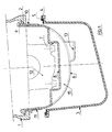
- the base of the cylinder block 1 has a peripheral edge or sidewalk 2 extending in projecting perpendicular to the side walls of the cylinder block 1 towards the inside of the latter, towards the crankshaft. against this edge peripheral 2 of cylinder block 1 comes to take press the corresponding peripheral edge 4 of the oil pan 3.
- the fixing of the oil sump 3 on the cylinder block 1 is secured by screws not figured cooperating with the peripheral edges above 2 and 4 forming a flange and counter flange.
- a type 5 seal elastomer housed in a groove formed on the edge device 4 of the oil pan 3. Dimensions of seal 5 are suitable for obtaining a rate predetermined compression when the edge device 4 comes into contact with edge 2.
- an anti-splash screen 6 is interposed between the cylinder block 1 and the oil pan 3 in order to prevent the oil in the oil pan does not come into contact with the crankshaft and crankshaft.
- This anti-splash screen 6 is produced in the form a one-piece molded plastic shell, such as a glass fiber filled polyamide. Screen 6 is shaped to wrap around the bottom of the crankshaft not shown and also the crankshaft not shown.
- the anti-splash screen 6 has a shape general semi-cylindrical corresponding substantially to the envelope curve of the trajectories crankshaft and crankshaft. The dimensions of screen 6 are adjusted to leave a clearance extremely reduced between screen and hitch mobile of the order of a few millimeters.
- Screen 6 has openings 13 arranged substantially under each of the connecting rods. These openings are oriented transversely in the direction of motor rotation, to evacuate oil splashes from the lower engine (piston, connecting rods, journals, crank pins, etc.) to the housing oil.
- Screen 6 following the shape of the hitch mobile has walls 8 facing crankshaft bearing caps. These walls 8 form transverse boxes 15 open at direction of the oil pan. The boxes 15 isolate the crankshaft peer to peer and the connecting rod of the oil slick and on the other hand they make it possible to stiffen the screen 6.
- the boxes 15 define on the other hand partitions on the underside of screen 6 which have the advantage of limiting the movement of the oil slick in the sump oil 3 and therefore planing. So the pump aspiration remains primed even in case of significant movements of the oil.
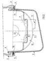
- Immobilization in position of the screen 6 is ensured by a plurality of lugs holding 10 projecting transversely relative to to the side edges of the screen 6 which come pinch between the edge 2 arranged at the base of the cylinder block 1 and the edge corresponds 4 to the housing oil 1 with interposition of the seal 5.
- the seal 5 presents a transversely opening groove suitable for receive the retaining tabs 10. It is thus possible to tighten the holding tabs 10 of the splash screen 6 without affecting the tightness of the oil pan assembly 3 on the cylinder block 1.
- cleats or ribs of positioning 11 are arranged under the legs of maintenance 10. These cleats are intended to come immobilize the side edges of the screen 6 against the corresponding side edges of the oil pan 3.
- the anti-splash screen 6 presents by elsewhere clipping arms 9 allowing the holding the screen on the cylinder block when disassembly of the oil pan 3 or during engine assembly operations on chains mounting.
- the arms 9 which are shaped for have some elasticity, whatever the material used, have at their end a protruding rim intended to come to rest on the edge 2 formed at the base of the cylinder block 1.
- the present invention applies also for engines with housing beams cap interposed between the cylinder block and the oil pan.
- the mounting of the screen is operated between the hat beam and the oil pan.
Description
La présente invention concerne le domaine des dispositifs anti-barbotage montés dans les carters d'huile de moteurs à combustion interne destinés notamment à équiper les véhicules automobiles.The present invention relates to the field anti-bubbling devices mounted in the oil sumps of internal combustion engines intended in particular to equip vehicles automobiles.
Un moteur à combustion interne comprend, en général, un carter-cylindres recevant une culasse à son extrémité supérieure et un carter d'huile à son extrémité inférieure. Le circuit de lubrification d'un tel moteur comprend classiquement une pompe entraínée par le vilebrequin et qui aspire l'huile stockée dans le carter d'huile pour l'envoyer, après filtration, à travers des conduites appropriées vers les pièces mobiles du moteur, comme les paliers de vilebrequin, les bielles, les pistons ou l'arbre à cames, l'huile retourne ensuite par gravité dans le carter d'huile.An internal combustion engine includes, in general, a cylinder block receiving a cylinder head its upper end and an oil pan at its lower end. The lubrication circuit of such an engine conventionally comprises a pump driven by the crankshaft and which sucks the oil stored in the oil pan to send it, after filtration, through pipes suitable for moving engine parts, such as crankshaft bearings, connecting rods, pistons or camshaft, oil returns then by gravity in the oil pan.
La nappe d'huile contenue dans le carter d'huile étant soumise aux mouvements du véhicule, se déplace et est donc susceptible de venir au contact du vilebrequin et de l'embiellage avec pour conséquence une perte de puissance résultant d'un tel barbotage. Pour prévenir ce phénomène, il est connu de disposer un écran venant isoler le vilebrequin et l'embiellage de la nappe d'huile contenue dans le carter d'huile.The oil slick contained in the sump of oil being subjected to the movements of the vehicle, moves and is therefore likely to come to crankshaft and crankshaft contact with for consequence a loss of power resulting from a such bubbling. To prevent this phenomenon, it is known to have a screen isolating the crankshaft and the connecting rod of the oil slick contained in the oil pan.
Le document FR-A-2.650.033 divulgue par exemple, un écran sous la forme d'une plaque en tôle conformée pour protéger l'embiellage et le vilebrequin, de l'huile contenue dans le carter d'huile et de l'huile retombant de la culasse.Document FR-A-2.650.033 discloses by example, a screen in the form of a plate in shaped sheet to protect crankshaft and crankshaft, oil contained in the crankcase oil and oil falling from the cylinder head.
Conformément à l'état de la technique connue, les écrans anti-barbotage sont fixés par des vis directement sur les chapeaux de palier du vilebrequin ou bien encore directement sur des bossages correspondants portés par le carter d'huile ou le carter-cylindres. Une telle disposition présente l'inconvénient de compliquer l'assemblage du moteur et de renchérir le coût de ce dernier.In accordance with the state of the art known, the splash screens are fixed by screws directly on the bearing caps of the crankshaft or even directly on corresponding bosses carried by the housing oil or the cylinder block. Such a provision has the disadvantage of complicating motor assembly and increase the cost of this last.
La présente invention a pour objet de remédier à cet inconvénient en proposant un moteur comportant un dispositif anti-barbotage facile à monter et ne nécessitant aucun moyen de fixation rapporté.The object of the present invention is to remedy this drawback by proposing an engine with an easy-to-splash prevention device mount and requiring no fixing means reported.
Le moteur à combustion interne selon l'invention est du type comportant un carter-cylindres à l'intérieur duquel est logé un vilebrequin relié à des pistons par des bielles, un carter d'huile et des moyens formant écran anti-barbotage pour empêcher la nappe d'huile contenue dans le carter d'huile de venir au contact du vilebrequin et des bielles.The internal combustion engine according to the invention is of the type comprising a cylinder block inside which is housed a crankshaft connected to pistons by connecting rods, a oil pan and means forming an anti-splash screen to prevent the oil slick contained in the oil pan to come into contact with the crankshaft and connecting rods.
Selon l'invention, les moyens formant écran sont immobilisés en position simplement par pincement d'une pluralité de pattes de maintien entre le bord inférieur du carter-cylindres et le bord correspondant du carter d'huile. According to the invention, the means forming a screen are immobilized in position simply by pinching of a plurality of holding tabs between the lower edge of the cylinder block and the corresponding edge of the oil pan.
Selon une autre caractéristique du moteur à combustion interne objet de l'invention, les pattes de maintien sont logées dans une gorge correspondante du joint d'étanchéité interposé entre le carter d'huile et le carter-cylindres.According to another characteristic of the internal combustion object of the invention, the legs support are housed in a groove corresponding seal interposed between the oil pan and the cylinder block.
Selon une autre caractéristique du moteur à combustion interne objet de l'invention, le positionnement des moyens formant écran est assuré par des nervures s'étendant sous les pattes de maintien.According to another characteristic of the internal combustion object of the invention, the positioning of the screen means is ensured by ribs extending under the legs of maintenance.
Selon une autre caractéristique du moteur à combustion interne objet de l'invention, les moyens formant écran comportent des logements destinés à venir s'emboíter sur des chapeaux de palier du vilebrequin afin d'assurer un prépositionnement lors de leur montage sur le carter-cylindres.According to another characteristic of the internal combustion object of the invention, the means forming a screen include housings intended for come to fit on bearing caps of the crankshaft to ensure prepositioning during their mounting on the cylinder block.
Selon une autre caractéristique du moteur à combustion interne objet de l'invention, les moyens formant écran comportent des bras de fixation clipsables permettant leur accrochage sur le carter-cylindres.According to another characteristic of the internal combustion object of the invention, the means forming a screen have fixing arms clip-on allowing their hanging on the cylinder block.
Selon une autre caractéristique du moteur à combustion interne objet de l'invention, les moyens formant écran comportent des caissons ouverts vers le carter d'huile destinés notamment à limiter les déplacements de la nappe d'huile.According to another characteristic of the internal combustion object of the invention, the means forming a screen have boxes open towards the oil pan intended in particular to limit the displacement of the oil slick.
Selon une autre caractéristique du moteur à combustion interne objet de l'invention, les moyens formant écran sont formés par une coque monobloc obtenue en plastique moulé. According to another characteristic of the internal combustion object of the invention, the means forming a screen are formed by a monobloc shell obtained in molded plastic.
On comprendra mieux les buts, aspects et avantages de la présente invention, d'après la description donnée ci-après d'un mode de réalisation de l'invention, donné à titre d'exemple non limitatif, en se référant aux dessins annexés, dans lesquels :
- la figure 1 est une vue en coupe transversale partielle d'un carter-cylindres et d'un carter d'huile d'un moteur à combustion interne équipé d'un écran anti-barbotage selon l'invention ;
- la figure 2 est une vue similaire à la figure 1 précisant le montage de la plaque anti-barbotage entre le carter-cylindres et le carter d'huile.
- Figure 1 is a partial cross-sectional view of a cylinder block and an oil pan of an internal combustion engine equipped with an anti-bubbling screen according to the invention;
- Figure 2 is a view similar to Figure 1 showing the mounting of the anti-bubbling plate between the cylinder block and the oil pan.
Conformément aux figures, seuls les éléments du moteur nécessaires à la compréhension de l'invention ont été figurés, de plus pour en faciliter la lecture les mêmes éléments portent les mêmes références d'une figure à l'autre.According to the figures, only the elements of the engine necessary for understanding of the invention have been figured, moreover in facilitate reading the same elements bear the same references from one figure to another.
En se reportant à la figure 1, on a
représenté l'extrémité inférieure formant embase
d'un carter-cylindres 1 de moteur à combustion
interne de type multicylindre en ligne. A
l'intérieur de ce carter-cylindres sont logés de
façon classique des pistons reliés à un vilebrequin
par des bielles.Referring to Figure 1, we have
shown the lower end forming a base
of a combustion
L'embase du carter-cylindres 1 présente un
bord périphérique ou trottoir 2 s'étendant en
saillie perpendiculairement aux parois latérales du
carter-cylindres 1 vers l'intérieur de ce dernier,
en direction du vilebrequin. Contre ce bord
périphérique 2 du carter-cylindres 1 vient prendre
appui le bord périphérique correspondant 4 du
carter d'huile 3.The base of the
La fixation du carter d'huile 3 sur le
carter-cylindres 1 est assurée par des vis non
figurées coopérant avec les bords périphériques
précités 2 et 4 formant bride et contrebride. Entre
le carter-cylindres 1 et le carter d'huile 3 est
interposé un joint d'étanchéité 5 de type
élastomère logé dans une gorge ménagée sur le bord
périphérique 4 du carter d'huile 3. Les dimensions
du joint 5 sont adaptées pour obtenir un taux
prédéterminé de compression lorsque le bord
périphérique 4 vient au contact du bord 2.The fixing of the
Conformément à l'invention, un écran anti-barbotage
6 est interposé entre le carter-cylindres
1 et le carter d'huile 3 et ce, afin d'éviter que
l'huile contenue dans le carter d'huile n'entre en
contact avec le vilebrequin et l'embiellage. Cet
écran anti-barbotage 6 est réalisé sous la forme
d'une coque monobloc en plastique moulé, tel qu'un
polyamide chargé fibres de verre. L'écran 6 est
conformée pour envelopper la partie inférieure du
vilebrequin non figuré et de l'embiellage également
non figuré.According to the invention, an
L'écran anti-barbotage 6 à une forme
générale semi-cylindrique correspondant
sensiblement à la courbe enveloppe des trajectoires
du vilebrequin et de l'embiellage. Les dimensions
de l'écran 6 sont ajustés pour laisser un jeu
extrêmement réduit entre l'écran et l'attelage
mobile de l'ordre de quelques millimètres.The
L'écran 6 présentent des ouvertures 13
agencées sensiblement sous chacune des bielles. Ces
ouvertures sont orientées transversalement dans le
sens de rotation du moteur, pour évacuer les
projections d'huile issues du bas moteur (piston,
bielles, tourillons, manetons, etc.) vers le carter
d'huile.
L'écran 6 épousant la forme de l'attelage
mobile présente des parois 8 faisant face aux
chapeaux de palier du vilebrequin. Ces parois 8
forment des caissons transversaux 15 ouverts en
direction du carter d'huile. Les caissons 15
permettent d'isoler poste à poste le vilebrequin et
l'embiellage de la nappe d'huile et d'autre part
ils permettent de rigidifier l'écran 6.
Les caissons 15 définissent d'autre part
des cloisonnements sur la face inférieure de
l'écran 6 qui présentent l'avantage de limiter le
mouvement de la nappe d'huile dans le carter
d'huile 3 et donc le déjaugeage. Ainsi la pompe
d'aspiration reste amorcée même en cas de
mouvements importants de l'huile.The
Tout ou partie des parois 8 présentent par
ailleurs des épaulements 7 venant encadrées les
bords latéraux des chapeaux de palier 12. Ces
épaulements permettent ainsi d'opérer le
prépositionnement de l'écran 6 sur les chapeaux de
palier lors de son montage sur le carter-cylindres
1.All or part of the
L'immobilisation en position de l'écran 6
est assurée grâce à une pluralité de pattes de
maintien 10 en saillie transversalement par rapport
aux bords latéraux de l'écran 6 qui viennent se
pincer entre le bord 2 agencé à l'embase du carter-cylindres
1 et le bord correspond 4 du carter
d'huile 1 avec interposition du joint d'étanchéité
5.Immobilization in position of the
Pour ce faire, le joint 5 présente une
gorge débouchant transversalement adaptée pour
recevoir les pattes de maintien 10. Il est ainsi
possible d'opérer le serrage des pattes de maintien
10 de l'écran anti-barbotage 6 sans affecter
l'étanchéité du montage du carter d'huile 3 sur le
carter-cylindres 1.To do this, the
Ainsi l'immobilisation en position de
l'écran anti-barbotage 6 est opéré sans moyen de
fixation rapporté uniquement par pincement des
pattes de maintien 10 entre la carter-cylindres 1
et le carter d'huile 3. L'interposition du joint
d'étanchéité 5 permet l'utilisation de matériaux
faiblement élastiques pour réaliser l'écran 6 et
permet par ailleurs de compenser les éventuels
écarts de fabrication de ce dernier.Thus immobilization in position of
the
Pour assurer un parfait positionnement de
l'écran 6 entre le carter-cylindres 1 et le carter
d'huile 3, des taquets ou nervures de
positionnement 11 sont disposés sous les pattes de
maintien 10. Ces taquets sont destinés à venir
immobiliser les bords latéraux de l'écran 6 contre
les bords latéraux correspondants du carter d'huile
3.To ensure perfect positioning of
the
L'écran anti-barbotage 6 présente par
ailleurs des bras de clipsage 9 permettant le
maintien de l'écran sur le carter-cylindres lors du
démontage du carter d'huile 3 ou lors des
opérations d'assemblage du moteur sur les chaínes
de montage. Les bras 9 qui sont conformés pour
avoir une certaine élasticité, quel que soit le
matériau utilisé, présentent à leur extrémité un
rebord en saillie destiné à venir reposer sur le
bord 2 ménagé à l'embase du carter-cylindres 1.The
L'introduction des bras à travers
l'ouverture inférieure du carter-cylindres s'opère
simplement par déformation élastique des bras qui
une fois relâchés viennent reposer sur le bord 2,
comme cela est représenté à la figure 1.Introducing the arms through
the lower opening of the cylinder block takes place
simply by elastic deformation of the arms which
once released come to rest on
Bien entendu, l'invention n'est nullement limitée au mode de réalisation décrit et illustré qui n'a été donné qu'à titre d'exemple.Of course, the invention is by no means limited to the embodiment described and illustrated which was only given as an example.
Au contraire, l'invention comprend tous les équivalents techniques des moyens décrits ainsi que leurs combinaisons si celles-ci sont effectuées suivant son esprit.On the contrary, the invention includes all technical equivalents of the means described as well as their combinations if these are performed following his spirit.
Ainsi la présente invention s'applique également aux moteurs comportant des poutres carter chapeau s'interposant entre le carter-cylindres et le carter d'huile. Dans ce cas le montage de l'écran est opéré entre la poutre chapeau et le carter d'huile.Thus the present invention applies also for engines with housing beams cap interposed between the cylinder block and the oil pan. In this case the mounting of the screen is operated between the hat beam and the oil pan.
Claims (7)
- An internal combustion engine of the type comprising a crankcase (1), in the interior of which is accommodated a crankshaft connected to pistons by connecting rods, an oil sump pan (3) and means (6) forming an anti-splash screen for preventing the layer of oil contained in the oil sump pan from coming into contact with the crankshaft and the connecting rods characterised in that said screen-forming means (6) are immobilised in position simply by a plurality of holding lugs (10) being gripped between the lower edge (2) of the crankcase (1) and the corresponding edge of the oil sump pan (3).
- An internal combustion engine according to claim 1 characterised in that said holding lugs (10) are accommodated in a corresponding groove of the sealing gasket (5) interposed between the oil sump pan (3) and the crankcase (1).
- An internal combustion engine according to either one of claims 1 and 2 characterised in that positioning of said screen-forming means (6) is effected by ribs (11) extending under the holding lugs (10).
- An internal combustion engine according to any one of claims 1 and 3 characterised in that the screen-forming means (6) comprise housings (7) intended to come into engagement over bearing caps of the crankshaft in order to ensure pre-positioning of the screen-forming means (6) upon mounting thereof on the crankcase (1).
- An internal combustion engine according to any one of claims 1 to 4 characterised in that said screen-forming means (6) comprise clippable fixing arms (9) permitting them to be hooked on to the crankcase (1).
- An internal combustion engine according to any one of claims 1 to 5 characterised in that said screen-forming means (6) comprise wells open towards the oil sump pan (3) in particular to limit movements of the layer of oil.
- An internal combustion engine according to any one of claims 1 to 6 characterised in that said screen-forming means (6) are formed by a case (6) produced in moulded plastic material.
Applications Claiming Priority (2)
| Application Number | Priority Date | Filing Date | Title |
|---|---|---|---|
| FR9803107A FR2776017B1 (en) | 1998-03-13 | 1998-03-13 | INTERNAL COMBUSTION ENGINE COMPRISING AN ANTI-ROTATING DEVICE |
| FR9803107 | 1998-03-13 |
Publications (2)
| Publication Number | Publication Date |
|---|---|
| EP0942155A1 EP0942155A1 (en) | 1999-09-15 |
| EP0942155B1 true EP0942155B1 (en) | 2003-05-14 |
Family
ID=9524016
Family Applications (1)
| Application Number | Title | Priority Date | Filing Date |
|---|---|---|---|
| EP19990400616 Expired - Lifetime EP0942155B1 (en) | 1998-03-13 | 1999-03-12 | Internal combustion engine with anti-foaming device |
Country Status (4)
| Country | Link |
|---|---|
| EP (1) | EP0942155B1 (en) |
| DE (1) | DE69907786T2 (en) |
| ES (1) | ES2193669T3 (en) |
| FR (1) | FR2776017B1 (en) |
Cited By (3)
| Publication number | Priority date | Publication date | Assignee | Title |
|---|---|---|---|---|
| US6863039B2 (en) | 2001-08-24 | 2005-03-08 | Federal-Mogul Sealing Systems Bretten Gmbh & Co. Kg | Casing cover having a device for assuring sealing forces |
| DE102008060409A1 (en) * | 2008-11-28 | 2010-06-02 | Dr. Ing. H.C. F. Porsche Aktiengesellschaft | Internal combustion engine for motor vehicle, has separator with volumes partially immersed so as to raise oil level during inclination of oil level, where displacement volumes form integral component of oil separator |
| DE102008060412B4 (en) | 2008-11-28 | 2023-03-30 | Dr. Ing. H.C. F. Porsche Aktiengesellschaft | combustion engine |
Families Citing this family (12)
| Publication number | Priority date | Publication date | Assignee | Title |
|---|---|---|---|---|
| US6705270B1 (en) | 2000-04-26 | 2004-03-16 | Basf Corporation | Oil pan module for internal combustion engines |
| DE10026113B4 (en) * | 2000-05-26 | 2013-07-04 | GM Global Technology Operations LLC (n. d. Ges. d. Staates Delaware) | Internal combustion engine with an oil deflector arranged between the crankcase and the oil pan |
| DE50113371D1 (en) | 2001-04-10 | 2008-01-24 | Bayerische Motoren Werke Ag | Device for the arrangement of two housing parts enclosing an installation space of an internal combustion engine |
| DE10119937A1 (en) * | 2001-04-23 | 2002-11-14 | Joma Polytec Kunststofftechnik | Multi-part housing and oil pan arrangement for one machine |
| DE10141569B4 (en) * | 2001-08-24 | 2004-09-02 | Federal-Mogul Sealing Systems Bretten Gmbh & Co. Kg | Housing cover with acoustically decoupled stop |
| FR2878892B1 (en) * | 2004-12-07 | 2007-03-02 | Filtrauto Sa | OIL PAN FOR INTERNAL COMBUSTION ENGINE AND INTERNAL COMBUSTION ENGINE COMPRISING SUCH OIL PAN |
| ATE509251T1 (en) * | 2004-12-07 | 2011-05-15 | Filtrauto | OIL PAN FOR INTERNATIONAL ENGINE |
| FR2878893B1 (en) * | 2004-12-07 | 2007-03-02 | Filtrauto Sa | THERMAL EXCHANGE DEVICE FOR BEING AVAILABLE IN AN OIL PAN, OIL PAN AND INTERNAL COMBUSTION ENGINE COMPRISING SUCH A HEAT EXCHANGE DEVICE |
| JP4472569B2 (en) * | 2005-03-29 | 2010-06-02 | 太平洋工業株式会社 | Two tank oil pan mounting structure |
| DE102008024265A1 (en) * | 2008-05-20 | 2009-11-26 | Ibs Filtran Kunststoff-/ Metallerzeugnisse Gmbh | Seal for fluid filled containers |
| DE102008060411B4 (en) * | 2008-11-28 | 2023-03-23 | Dr. Ing. H.C. F. Porsche Aktiengesellschaft | combustion engine |
| FR2964146B1 (en) * | 2010-08-27 | 2014-08-29 | Peugeot Citroen Automobiles Sa | ANTI-EMULSION PLATE ENABLING THE OPTIMIZATION OF LUBRICATION OF MECHANICAL BONDS |
Family Cites Families (4)
| Publication number | Priority date | Publication date | Assignee | Title |
|---|---|---|---|---|
| DE8124422U1 (en) * | 1981-08-21 | 1982-10-28 | Filterwerk Mann & Hummel Gmbh, 7140 Ludwigsburg | DEVICE FOR SECURING THE OIL LEVEL IN THE OIL PAN OF A VEHICLE IN-LINE COMBUSTION ENGINE |
| DE3840792A1 (en) * | 1988-12-03 | 1990-06-07 | Daimler Benz Ag | Oil pan for a multicylinder internal combustion engine |
| DE3923986C1 (en) | 1989-07-20 | 1990-01-11 | Mercedes-Benz Aktiengesellschaft, 7000 Stuttgart, De | |
| DE4204522C1 (en) * | 1992-02-15 | 1993-04-15 | Mercedes-Benz Aktiengesellschaft, 7000 Stuttgart, De | IC engine silencer with lower cover shell - has oil flow shell aperture opening into noise damping chamber |
-
1998
- 1998-03-13 FR FR9803107A patent/FR2776017B1/en not_active Expired - Lifetime
-
1999
- 1999-03-12 ES ES99400616T patent/ES2193669T3/en not_active Expired - Lifetime
- 1999-03-12 DE DE1999607786 patent/DE69907786T2/en not_active Expired - Fee Related
- 1999-03-12 EP EP19990400616 patent/EP0942155B1/en not_active Expired - Lifetime
Cited By (4)
| Publication number | Priority date | Publication date | Assignee | Title |
|---|---|---|---|---|
| US6863039B2 (en) | 2001-08-24 | 2005-03-08 | Federal-Mogul Sealing Systems Bretten Gmbh & Co. Kg | Casing cover having a device for assuring sealing forces |
| DE102008060409A1 (en) * | 2008-11-28 | 2010-06-02 | Dr. Ing. H.C. F. Porsche Aktiengesellschaft | Internal combustion engine for motor vehicle, has separator with volumes partially immersed so as to raise oil level during inclination of oil level, where displacement volumes form integral component of oil separator |
| DE102008060409B4 (en) | 2008-11-28 | 2023-03-30 | Dr. Ing. H.C. F. Porsche Aktiengesellschaft | combustion engine |
| DE102008060412B4 (en) | 2008-11-28 | 2023-03-30 | Dr. Ing. H.C. F. Porsche Aktiengesellschaft | combustion engine |
Also Published As
| Publication number | Publication date |
|---|---|
| EP0942155A1 (en) | 1999-09-15 |
| ES2193669T3 (en) | 2003-11-01 |
| DE69907786D1 (en) | 2003-06-18 |
| DE69907786T2 (en) | 2004-03-18 |
| FR2776017A1 (en) | 1999-09-17 |
| FR2776017B1 (en) | 2000-05-05 |
Similar Documents
| Publication | Publication Date | Title |
|---|---|---|
| EP0942155B1 (en) | Internal combustion engine with anti-foaming device | |
| EP0840035B1 (en) | Hydraulic vibration-damping support. | |
| EP1176336A1 (en) | Hydraulic antivibration support and motor vehicle comprising said support | |
| FR2712042A1 (en) | Hydraulic oscillating motor. | |
| FR2787850A1 (en) | Liquid filled damper to support motor vehicle engines has elastic partition dividing upper and lower chambers | |
| FR2969695A1 (en) | OIL PAN FOR THERMAL ENGINE | |
| FR2923193A1 (en) | Cowl shell for motor vehicle, has detachable fixation unit fixing detachable front wall on collector lower wall for assuring compression of sealed element, where sealed element is interposed between lower wall and detachable front wall | |
| EP0305246B1 (en) | Hydraulic damping supports | |
| EP0124433A2 (en) | Removable housing for the camshaft drive of an internal-combustion engine | |
| EP1249636B1 (en) | Hydraulic antivibration support | |
| EP0569271A1 (en) | Hydro-elastic support, in particular for the suspension of an automotive vehicle engine | |
| EP0571284B1 (en) | Crankshaft seal for an internal combustion engine, particularly for vehicle | |
| FR2910074A1 (en) | STARTING DEVICE FOR A THERMAL MOTOR, IN PARTICULAR A MOTOR VEHICLE | |
| FR2540582A1 (en) | STARTER CROWN CLUTCH, IN PARTICULAR FOR MOTOR VEHICLE | |
| EP0661486A1 (en) | Thermostatic valve | |
| EP0697077A1 (en) | Hydrokinetic coupling apparatus, especially for motor vehicles | |
| EP1484480A1 (en) | Flexible liner for oil sump | |
| FR2486155A1 (en) | CONTAINER FOR A DRY FILTERING ELEMENT OF THE AIR ENTERING A CARBURETOR | |
| EP1715145A1 (en) | Oil pan and combustion engine | |
| FR2760042A1 (en) | Anti=emulsion plate for i.c. engine crankcase oil | |
| FR2885327A1 (en) | Hydro-elastic block mounting method for motor vehicle, involves assembling block, connection arm and frame, filling block with liquid, and placing outer strap around spacer, arm and frame for forming sealing part fixed in reception opening | |
| FR2697605A1 (en) | Hydroelastic support. | |
| FR2663387A1 (en) | Double damping flywheel, particularly for a motor vehicle | |
| FR2866401A1 (en) | Stop bumper for use in MacPherson strut, has upper support cover with low thickness apron including hooks cooperating with lower retainer, and having lugs placed on bore of apron and axially at level of retainer | |
| EP0961048B1 (en) | Hydraulic damping support |
Legal Events
| Date | Code | Title | Description |
|---|---|---|---|
| PUAI | Public reference made under article 153(3) epc to a published international application that has entered the european phase |
Free format text: ORIGINAL CODE: 0009012 |
|
| AK | Designated contracting states |
Kind code of ref document: A1 Designated state(s): DE ES GB IT |
|
| AX | Request for extension of the european patent |
Free format text: AL;LT;LV;MK;RO;SI |
|
| 17P | Request for examination filed |
Effective date: 20000224 |
|
| AKX | Designation fees paid |
Free format text: DE ES GB IT |
|
| RAP1 | Party data changed (applicant data changed or rights of an application transferred) |
Owner name: RENAULT S.A.S. |
|
| GRAH | Despatch of communication of intention to grant a patent |
Free format text: ORIGINAL CODE: EPIDOS IGRA |
|
| GRAH | Despatch of communication of intention to grant a patent |
Free format text: ORIGINAL CODE: EPIDOS IGRA |
|
| GRAA | (expected) grant |
Free format text: ORIGINAL CODE: 0009210 |
|
| AK | Designated contracting states |
Designated state(s): DE ES GB IT |
|
| PG25 | Lapsed in a contracting state [announced via postgrant information from national office to epo] |
Ref country code: IT Free format text: LAPSE BECAUSE OF FAILURE TO SUBMIT A TRANSLATION OF THE DESCRIPTION OR TO PAY THE FEE WITHIN THE PRESCRIBED TIME-LIMIT;WARNING: LAPSES OF ITALIAN PATENTS WITH EFFECTIVE DATE BEFORE 2007 MAY HAVE OCCURRED AT ANY TIME BEFORE 2007. THE CORRECT EFFECTIVE DATE MAY BE DIFFERENT FROM THE ONE RECORDED. Effective date: 20030514 Ref country code: GB Free format text: LAPSE BECAUSE OF FAILURE TO SUBMIT A TRANSLATION OF THE DESCRIPTION OR TO PAY THE FEE WITHIN THE PRESCRIBED TIME-LIMIT Effective date: 20030514 |
|
| REG | Reference to a national code |
Ref country code: GB Ref legal event code: FG4D Free format text: NOT ENGLISH |
|
| REF | Corresponds to: |
Ref document number: 69907786 Country of ref document: DE Date of ref document: 20030618 Kind code of ref document: P |
|
| REG | Reference to a national code |
Ref country code: ES Ref legal event code: FG2A Ref document number: 2193669 Country of ref document: ES Kind code of ref document: T3 |
|
| GBV | Gb: ep patent (uk) treated as always having been void in accordance with gb section 77(7)/1977 [no translation filed] |
Effective date: 20030514 |
|
| PGFP | Annual fee paid to national office [announced via postgrant information from national office to epo] |
Ref country code: DE Payment date: 20040305 Year of fee payment: 6 |
|
| PLBE | No opposition filed within time limit |
Free format text: ORIGINAL CODE: 0009261 |
|
| STAA | Information on the status of an ep patent application or granted ep patent |
Free format text: STATUS: NO OPPOSITION FILED WITHIN TIME LIMIT |
|
| PGFP | Annual fee paid to national office [announced via postgrant information from national office to epo] |
Ref country code: ES Payment date: 20040322 Year of fee payment: 6 |
|
| 26N | No opposition filed |
Effective date: 20040217 |
|
| PG25 | Lapsed in a contracting state [announced via postgrant information from national office to epo] |
Ref country code: ES Free format text: LAPSE BECAUSE OF NON-PAYMENT OF DUE FEES Effective date: 20050314 |
|
| PG25 | Lapsed in a contracting state [announced via postgrant information from national office to epo] |
Ref country code: DE Free format text: LAPSE BECAUSE OF NON-PAYMENT OF DUE FEES Effective date: 20051001 |
|
| REG | Reference to a national code |
Ref country code: ES Ref legal event code: FD2A Effective date: 20050314 |