EP0941956A1 - Device for flexible guiding of moved products - Google Patents
Device for flexible guiding of moved products Download PDFInfo
- Publication number
- EP0941956A1 EP0941956A1 EP99101555A EP99101555A EP0941956A1 EP 0941956 A1 EP0941956 A1 EP 0941956A1 EP 99101555 A EP99101555 A EP 99101555A EP 99101555 A EP99101555 A EP 99101555A EP 0941956 A1 EP0941956 A1 EP 0941956A1
- Authority
- EP
- European Patent Office
- Prior art keywords
- flexible
- guide
- flexible guide
- guiding device
- transported product
- Prior art date
- Legal status (The legal status is an assumption and is not a legal conclusion. Google has not performed a legal analysis and makes no representation as to the accuracy of the status listed.)
- Granted
Links
Images


Classifications
-
- B—PERFORMING OPERATIONS; TRANSPORTING
- B65—CONVEYING; PACKING; STORING; HANDLING THIN OR FILAMENTARY MATERIAL
- B65H—HANDLING THIN OR FILAMENTARY MATERIAL, e.g. SHEETS, WEBS, CABLES
- B65H29/00—Delivering or advancing articles from machines; Advancing articles to or into piles
- B65H29/52—Stationary guides or smoothers
-
- B—PERFORMING OPERATIONS; TRANSPORTING
- B65—CONVEYING; PACKING; STORING; HANDLING THIN OR FILAMENTARY MATERIAL
- B65H—HANDLING THIN OR FILAMENTARY MATERIAL, e.g. SHEETS, WEBS, CABLES
- B65H29/00—Delivering or advancing articles from machines; Advancing articles to or into piles
- B65H29/68—Reducing the speed of articles as they advance
-
- B—PERFORMING OPERATIONS; TRANSPORTING
- B65—CONVEYING; PACKING; STORING; HANDLING THIN OR FILAMENTARY MATERIAL
- B65H—HANDLING THIN OR FILAMENTARY MATERIAL, e.g. SHEETS, WEBS, CABLES
- B65H2404/00—Parts for transporting or guiding the handled material
- B65H2404/20—Belts
- B65H2404/25—Driving or guiding arrangements
- B65H2404/253—Relative position of driving and idler rollers
- B65H2404/2531—Relative position of driving and idler rollers for performing transport along a path curved according to an axis parallel to the transport surface
Definitions
- the present invention relates to a device for flexible guidance of transported flat products, especially printed products, if these from a folder to further processing stations.
- EP 0 662 439 B1 shows a pneumatic sheet guiding device in one Sheet printing machine, which is arranged along a sheet conveying path.
- the Pneumatic sheet guiding device comprises an upper part with blown air openings and an expandable lower part which is circumferential with the upper part connected is.
- the upper and lower parts form an airtight cavity. Both parts are made of a flexible material, but the lower part is much more flexible than the upper part.
- the upper part is flexible and the lower part is expandable in such a way that by blowing air in between the two parts formed cavity forms an air bubble, which causes the lower part of its Curvature changes.
- the present invention provides a device for flexible management of transported products including a flexible one Create guidance to support signatures.
- the flexible management of the present Invention is able to deform to the time interval in which an impact occurs Extend signature to change direction.
- the leadership is on stored at least one support.
- the device for flexible guidance of transported products is particularly useful in delivery components of a Folders or in folders generally.
- the device according to the invention has the advantage that the signature applied Average impact can be reduced by the time interval in which the collision between the signature and the leadership takes place, is extended.
- the markup can be significantly weakened, because the collision of the signature with the leadership, the signature taking its direction changes, can take place at a longer interval.
- the flexible Leadership can be either stationary or dynamic. Both types of leadership can deform to impact force when the signature hits the guide to absorb.
- the stationary flexible guide can be curved Deform length. The deformation of the flexible guide can still be favored by placing it between two supports, each on a different level are arranged.
- flexible guidance can be any desired Form and width, they can also be the width of the signature or a larger width exhibit. Between the signature and an impervious surface of the flexible Leadership can form a natural cushion of air.
- the flexible leadership can also work out permeable material to be constructed so that compressed air through the flexible guide can be blown to promote the formation of an air cushion.
- the Device according to the invention not as a stationary flexible guide, but as an endless loop arranged in the direction of the respective signature emotional. With this construction, no shear forces develop between the signature and flexible leadership. If the speeds of the signature and the dynamic flexible guidance are adapted to each other so that no difference exists, a more even signature management is achieved with the shear forces excluded are.
- the dynamic flexible guide is as a closed loop constructed and can be supported by roller-shaped supports, so that a Relative movement of the guide with respect to the support rollers is possible. For the movement
- the dynamic flexible guide can be at least one drive station be assigned. In one embodiment of the invention, the drive station Press rolls on that cooperate with each other by providing dynamic flexible guidance wind along their path of movement.
- the device and the method according to the present invention can be a Liquid application station include where a liquid, e.g. B. silicone is applied, to reduce the friction factor and consequently prevent lubrication points. It Antistatic liquids can also be applied, which are static Reduce the attraction between the guide and the signatures. At long last a cleaning station can be assigned to the dynamic flexible guide in order to Remove impurities from the surface of the dynamic flexible guide and permanently prevent color build-up.
- a liquid e.g. B. silicone
- Antistatic liquids can also be applied, which are static Reduce the attraction between the guide and the signatures.
- a cleaning station can be assigned to the dynamic flexible guide in order to Remove impurities from the surface of the dynamic flexible guide and permanently prevent color build-up.
- a method for the creation of a flexible guide represented by at least one prop is worn and deformed by the addition of a signature, so that the Period in which the direction change of the signature takes place is extended and thus the forces acting on the signature on average are reduced.
- the dynamic flexible guidance can be driven in such a way that the Speed difference between the signature and the dynamic flexible guidance is minimized.
- FIGS. 1A and 1B show a conventional stationary guide 4 on which one Signature 1 is promoted.
- a respective signature 1 has a leading edge 2 and a Trailing edge 3 and moves in the direction indicated by arrow 6.
- the rear edge 3 of the signature 1 swings due to the centripetal or approach forces outwards until it contacts the stationary guide 4.
- this will make the Signature 1 is subjected to a force such that the signature 1 adapts to the shape of the adapts stationary guide 4.
- one Guide 4 becomes a very fast and strongly increasing force on the signature 1 exercised, which can damage the latter.
- Fig. 2 shows a stationary attached flexible guide 7 according to a Embodiment of the present invention.
- a signature is with your Leading edge 2 by a delay drum on one of several arms (Not shown) attached gripping element is held, guided in the direction 6.
- This can e.g. B. may be a delay drum as disclosed in US 5,452,886. It an axis about which the deceleration drum rotates can be selected so that during the rotary movement the gripping elements follow a path that is in one predetermined distance from the surface of the flexible guide. Since the Front edge is held by the gripping element, this does not hit the flexible Guide 7 when the signature slows down as it moves in that direction becomes. However, the body of the signature 1 resonates due to the centripetal forces outside and hits on the stationary flexible guide 7.
- the flexible guide 7 is between an upper support 8 and a lower support 9 arranged.
- the supports 8 and 9 are each on different levels.
- the flexible guide 7 moves into an arcuate position due to gravity.
- the arc length between the two supports 8 and 9 is 11 designated.
- the flexible guide 7 deforms on contact with a respective one Signature 1, so that signature 1 is granted more time, in accordance with its impulse to transmit an average force to the flexible guide 7 (i.e. that the The time interval of the service is extended and thus the average force for one given momentum is reduced).
- the shape of the flexible guide 7, which is between the two supports 8, 9 hanging hanging, can be changed by changing the length of the flexible Guide 7 can be varied.
- the freely hanging arcuate length 11 of the two supports 8, 9 Guide 7 influences the deformation and consequently the contact forces exerted thereon. Furthermore, the degree of deformation and thus the degree of elongation of the Time interval by choosing a material for the guide that is the most suitable Possesses properties, be changed. A guide from a lighter, more flexible Material will adapt more easily to the shape of the signature 1 to be kept, whereas a guide made of a heavier, less flexible material causes the signature, react faster to serve 7 when serving.
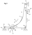
- Fig. 3 shows a dynamic flexible guide 12, which is in a closed loop is arranged with assigned drive stations.
- the flexible guide 12 is mounted on a plurality of support rollers 14.
- the Rollers can each be arranged on supports 15, 16.
- the flexible guide 12 that is designed as a closed loop moves into one through the arrow 13 indicated direction, which corresponds to the direction of movement of the signature 1.
- Of the closed loop is assigned at least one drive station 17, 23 to the flexible guide 12 to move the rollers 14 at a speed that the Speed of the signature can be adjusted so that a Speed difference between the signatures 1 and the surface of the flexible Leadership 12 can be avoided.
- the elimination of a speed difference between the signatures moved at a distance and the speed of the Guide prevents lubrication points on the signatures and ensures one smooth signature transport.
- the flexible guide 12 can have two drive stations 17 and 23 according to the invention be equipped.
- the drive station 17 is the lower end of the flexible guide 12 assigned after the latter has rotated around the roller 14, and the Drive station 23 is assigned to the upper end of flexible guide 12.
- a additional tension roller 14 can be arranged in the lower right corner, which the flexible guide 12 between the drive stations 17 and 23 spans and the shape of the flexible guide 12 on the arcuate portion of their career is not affected.
- the drive stations 17 and 23 can each comprise a pair of press rolls 18, 19, who cooperate with each other.
- the press roll 19 rotates in the direction 20 and Press roll 18 rotates in the direction 21.
- Both drive stations 17 and 23 for the flexible guide 12 are operated synchronously so that it is moved continuously.
- the material properties of the flexible guide 12 determine the degree the deformation of the flexible guide 12.
- a light, flexible material fits the The shape of the signature is lighter and a heavy, less flexible material forces it Signature to adapt to leadership more quickly.
- the material can be permeable (i.e., it can be made from a plurality of spaced strips, e.g., nylon or consist of a flexible grid) or it can be impermeable (i.e. it can Bow of a fabric-like material such as nylon).
- anyone can use this material desired width, it can also be wider than the signature or as wide as these be.
- a signature 1 can be gripped by a gripping member (not shown) on its leading edge 2 and moved by a deceleration drum (not shown) to move along the flexible guide 12 according to the present invention.
- the flexible guide 12 assumes an arcuate shape while being moved at the same speed as the signature 1.
- the impact force to which a signature received by the flexible guide 12 is exposed corresponds to an impulse force which is equal to 1 F average x ⁇ t (ie the product of an average force (F average ) multiplied by the time interval of the impact ( ⁇ t)).
- F average average force
- ⁇ t time interval of the impact
- the degree of deformation of the flexible guides 7 and 12 depends for example on the properties of the selected material for these guides.
- a design of the flexible guide 12 in a width that the width of the corresponds to the respective signature to be conveyed 1 or is wider than this and at Using an impermeable material for the touch becomes a natural one Air cushion created between the surface of the flexible guide and the signature 1.
- additional air can be blown into the area between by means of a fan 34 the signature and the guide 7 are introduced.
- the surface of the flexible guide 12 and the signature 1 so there is trapped air, so that thereby a direct contact between the surfaces of the signature 1 and the flexible Leadership 12 is avoided.
- the guide can be made of an impermeable Material that has a selected number of air holes 37, or from one permeable material.
- the air between the moving Signature 1 and the surface of the flexible guide 12 can by means of a Blower device 35 are pressed out through the permeable surface, the Blower device 35 via a selectively created guide channel 36 with a cavity communicates with the guide and the cavity except for the air holes 37 is airtight.
- Fig. 4 shows a further embodiment of the dynamic according to the invention 3, which is a liquid application station 24 and a Includes cleaning station, which are integrated into the track of the flexible guide 12.
- the liquid application station 24 has a liquid container 26 which, for. B. liquid Contains silicone 25.
- the Significant coefficient of friction By applying silicone before a signature 1 the surface of the flexible Guide 12 contacted at high speeds, the Significant coefficient of friction. At high speeds processed signatures the generated air cushion between the signature 1 and the Surface of the flexible guide 12 is not sufficient to prevent direct contact. Thus, the effects of direct contact between the signature and the flexible guide 12 minimized by reducing the coefficient of friction. This is, however, more important for a stationary flexible guide 7, as shown in FIG. 2, than for a dynamic flexible guide 12 which is driven and in which none Differences in speed occur.
- the liquid application station 24 is behind one upper drive station 23 arranged to a freshly applied, very thin To produce coating of the surface of the flexible guide 12.
- an antistatic solution within the Liquid application station 24 can be used to increase the static attraction between the two moving elements, namely the signature 1 and the to reduce flexible guidance 12.
- a cleaning station 29 is located at the lower end of the flexible guide 12, after it has passed a lower drive station 17.
- the cleaning station 29 comprises two guide rollers 30 which deform the flexible guide 12 so that one sufficient contact length is guaranteed along the surface of the flexible Guide 12 can be cleaned by means of a cleaning brush 31 or the like.
- the Cleaning brush 31 is assigned to a container 32 which is a cleaning solution contains to remove contaminants on the surface of the flexible To facilitate leadership 12.
- the present invention also discloses a method for guiding transported Products.
- the flexible guides 7 and 12, as shown in Figs. 2-4, are carried by at least one support 8, 15 and the material properties are so chosen that the flexible guides 7, 12 are deformable to the time interval of To extend the surcharge for a respective signature 1. Doing so will be strong Contact forces that occur during the collision between two moving bodies exercised and directed towards the leadership, eliminated.
- the flexible guide 12 is driven such that no speed differences between the signatures 1 and the surface the flexible guide 12 arise. Thus, shear forces are between themselves moving bodies eliminated or significantly reduced.
Landscapes
- Engineering & Computer Science (AREA)
- Mechanical Engineering (AREA)
- Feeding Of Articles By Means Other Than Belts Or Rollers (AREA)
- Discharge By Other Means (AREA)
- Separation, Sorting, Adjustment, Or Bending Of Sheets To Be Conveyed (AREA)
Abstract
Description
Die vorliegende Erfindung betrifft eine Vorrichtung zum flexiblen Führen von transportierten flachen Produkten, im besonderen von Druckprodukten, wenn diese von einem Falzapparat zu weiteren Bearbeitungsstationen befördert werden.The present invention relates to a device for flexible guidance of transported flat products, especially printed products, if these from a folder to further processing stations.
Bei herkömmlichen Auslagesystemen von Rollendruckmaschinen ist für eine plötzliche Richtungsänderung einer Signatur, die an einer ortsfesten Führung aufschlägt, eine große Aufschlagkraft erforderlich. Wenn diese Aufschlagkraft der Signatur zu heftig ist, können Schmierstellen auf deren Oberfläche entstehen oder die auf die Signatur gedruckte Farbe abgerieben werden, während diese entlang der Führung transportiert wird. Die abgeriebene Farbe kann sich wiederum an der Führung absetzen und auf eine weitere Signatur übertragen werden, wobei diese verschmiert und somit beschädigt wird.In conventional delivery systems of web printing presses is for a sudden A major change in the direction of a signature that strikes a fixed guide Impact required. If the signature's impact is too violent, there may be smudges on their surface or on the signature printed ink are rubbed off as it is transported along the guide becomes. The rubbed paint can in turn settle on the guide and on one additional signature are transmitted, which is smeared and thus damaged.
EP 0 662 439 B1 zeigt eine pneumatische Bogenführungsvorrichtung in einer Bogendruckmaschine, die entlang eines Bogenförderpfades angeordnet ist. Die pneumatische Bogenführungsvorrichtung umfaßt einen oberen Teil mit Blasluft-Öffnungen und einen ausdehnbaren unteren Teil, der umfänglich mit dem oberen Teil verbunden ist. Der obere und der untere Teil bilden einen luftundurchlässigen Hohlraum. Beide Teile bestehen aus einem flexiblen Material, wobei jedoch der untere Teil wesentlich flexibler ist als der obere Teil. Der obere Teil ist biegsam und der untere Teil ist in der Weise ausdehnbar, daß durch Blasen von Luft in den zwischen beiden Teilen gebildeten Hohlraum sich eine Luftblase bildet, die bewirkt, daß der untere Teil seine Krümmung ändert.EP 0 662 439 B1 shows a pneumatic sheet guiding device in one Sheet printing machine, which is arranged along a sheet conveying path. The Pneumatic sheet guiding device comprises an upper part with blown air openings and an expandable lower part which is circumferential with the upper part connected is. The upper and lower parts form an airtight cavity. Both parts are made of a flexible material, but the lower part is much more flexible than the upper part. The upper part is flexible and the lower part is expandable in such a way that by blowing air in between the two parts formed cavity forms an air bubble, which causes the lower part of its Curvature changes.
Bei der Übergabe von Bogenmaterial, wie z. B. Signaturen, und bei der Richtungsänderung von Signaturen während hoher Fördergeschwindigkeiten taucht jedoch das Problem auf, daß die auf die zu fördernden Signaturen ausgeübten Kontakt- und Scherkräfte einen schädigenden Effekt hervorrufen können. Die Kontaktkraft wirkt in der Richtung der Führung, während die Scherkraft in der Richtung der Bewegung der Signatur wirkt.When transferring sheet material, such as. B. signatures, and at Direction change of signatures during high conveyor speeds dips however, the problem arises that the contact and Shear forces can cause a damaging effect. The contact force works in the direction of guidance, while the shear force in the direction of movement of the Signature works.
Normalerweise steigt bei einem Aufschlag eine von einem Körper auf einen anderen ausgeübte konstante Kraft in relativ kurzer Zeit auf einen sehr hohen Wert an. Der durchschnittliche Wert (Faverage) und die Zeit (Δt), über welche die Kraft wirkt, stellen den Kraftimpuls der Signatur (d. h. Kraft gegen Zeitkurve) und somit das Bewegungsmoment der Signatur dar. Folglich ist es notwendig, den Effekt der auf eine entlang eines Pfades transportierten Signatur wirkenden Aufschlagkräfte zu reduzieren.Normally, with a serve, a constant force exerted from one body to another increases to a very high value in a relatively short time. The average value (F average ) and the time (Δt) over which the force acts represent the force impulse of the signature (ie force versus time curve) and thus the moment of movement of the signature. It is therefore necessary to measure the effect on one of a path transported signature to reduce impact forces.
Im Hinblick auf den oben beschriebenen Stand der Technik und die damit einher gehenden Nachteile ist es eine Aufgabe der vorliegenden Erfindung, eine Vorrichtung zum flexiblen Führen von transportierten Produkten einschließlich einer flexiblen Führung zum Stützen von Signaturen zu schaffen. Die flexible Führung der vorliegenden Erfindung ist fähig, sich zu verformen, um den Zeitabstand, in dem ein Aufprall der Signatur zu deren Richtungsänderung stattfindet, zu verlängern. Die Führung ist auf mindestens einer Stütze gelagert. Die Vorrichtung zum flexiblen Führen von transportierten Produkten ist besonders nützlich in Auslagekomponenten eines Falzapparates oder in Falzapparaten allgemein.With regard to the prior art described above and the associated disadvantages, it is an object of the present invention to provide a device for flexible management of transported products including a flexible one Create guidance to support signatures. The flexible management of the present Invention is able to deform to the time interval in which an impact occurs Extend signature to change direction. The leadership is on stored at least one support. The device for flexible guidance of transported products is particularly useful in delivery components of a Folders or in folders generally.
Die erfindungsgemäße Vorrichtung bietet den Vorteil, daß die auf die Signatur ausgeübte durchschnittliche Aufschlagkraft verringert werden kann, indem der Zeitabstand, in dem der Zusammenstoß zwischen der Signatur und der Führung erfolgt, verlängert wird. Somit kann der auf die Signatur wirkende Aufschlag bedeutend abgeschwächt werden, weil der Zusammenstoß der Signatur mit der Führung, wobei die Signatur ihre Richtung ändert, in einem längeren Zeitabstand stattfinden kann.The device according to the invention has the advantage that the signature applied Average impact can be reduced by the time interval in which the collision between the signature and the leadership takes place, is extended. Thus, the markup can be significantly weakened, because the collision of the signature with the leadership, the signature taking its direction changes, can take place at a longer interval.
Nach einer weiteren Ausführungsform der vorliegenden Erfindung kann die flexible Führung entweder von stationärer oder dynamischer Art sein. Beide Führungsarten können sich verformen, um beim Aufschlag der Signatur auf der Führung Aufschlagkraft zu absorbieren. Bei der stationären flexiblen Führung kann sich deren bogenförmige Länge verformen. Die Verformung der flexiblen Führung kann noch begünstigt werden, indem diese zwischen zwei Stützen gelagert wird, die jeweils auf einer anderen Ebene angeordnet sind.According to a further embodiment of the present invention, the flexible Leadership can be either stationary or dynamic. Both types of leadership can deform to impact force when the signature hits the guide to absorb. The stationary flexible guide can be curved Deform length. The deformation of the flexible guide can still be favored by placing it between two supports, each on a different level are arranged.
Gemäß vorliegender Erfindung kann eine flexible Führung eine beliebige gewünschte Form und Breite haben, sie kann auch die Breite der Signatur oder eine größere Breite aufweisen. Zwischen der Signatur und einer undurchlässigen Oberfläche der flexiblen Führung kann sich ein natürliches Luftkissen bilden. Die flexible Führung kann auch aus durchlässigem Material konstruiert sein, so daß Druckluft durch die flexible Führung geblasen werden kann, um so die Bildung eines Luftkissens zu fördern.According to the present invention, flexible guidance can be any desired Form and width, they can also be the width of the signature or a larger width exhibit. Between the signature and an impervious surface of the flexible Leadership can form a natural cushion of air. The flexible leadership can also work out permeable material to be constructed so that compressed air through the flexible guide can be blown to promote the formation of an air cushion.
Nach einem weiteren Ausführungsbeispiel der vorliegenden Erfindung ist die erfindungsgemäße Vorrichtung nicht als eine stationäre flexible Führung, sondern als eine endlose Schlaufe angeordnet, die sich in die Richtung der jeweiligen Signatur bewegt. Bei dieser Konstruktion entwickeln sich keine Scherkräfte zwischen der Signatur und der flexiblen Führung. Wenn die Geschwindigkeiten der Signatur und der dynamischen flexiblen Führung aneinander angepaßt sind, so daß keine Differenz besteht, ist eine gleichmäßigere Signaturführung erzielt, bei der Scherkräfte ausgeschlossen sind. Die dynamische flexible Führung ist als eine geschlossene Schlaufe konstruiert und kann von walzenförmigen Stützen gestützt sein, so daß eine Relativbewegung der Führung bezüglich der Stützwalzen möglich ist. Für die Bewegung der dynamischen flexiblen Führung kann dieser mindestens eine Antriebsstation zugeordnet sein. In einem Ausführungsbeispiel der Erfindung weist die Antriebsstation Preßwalzen auf, die miteinander kooperieren, indem sie die dynamische flexible Führung entlang ihres Bewegungspfades winden.According to a further embodiment of the present invention, the Device according to the invention not as a stationary flexible guide, but as an endless loop arranged in the direction of the respective signature emotional. With this construction, no shear forces develop between the signature and flexible leadership. If the speeds of the signature and the dynamic flexible guidance are adapted to each other so that no difference exists, a more even signature management is achieved with the shear forces excluded are. The dynamic flexible guide is as a closed loop constructed and can be supported by roller-shaped supports, so that a Relative movement of the guide with respect to the support rollers is possible. For the movement The dynamic flexible guide can be at least one drive station be assigned. In one embodiment of the invention, the drive station Press rolls on that cooperate with each other by providing dynamic flexible guidance wind along their path of movement.
Ferner kann die Vorrichtung und das Verfahren gemäß vorliegender Erfindung eine Flüssigkeitsauftragstation umfassen, wo eine Flüssigkeit, z. B. Silikon, aufgetragen wird, um den Reibungsfaktor zu verringern und folglich Schmierstellen zu verhindern. Es können auch antistatische Flüssigkeiten aufgetragen werden, die die statische Anziehungskraft zwischen der Führung und den Signaturen vermindern. Letztendlich kann der dynamischen flexiblen Führung eine Reinigungsstation zugeordnet sein, um Verunreinigungen von der Oberfläche der dynamischen flexiblen Führung zu entfernen und einen Farbaufbau dauerhaft zu verhindern.Furthermore, the device and the method according to the present invention can be a Liquid application station include where a liquid, e.g. B. silicone is applied, to reduce the friction factor and consequently prevent lubrication points. It Antistatic liquids can also be applied, which are static Reduce the attraction between the guide and the signatures. At long last a cleaning station can be assigned to the dynamic flexible guide in order to Remove impurities from the surface of the dynamic flexible guide and permanently prevent color build-up.
In einem weiteren Ausführungsbeispiel der vorliegenden Erfindung ist ein Verfahren für die Schaffung einer flexiblen Führung dargestellt, die von mindestens einer Stütze getragen wird und sich durch den Aufschlag einer Signatur verformen kann, so daß der Zeitraum, in dem die Richtungsänderung der Signatur stattfindet, verlängert wird und somit die auf die Signatur durchschnittlich einwirkenden Kräfte verringert werden. Die dynamische flexible Führung kann in der Weise angetrieben werden, daß die Geschwindigkeitsdifferenz zwischen der Signatur und der dynamischen flexiblen Führung minimiert ist.In a further exemplary embodiment of the present invention, a method for the creation of a flexible guide represented by at least one prop is worn and deformed by the addition of a signature, so that the Period in which the direction change of the signature takes place is extended and thus the forces acting on the signature on average are reduced. The dynamic flexible guidance can be driven in such a way that the Speed difference between the signature and the dynamic flexible guidance is minimized.
Die Merkmale der vorliegenden Erfindung werden in der folgenden Beschreibung bevorzugter Ausführungsbeispiele im Zusammenhang mit den beigefügten, nachstehend aufgeführten Zeichnungen näher erläutert.The features of the present invention will become apparent in the following description preferred embodiments in connection with the accompanying, below listed drawings explained in more detail.
Es zeigen:
- Fig. 1A und 1B
- jeweils eine perspektivische und eine Seitenansicht einer herkömmlichen ortsfesten Führung;
- Fig. 2
- eine Seitenansicht einer stationär angebrachten flexiblen Führung gemäß einem Ausführungsbeispiel der vorliegenden Erfindung;
- Fig. 3
- eine Seitenansicht einer dynamischen flexiblen Führung, die in einer geschlossenen Schlaufe angeordnet ist und zugeordnete Antriebsstationen gemäß einem Ausführungsbeispiel der vorliegenden Erfindung aufweist; und
- Fig. 4
- eine Seitenansicht einer dynamischen flexiblen Führung mit einer Flüssigkeitsauftragstation sowie einer Reinigungsstation für die Oberfläche der flexiblen Führung gemäß einem Ausführungsbeispiel der vorliegenden Erfindung.
- 1A and 1B
- a perspective and a side view of a conventional fixed guide;
- Fig. 2
- a side view of a stationary mounted flexible guide according to an embodiment of the present invention;
- Fig. 3
- a side view of a dynamic flexible guide, which is arranged in a closed loop and has associated drive stations according to an embodiment of the present invention; and
- Fig. 4
- a side view of a dynamic flexible guide with a liquid application station and a cleaning station for the surface of the flexible guide according to an embodiment of the present invention.
Die Fig. 1A und 1B zeigen eine herkömmliche stationäre Führung 4, auf der eine
Signatur 1 befördert wird. Eine jeweilige Signatur 1 weist eine Vorderkante 2 und eine
Hinterkante 3 auf und bewegt sich in die von dem Pfeil 6 angedeutete Richtung. Die
Hinterkante 3 der Signatur 1 schwingt aufgrund der zentripetalen oder Zustrebekräfte
nach außen, bis sie die stationäre Führung 4 kontaktiert. Dadurch wird jedoch die
Signatur 1 mit einer Kraft derart beaufschlagt, daß sich die Signatur 1 an die Form der
stationären Führung 4 anpaßt. Beim Aufschlag der Signatur 1 auf die stationäre
Führung 4 wird eine sehr schnell und stark ansteigende Kraft auf die Signatur 1
ausgeübt, die letztere beschädigen kann.1A and 1B show a conventional
Fig. 2 zeigt eine stationär angebrachte flexible Führung 7 gemäß einem
Ausführungsbeispiel der vorliegenden Erfindung. Eine Signatur wird mit ihrer
Vorderkante 2, die durch ein an einen von mehreren Armen einer Verzögerungstrommel
(nicht gezeigt) befestigtes Greifelement gehalten wird, in die Richtung 6 geführt. Dies
kann z. B. eine Verzögerungstrommel sein, wie sie in US 5,452,886 offenbart ist. Es
kann eine Achse, um die sich die Verzögerungstrommel dreht, gewählt werden, so daß
bei der Drehbewegung die Greifelemente einem Pfad folgen, der sich in einem
vorbestimmten Abstand von der Oberfläche der flexiblen Führung befindet. Da die
Vorderkante von dem Greifelement gehalten wird, schlägt diese nicht auf der flexiblen
Führung 7 auf, wenn die Signatur bei ihrer Bewegung in diese Richtung verlangsamt
wird. Jedoch der Körper der Signatur 1 schwingt aufgrund der Zentriptalkräfte nach
außen und schlägt auf der stationären flexiblen Führung 7 auf.Fig. 2 shows a stationary attached
Die flexible Führung 7 ist zwischen einer oberen Stütze 8 und einer unteren Stütze 9
angeordnet. Die Stützen 8 und 9 befinden sich jeweils auf verschiedenen Ebenen. Die
flexible Führung 7 begibt sich aufgrund der Schwerkraft in eine bogenförmige Position.
Die Bogenlänge zwischen den beiden Stützen 8 und 9 ist mit der Bezugsziffer 11
bezeichnet. Die flexible Führung 7 verformt sich beim Kontakt mit einer jeweiligen
Signatur 1, so daß der Signatur 1 mehr Zeit gewährt ist, in Entsprechung ihres Impulses
eine Durchschnittskraft auf die flexible Führung 7 zu übertragen (d. h., daß sich der
Zeitabstand des Aufschlags verlängert und sich somit die Durchschnittskraft für einen
gegebenen Impuls verringert). Die Form der flexiblen Führung 7, die sich zwischen den
beiden Stützen 8, 9 hängend erstreckt, kann durch Ändern der Länge der flexiblen
Führung 7 variiert werden.The
Die zwischen den beiden Stützen 8, 9 frei hängende bogenförmige Länge 11 der
Führung 7 beeinflußt die Verformung und folglich die darauf ausgeübten Kontaktkräfte.
Ferner kann der Grad der Verformung und damit der Grad der Verlängerung des
Zeitabstandes durch Wählen eines Materials für die Führung, das die geeigneten
Eigenschaften besitzt, verändert werden. Eine Führung aus einem leichteren, flexibleren
Material wird sich der Form der zu führenden Signatur 1 leichter anpassen, wohingegen
eine Führung aus einem schwereren, weniger flexiblen Material die Signatur veranlaßt,
beim Aufschlag auf die Führung 7 schneller zu reagieren.The freely hanging
Fig. 3 zeigt eine dynamische flexible Führung 12, die in einer geschlossenen Schlaufe
mit zugeordneten Antriebsstationen angeordnet ist. Bei dieser Ausführungsform der
Erfindung ist die flexible Führung 12 auf mehreren Stützwalzen 14 angebracht. Die
Walzen können jeweils auf Trägern 15, 16 angeordnet sein. Die flexible Führung 12, die
als eine geschlossene Schlaufe ausgebildet ist, bewegt sich in eine durch den Pfeil 13
angedeutete Richtung, die der Bewegungsrichtung der Signatur 1 entspricht. Der
geschlossenen Schlaufe ist mindestens eine Antriebsstation 17, 23 zugeordnet, um die
flexible Führung 12 um die Walzen 14 mit einer Geschwindigkeit zu bewegen, die der
Geschwindigkeit der Signatur angepaßt werden kann, so daß eine
Geschwindigkeitsdifferenz zwischen den Signaturen 1 und der Oberfläche der flexiblen
Führung 12 vermieden werden. Die Eliminierung einer Geschwindigkeitsdifferenz
zwischen den in einem Abstand bewegten Signaturen und der Geschwindigkeit der
Führung verhindert Schmierstellen auf den Signaturen und gewährleistet einen
reibungslosen Signaturtransport. Fig. 3 shows a dynamic
Nach einem weiteren in Fig. 3 gezeigten Ausführungsbeispiel der vorliegenden
Erfindung kann die flexible Führung 12 jeweils mit zwei Antriebsstationen 17 und 23
ausgestattet sein. Die Antriebsstation 17 ist dem unteren Ende der flexiblen Führung 12
zugeordnet, nachdem sich letztere um die Walze 14 gedreht hat, und die
Antriebsstation 23 ist dem oberen Ende der flexiblen Führung 12 zugeordnet. Eine
zusätzliche Spannwalze 14 kann in der unteren rechten Ecke angeordnet sein, die die
flexible Führung 12 zwischen den Antriebsstationen 17 und 23 spannt und die Form der
flexiblen Führung 12 auf dem bogenförmigen Abschnitt ihrer Laufbahn nicht beeinflußt.
Die Antriebsstationen 17 und 23 können jeweils ein Paar Preßwalzen 18, 19 umfassen,
die miteinander kooperieren. Die Preßwalze 19 dreht sich in die Richtung 20 und die
Preßwalze 18 dreht sich in die Richtung 21. Beide Antriebsstationen 17 und 23 für die
flexible Führung 12 werden synchron betätigt, so daß diese kontinuierlich bewegt wird.According to a further exemplary embodiment of the present shown in FIG. 3
The
Wie im Zusammenhang mit dem in Fig. 2 gezeigten Ausführungsbeispiel der Erfindung
erwähnt wurde, bestimmen die Materialeigenschaften der flexiblen Führung 12 den Grad
der Verformung der flexiblen Führung 12. Ein leichtes, flexibleres Material paßt sich der
Form der Signatur leichter an und ein schweres, weniger flexibles Material zwingt die
Signatur, sich schneller an die Führung anzupassen. Das Material kann durchlässig sein
(d. h. es kann aus mehreren voneinander beabstandeten Streifen, z. B. aus Nylon oder
aus einem flexiblen Gitter, bestehen), oder es kann undurchlässig sein (d. h. es können
Bogen eines gewebeartigen Materials, wie Nylon, sein). Das Material kann jede
gewünschte Breite haben, es kann auch breiter als die Signatur oder genauso breit wie
diese sein.As in connection with the embodiment of the invention shown in FIG. 2
was mentioned, the material properties of the
Wie oben beschrieben, kann eine Signatur 1 von einem Greifelement (nicht gezeigt) an
seiner Vorderkante 2 ergriffen und durch eine Verzögerungstrommel (nicht gezeigt)
bewegt werden, um entlang der flexiblen Führung 12 gemäß vorliegender Erfindung
bewegt zu werden. Zwischen der oberen und der unteren Stütze 15 und 16 nimmt die
flexible Führung 12 eine bogenartige Form an, während diese mit der gleichen
Geschwindigkeit wie die Signatur 1 bewegt wird. Somit treten keine nennenswerten
Geschwindigkeitsdifferenzen zwischen der bewegten Oberfläche der flexiblen
Führung 12 und der eintreffenden Signatur 1 in Erscheinung. Folglich ist aufgrund der
Reduzierung der Relativbewegung zwischen zwei Oberflächen ein Abschmieren der
Signaturen ausgeschlossen. Mit der Reduzierung der Geschwindigkeitsdifferenz
verringert sich auch wesentlich der Effekt der Scherkräfte. Beim Kontakt mit der
flexiblen Fühlung 12 entwickelt sich eine Kontaktkraft zwischen der flexiblen
Führung 12 und der jeweiligen Signatur 1, die normal auf die flexible Führung 12
gerichtet ist. Die Aufschlagkraft, welcher eine von der flexiblen Führung 12
aufgenommenen Signatur ausgesetzt ist, entspricht einer Impulskraft, die gleich
1 Faverage x Δt (d. h. das Produkt einer Durchschnittskraft (Faverage) multipliziert mit dem
Zeitabstand des Aufschlags (Δt)) ist. Um die Durchschmittskraft, der die Signatur für
einen gegebenen Impuls ausgesetzt ist, zu reduzieren, wird der Zeitabstand des
Zusammenstoßes verlängert. Dies wird durch Verformung der flexiblen Führung 12
während des Zusammenstoßens mit einer jeweiligen Signatur 1 erzielt. Die flexible
Führung 12 folgt der Form der einlaufenden Signatur 1 und nimmt diese Form an, wobei
der Zeitabstand Δt, in dem der Kontakt zwischen der Signatur und der flexiblen
Führung 12 stattfindet, verlängert wird. Somit ist die auf die Signatur 1 ausgeübte
Durchschnittskraft in bedeutendem Maße reduziert.As described above, a
Wie bereits erwähnt, hängt der Grad der Verformung der flexiblen Führungen 7 und 12
beispielsweise von den Eigenschaften des gewählten Materials für diese Führungen ab.
Bei einer Gestaltung der flexiblen Führung 12 in einer Breite, die der Breite der
jeweiligen zu befördernden Signatur 1 entspricht oder breiter als diese ist, und bei
Verwendung eines undurchlässigen Materials für die Fühlung wird ein natürliches
Luftkissen zwischen der Oberfläche der flexiblen Führung und der Signatur 1 geschaffen.
Beispielsweise kann mittels eines Gebläses 34 zusätzliche Luft in den Bereich zwischen
der Signatur und der Führung 7 eingeführt werden. Zwischen der Oberfläche der
flexiblen Führung 12 und der Signatur 1 existiert also eingeschlossene Luft, so daß
dadurch ein direkter Kontakt zwischen den Oberflächen der Signatur 1 und der flexiblen
Führung 12 vermieden wird. Der Effekt dieser zwischen der Signatur 1 und der
Oberfläche der flexiblen Führung 12 eingeschlossenen Luft wird natürlich von der
Geschwindigkeit der Signatur und den zentripetalen Kräften, die während der
Umdrehung des mit einem Arm einer Verzögerungstrommel (nicht gezeigt) oder einer
anderen geeigneten Verzögerungseinrichtung verbundenen Greifelements auf die
Signatur 1 ausgeübt werden, abhängen.As already mentioned, the degree of deformation of the
In einem weiteren Ausführungsbeispiel kann die Führung aus einem undurchlässigen
Material, das eine gewählte Anzahl von Luftlöchern 37 aufweist, oder auch aus einem
durchlässigen Material konstruiert sein. Die Luft zwischen der sich bewegenden
Signatur 1 und der Oberfläche der flexiblen Führung 12 kann mittels einer
Blaseinrichtung 35 durch die durchlässige Oberfläche hinausgepreßt werden, wobei die
Blaseinrichtung 35 über einen wählweise angelegten Leitkanal 36 mit einem Hohlraum
der Führung in Verbindung steht und der Hohlraum mit Ausnahme der Luftlöcher 37
luftdicht ist.In another embodiment, the guide can be made of an impermeable
Material that has a selected number of air holes 37, or from one
permeable material. The air between the moving
Fig. 4 zeigt ein weiteres erfindungsgemäßes Ausführungsbeispiel der dynamischen
flexiblen Führung gemäß Fig. 3, das eine Flüssigkeitsauftragstation 24 sowie eine
Reinigungsstation umfaßt, die in die Laufbahn der flexiblen Führung 12 integriert sind.
Die Flüssigkeitsauftragstation 24 weist einen Flüssigkeitsbehälter 26, der z. B. flüssiges
Silikon 25 enthält. Ein sich drehendes Flüssigkeitsauftragselement 27, z. B. eine
Tauchwalze, bringt die Flüssigkeit auf die Oberfläche der flexiblen Führung 12 auf.Fig. 4 shows a further embodiment of the dynamic according to the
Durch das Auftragen von Silikon bevor eine Signatur 1 die Oberfläche der flexiblen
Führung 12 bei hohen Geschwindigkeiten kontaktiert, verringert sich der
Reibungskoeffizient in bedeutendem Maße. Bei mit hohen Geschwindigkeiten
bearbeiteten Signaturen reicht das erzeugte Luftkissen zwischen der Signatur 1 und der
Oberfläche der flexiblen Führung 12 nicht aus, um einen direkten Kontakt zu verhindern.
Somit werden die Auswirkungen des direkten Kontakts zwischen der Signatur und der
flexiblen Führung 12 durch die Verringerung des Reibungskoeffizienten minimiert. Dies
ist jedoch wichtiger für eine stationären flexible Führung 7, wie in Fig. 2 gezeigt, als für
eine dynamische flexible Führung 12, die angetrieben wird und bei der keine
Geschwindigkeitsdifferenzen auftreten. Die Flüssigkeitsauftragstation 24 ist hinter einer
oberen Antriebsstation 23 angeordnet, um eine frisch aufgetragene, sehr dünne
Beschichtung der Oberfläche der flexiblen Führung 12 zu erzeugen. Zusätzlich zu
flüssigem Silikon oder einer Silikonlösung kann eine antistatische Lösung innerhalb der
Flüssigkeitsauftragstation 24 verwendet werden, um die statische Anziehungskraft
zwischen den beiden sich bewegenden Elementen, nämlich der Signatur 1 und der
flexiblen Führung 12 zu verringern.By applying silicone before a
Eine Reinigungsstation 29 befindet sich am unteren Ende der flexiblen Führung 12,
nachdem diese eine untere Antriebsstation 17 passiert hat. Die Reinigungsstation 29
umfaßt zwei Führungswalzen 30, welche die flexible Führung 12 verformen, so daß eine
ausreichende Kontaktlänge gewährleistet ist, entlang der die Oberfläche der flexiblen
Führung 12 mittels einer Reinigungsbürste 31 o. ä. gereinigt werden kann. Die
Reinigungsbürste 31 ist einem Behälter 32 zugeordnet, der eine Reinigungslösung
enthält, um die Beseitigung von Verunreinigungen auf der Oberfläche der flexiblen
Führung 12 zu erleichtern.A cleaning
Die vorliegende Erfindung offenbart auch ein Verfahren zum Führen transportierter
Produkte. Die flexiblen Führungen 7 und 12, wie sie in den Fig. 2-4 gezeigt sind,
werden von mindestens einer Stütze 8, 15 getragen und die Materialeigenschaften sind so
gewählt, daß die flexiblen Führungen 7, 12 verformbar sind, um den Zeitabstands des
Aufschlags bezüglich einer jeweiligen Signatur 1 zu verlängern. Dabei werden starke
Kontaktkräfte, die beim Zusammenstoß zwischen zwei sich bewegenden Körpern
ausgeübt und normal auf die Führung gerichtet werden, eliminiert. Gemäß dem
Verfahren der vorliegenden Erfindung wird die flexible Führung 12 derart angetrieben,
daß keine Geschwindigkeitsdifferenzen zwischen den Signaturen 1 und der Oberfläche
der flexiblen Führung 12 entstehen. Somit sind auch Scherkräfte zwischen zwei sich
bewegenden Körpern beseitigt oder wesentlich reduziert. The present invention also discloses a method for guiding transported
Products. The
- 11
- Signatursignature
- 22nd
- Vorderkante der SignaturFront edge of the signature
- 33rd
- Hinterkante der SignaturTrailing edge of the signature
- 44th
- stationäre Führungstationary leadership
- 66
- Pfeilarrow
- 77
- stationäre flexible Führungstationary flexible guidance
- 88th
- Stützesupport
- 99
- Stützesupport
- 1111
-
bogenförmige Länge der Führung 7arcuate length of the
guide 7 - 1212th
- dynamische flexible Führungdynamic flexible leadership
- 1313
- RichtungspfeilDirectional arrow
- 1414
- Stützwalzen, SpannwalzeBack-up rolls, tensioning roll
- 1515
- Trägercarrier
- 1616
- Trägercarrier
- 1717th
- Antriebsstation (Fig. 3)Drive station (Fig. 3)
- 1818th
- PreßwalzePress roll
- 1919th
- PreßwalzePress roll
- 2020th
- Drehrichtung der Preßwalze 19Direction of rotation of the press roller 19th
- 2121
-
Drehrichtung der Preßwalze 20Direction of rotation of the
press roller 20 - 2323
- AntriebsstationDrive station
- 2424th
- FlüssigkeitsauftragstationLiquid application station
- 2525th
- flüssiges Silikonliquid silicone
- 2626
- FlüssigkeitsbehälterLiquid container
- 2727
- TauchwalzeDipping roller
- 2929
- ReinigungsstationCleaning station
- 3030th
- FührungswalzenGuide rollers
- 3131
- ReinigungsbürsteCleaning brush
- 3232
- Reinigungslösungsbehälter Cleaning solution container
- 3434
- Gebläsefan
- 3535
- BlaseinrichtungBlowing device
- 3636
- LeitkanalLead channel
- 3737
- LuftlöcherAir holes
Claims (21)
wobei die flexible Führung (7, 12) während eines Zusammenstoßes zwischen sich und dem transportierten Produkt (1) verformbar ist, um einen Zeitabstand, in dem die flexible Führung (7, 12) mit dem transportierten Produkt (1) in Kontakt ist, zu verlängern, und wobei die flexible Führung (7, 12) durch mindestens eine Stütze (8, 15) gestützt wird.Device for flexibly guiding transported products, with a flexible guide (7, 12) which supports a transported product (1),
wherein the flexible guide (7, 12) is deformable during a collision between itself and the transported product (1) by a time interval in which the flexible guide (7, 12) is in contact with the transported product (1) extend, and wherein the flexible guide (7, 12) is supported by at least one support (8, 15).
dadurch gekennzeichnet,
daß die flexible Führung (7, 12) eine stationäre Führung ist.Flexible guiding device according to claim 1,
characterized,
that the flexible guide (7, 12) is a stationary guide.
dadurch gekennzeichnet,
daß die flexible Führung (7, 12) eine sich bewegende Führung ist.Flexible guiding device according to claim 1,
characterized,
that the flexible guide (7, 12) is a moving guide.
dadurch gekennzeichnet,
daß für die Verformung der flexiblen Führung (7) eine Länge derselben gewählt wird.Flexible guiding device according to claim 2,
characterized,
that a length of the same is chosen for the deformation of the flexible guide (7).
dadurch gekennzeichnet,
daß für die Verformung der flexiblen Führung (7) eine bogenförmige Länge (11) derselben gewählt wird. Flexible guiding device according to claim 2,
characterized,
that an arcuate length (11) of the same is chosen for the deformation of the flexible guide (7).
dadurch gekennzeichnet,
daß die flexible Führung (7) zwischen Stützen (8, 9) verformbar angebracht ist.Flexible guiding device according to claim 2,
characterized,
that the flexible guide (7) between supports (8, 9) is deformably attached.
dadurch gekennzeichnet,
daß die flexible Führung (7, 12) eine mit der Breite des transportierten Produktes (1) identische Breite aufweist oder breiter als dieses ist, so daß sich ein Luftkissen zwischen der undurchlässigen Oberfläche der Führung (7, 12) und dem transportierten Produkt (1) bilden kann.Flexible guiding device according to claim 1,
characterized,
that the flexible guide (7, 12) has an identical width to or wider than the width of the transported product (1), so that there is an air cushion between the impermeable surface of the guide (7, 12) and the transported product (1 ) can form.
dadurch gekennzeichnet,
daß die flexible Führung (7, 12) durchlässig ist, so daß mittels Druckluft ein Luftkissen zwischen der durchlässigen Führungsfläche (7, 12) und dem transportierten Produkt (1) gebildet werden kann.Flexible guiding device according to claim 1,
characterized,
that the flexible guide (7, 12) is permeable, so that an air cushion can be formed between the permeable guide surface (7, 12) and the transported product (1) by means of compressed air.
dadurch gekennzeichnet,
daß die flexible Führung (12) eine endlose Schlaufe ist, die sich in der Richtung (6) des transportierten Produktes (1) bewegt.Flexible guiding device according to claim 3,
characterized,
that the flexible guide (12) is an endless loop that moves in the direction (6) of the transported product (1).
dadurch gekennzeichnet,
daß die flexible Führung (12) als endlose Schlaufe mit einer Oberflächengeschwindigkeit angetrieben wird, die in etwa die Geschwindigkeit des transportierten Produktes (1) ist.Flexible guiding device according to claim 3,
characterized,
that the flexible guide (12) is driven as an endless loop with a surface speed that is approximately the speed of the transported product (1).
dadurch gekennzeichnet,
daß die flexible Führung (12) eine geschlossene Schlaufe und auf als Walzen (14) ausgebildeten Stützen (15, 16) angebracht ist.Flexible guiding device according to claim 3,
characterized,
that the flexible guide (12) has a closed loop and is mounted on supports (15, 16) designed as rollers (14).
dadurch gekennzeichnet,
daß die flexible Führung (12) von mindestens einer Antriebsstation (17, 23) angetrieben wird.Flexible guiding device according to claim 3,
characterized,
that the flexible guide (12) is driven by at least one drive station (17, 23).
dadurch gekennzeichnet,
daß die mindestens eine Antriebsstation (17, 23) miteinander kooperierende Preßwalzen (20, 21) umfaßt, durch die die flexible Führung (12) in die Bewegungsrichtung des transportierten Produktes (1) gewunden wird.Flexible guiding device according to claim 12,
characterized,
that the at least one drive station (17, 23) comprises cooperating press rolls (20, 21) through which the flexible guide (12) is wound in the direction of movement of the transported product (1).
dadurch gekennzeichnet,
daß die flexible Führung (12) eine Flüssigkeitsauftragstation (24) passiert, durch die eine Flüssigkeit auf die Oberfläche der flexiblen Führung (12) aufgetragen wird.Flexible guiding device according to claim 3,
characterized,
that the flexible guide (12) passes a liquid application station (24) through which a liquid is applied to the surface of the flexible guide (12).
dadurch gekennzeichnet,
daß die flexible Führung (12) eine Reinigungsstation (29) passiert, durch die Verunreinigungen von der Oberfläche der flexiblen Führung (12) entfernt werden.Flexible guiding device according to claim 3,
characterized,
that the flexible guide (12) passes a cleaning station (29) through which contaminants are removed from the surface of the flexible guide (12).
dadurch gekennzeichnet,
daß die aufgetragene Flüssigkeit eine Silikonlösung ist.Flexible guiding device according to claim 14,
characterized,
that the liquid applied is a silicone solution.
dadurch gekennzeichnet,
daß die aufgetragene Flüssigkeit eine antistatische Lösung ist.Flexible guiding device according to claim 14,
characterized,
that the liquid applied is an antistatic solution.
dadurch gekennzeichnet,
daß das transportierte Produkt (1) eine bedruckte Signatur ist.Flexible guiding device according to claim 14,
characterized,
that the transported product (1) is a printed signature.
Stützen einer flexiblen Führung durch mindestens eine Stütze; Befördern des transportieren Produktes zur flexiblen Führung; und Verlängern des Zeitabstandes für die Richtungsänderung des transportierten Produktes mittels einer Verformung der flexiblen Führung.Method for carrying a transported product, comprising the following steps:
Supporting a flexible guide by at least one support; Transporting the transported product for flexible guidance; and extending the time interval for the change in direction of the transported product by means of a deformation of the flexible guide.
dadurch gekennzeichnet,
daß die flexible Führung in einer geschlossenen Schlaufe bewegbar ist und derart angetrieben wird, daß eine Geschwindigkeitsdifferenz zwischen dem transportierten Produkt und der flexiblen Führung minimiert ist.Method for guiding a transported product according to claim 20,
characterized,
that the flexible guide is movable in a closed loop and driven in such a way that a speed difference between the transported product and the flexible guide is minimized.
Applications Claiming Priority (2)
| Application Number | Priority Date | Filing Date | Title |
|---|---|---|---|
| US42009 | 1998-03-13 | ||
| US09/042,009 US6145649A (en) | 1998-03-13 | 1998-03-13 | Device for flexible guiding of conveyed products |
Publications (2)
| Publication Number | Publication Date |
|---|---|
| EP0941956A1 true EP0941956A1 (en) | 1999-09-15 |
| EP0941956B1 EP0941956B1 (en) | 2002-12-04 |
Family
ID=21919563
Family Applications (1)
| Application Number | Title | Priority Date | Filing Date |
|---|---|---|---|
| EP99101555A Expired - Lifetime EP0941956B1 (en) | 1998-03-13 | 1999-02-01 | Device for flexible guiding of moved products |
Country Status (3)
| Country | Link |
|---|---|
| US (1) | US6145649A (en) |
| EP (1) | EP0941956B1 (en) |
| DE (2) | DE59903614D1 (en) |
Cited By (1)
| Publication number | Priority date | Publication date | Assignee | Title |
|---|---|---|---|---|
| EP1095770A1 (en) * | 1999-10-30 | 2001-05-02 | MAN Roland Druckmaschinen AG | Cleaning apparatus for a sheet guiding device of a rotary printing machine |
Families Citing this family (3)
| Publication number | Priority date | Publication date | Assignee | Title |
|---|---|---|---|---|
| DE19735051C2 (en) * | 1997-08-13 | 1999-06-17 | Koenig & Bauer Ag | Device for splitting a stream of signatures |
| US6874615B2 (en) * | 2003-06-06 | 2005-04-05 | David M Fallas | Conveyor chute |
| WO2020148873A1 (en) * | 2019-01-17 | 2020-07-23 | 富士通フロンテック株式会社 | Paper sheet handling device |
Citations (5)
| Publication number | Priority date | Publication date | Assignee | Title |
|---|---|---|---|---|
| JPS5721164A (en) * | 1980-07-14 | 1982-02-03 | Hitachi Ltd | Facsimile device |
| EP0059873A1 (en) * | 1981-03-07 | 1982-09-15 | M.A.N.-ROLAND Druckmaschinen Aktiengesellschaft | Device for stripping printed products of the delivery fans of a folding apparatus |
| DE3513353A1 (en) * | 1984-06-27 | 1986-01-09 | VEB Kombinat Polygraph "Werner Lamberz" Leipzig, DDR 7050 Leipzig | Stack delivery for folded sheets stacked on edge |
| EP0490272A1 (en) * | 1990-12-13 | 1992-06-17 | EASTMAN KODAK COMPANY (a New Jersey corporation) | Guiding device for stacking sheets of paper |
| EP0662439A1 (en) * | 1993-12-23 | 1995-07-12 | Kba-Planeta Ag | Pneumatic sheet guiding device |
Family Cites Families (9)
| Publication number | Priority date | Publication date | Assignee | Title |
|---|---|---|---|---|
| FR1395539A (en) * | 1963-03-29 | 1965-04-16 | Cefilac | Device for coating with lubricating powder, before spinning or drilling, hot billets of any shape |
| US3416679A (en) * | 1967-01-16 | 1968-12-17 | Stobb Inc | Signature feeder |
| US4227875A (en) * | 1978-09-12 | 1980-10-14 | Calcimatic International Limited | Rotary hearth for calcining kiln |
| DE4041692C1 (en) * | 1990-12-24 | 1992-04-02 | Johann 8391 Sonnen De Binder | |
| US5452886A (en) * | 1993-08-09 | 1995-09-26 | Heidelberger Druckmaschinen Ag | Device for slowing down signatures in a folding machine |
| US5355992A (en) * | 1993-10-15 | 1994-10-18 | Utility Technical Services, Inc. | Belt cleaning apparatus |
| US5544733A (en) * | 1994-09-30 | 1996-08-13 | Jervis B. Webb Company | Wheeled luggage tipper |
| US5613594A (en) * | 1995-08-10 | 1997-03-25 | Stein, Inc. | Conveyor belt treatment apparatus |
| US5641263A (en) * | 1996-01-19 | 1997-06-24 | Vulcan Tool Corporation | Bundle unscrambler |
-
1998
- 1998-03-13 US US09/042,009 patent/US6145649A/en not_active Expired - Fee Related
-
1999
- 1999-02-01 EP EP99101555A patent/EP0941956B1/en not_active Expired - Lifetime
- 1999-02-01 DE DE59903614T patent/DE59903614D1/en not_active Expired - Fee Related
- 1999-02-01 DE DE19903888A patent/DE19903888A1/en not_active Withdrawn
Patent Citations (5)
| Publication number | Priority date | Publication date | Assignee | Title |
|---|---|---|---|---|
| JPS5721164A (en) * | 1980-07-14 | 1982-02-03 | Hitachi Ltd | Facsimile device |
| EP0059873A1 (en) * | 1981-03-07 | 1982-09-15 | M.A.N.-ROLAND Druckmaschinen Aktiengesellschaft | Device for stripping printed products of the delivery fans of a folding apparatus |
| DE3513353A1 (en) * | 1984-06-27 | 1986-01-09 | VEB Kombinat Polygraph "Werner Lamberz" Leipzig, DDR 7050 Leipzig | Stack delivery for folded sheets stacked on edge |
| EP0490272A1 (en) * | 1990-12-13 | 1992-06-17 | EASTMAN KODAK COMPANY (a New Jersey corporation) | Guiding device for stacking sheets of paper |
| EP0662439A1 (en) * | 1993-12-23 | 1995-07-12 | Kba-Planeta Ag | Pneumatic sheet guiding device |
Non-Patent Citations (1)
| Title |
|---|
| PATENT ABSTRACTS OF JAPAN vol. 006, no. 087 (E - 108) 25 May 1982 (1982-05-25) * |
Cited By (1)
| Publication number | Priority date | Publication date | Assignee | Title |
|---|---|---|---|---|
| EP1095770A1 (en) * | 1999-10-30 | 2001-05-02 | MAN Roland Druckmaschinen AG | Cleaning apparatus for a sheet guiding device of a rotary printing machine |
Also Published As
| Publication number | Publication date |
|---|---|
| DE19903888A1 (en) | 1999-09-16 |
| DE59903614D1 (en) | 2003-01-16 |
| US6145649A (en) | 2000-11-14 |
| EP0941956B1 (en) | 2002-12-04 |
Similar Documents
| Publication | Publication Date | Title |
|---|---|---|
| DE2552998C2 (en) | Sheet delivery for rotary printing machines | |
| DE1761077A1 (en) | Device for pressing flexible surfaces produced in a continuous flow | |
| DE102005016745A1 (en) | Method and device for depositing a flexible material web | |
| DE3035495A1 (en) | BRANCHING FOR A SHED FLOW | |
| DE19641485A1 (en) | Device and method for braking flat products | |
| DE3128917C2 (en) | ||
| EP0579057A1 (en) | Device for turning a paper sheet in a conveying track | |
| EP0941956B1 (en) | Device for flexible guiding of moved products | |
| DE202016102026U1 (en) | Device for printing a package | |
| DE2232610C2 (en) | Chain device to a conveyor system for paper processing companies | |
| DE19856372A1 (en) | Conveyor with frame in which are cylindrical rollers | |
| DE10232215A1 (en) | Conveyor system for transport and outward transfer of flat objects with pressure rollers above conveyor modules applying pressure to carried objects during conveyor pivot movement | |
| DE19541278C2 (en) | Stacking device for card-shaped goods | |
| DE2420165A1 (en) | PAPER TRANSPORT EQUIPMENT | |
| DE3034674C2 (en) | Winding roll carrier | |
| DE60318739T2 (en) | METHOD AND DEVICE FOR HANDLING OF ROLLERS | |
| EP3305691A1 (en) | Conveying system with guide device | |
| EP0709326A1 (en) | Method and device for marking folded printed produkts on an inner page | |
| EP0283834B1 (en) | Device to attach a staple with a strip material to a leading strip | |
| DE2944958A1 (en) | DEVICE FOR REMOVING AIR FROM THE SPACE BETWEEN A ROTATING ROLE OR. ROLLER AND THIS APPROACHING OR ON THIS RAILWAY | |
| DE3937044A1 (en) | DEVICE FOR APPLYING COVER SHEETS ON STACK OF SHEETS | |
| CH715936A1 (en) | Method for unloading transport goods from a laterally open transport bag which, while hanging on a carriage, conveys the transport goods along a running rail in a conveying direction. | |
| DE3725833A1 (en) | DEVICE FOR APPLYING ADHESIVE TO LEAF-SHAPED PACKAGING MATERIAL | |
| DE4022411C2 (en) | Device for transporting flat workpieces | |
| CH673636A5 (en) |
Legal Events
| Date | Code | Title | Description |
|---|---|---|---|
| PUAI | Public reference made under article 153(3) epc to a published international application that has entered the european phase |
Free format text: ORIGINAL CODE: 0009012 |
|
| AK | Designated contracting states |
Kind code of ref document: A1 Designated state(s): CH DE FR GB IT LI NL |
|
| AX | Request for extension of the european patent |
Free format text: AL;LT;LV;MK;RO;SI |
|
| 17P | Request for examination filed |
Effective date: 19990915 |
|
| AKX | Designation fees paid |
Free format text: CH DE FR GB IT LI NL |
|
| 17Q | First examination report despatched |
Effective date: 20010528 |
|
| GRAG | Despatch of communication of intention to grant |
Free format text: ORIGINAL CODE: EPIDOS AGRA |
|
| GRAG | Despatch of communication of intention to grant |
Free format text: ORIGINAL CODE: EPIDOS AGRA |
|
| GRAH | Despatch of communication of intention to grant a patent |
Free format text: ORIGINAL CODE: EPIDOS IGRA |
|
| GRAH | Despatch of communication of intention to grant a patent |
Free format text: ORIGINAL CODE: EPIDOS IGRA |
|
| GRAA | (expected) grant |
Free format text: ORIGINAL CODE: 0009210 |
|
| AK | Designated contracting states |
Kind code of ref document: B1 Designated state(s): CH DE FR GB IT LI NL |
|
| PG25 | Lapsed in a contracting state [announced via postgrant information from national office to epo] |
Ref country code: GB Free format text: LAPSE BECAUSE OF FAILURE TO SUBMIT A TRANSLATION OF THE DESCRIPTION OR TO PAY THE FEE WITHIN THE PRESCRIBED TIME-LIMIT Effective date: 20021204 Ref country code: FR Free format text: LAPSE BECAUSE OF FAILURE TO SUBMIT A TRANSLATION OF THE DESCRIPTION OR TO PAY THE FEE WITHIN THE PRESCRIBED TIME-LIMIT Effective date: 20021204 |
|
| REG | Reference to a national code |
Ref country code: GB Ref legal event code: FG4D Free format text: NOT ENGLISH |
|
| REG | Reference to a national code |
Ref country code: CH Ref legal event code: EP |
|
| REF | Corresponds to: |
Ref document number: 59903614 Country of ref document: DE Date of ref document: 20030116 |
|
| PGFP | Annual fee paid to national office [announced via postgrant information from national office to epo] |
Ref country code: NL Payment date: 20030224 Year of fee payment: 5 |
|
| PGFP | Annual fee paid to national office [announced via postgrant information from national office to epo] |
Ref country code: CH Payment date: 20030304 Year of fee payment: 5 |
|
| PGFP | Annual fee paid to national office [announced via postgrant information from national office to epo] |
Ref country code: DE Payment date: 20030306 Year of fee payment: 5 |
|
| GBV | Gb: ep patent (uk) treated as always having been void in accordance with gb section 77(7)/1977 [no translation filed] |
Effective date: 20021204 |
|
| PLBE | No opposition filed within time limit |
Free format text: ORIGINAL CODE: 0009261 |
|
| STAA | Information on the status of an ep patent application or granted ep patent |
Free format text: STATUS: NO OPPOSITION FILED WITHIN TIME LIMIT |
|
| EN | Fr: translation not filed | ||
| 26N | No opposition filed |
Effective date: 20030905 |
|
| PG25 | Lapsed in a contracting state [announced via postgrant information from national office to epo] |
Ref country code: LI Free format text: LAPSE BECAUSE OF NON-PAYMENT OF DUE FEES Effective date: 20040229 Ref country code: CH Free format text: LAPSE BECAUSE OF NON-PAYMENT OF DUE FEES Effective date: 20040229 |
|
| PG25 | Lapsed in a contracting state [announced via postgrant information from national office to epo] |
Ref country code: NL Free format text: LAPSE BECAUSE OF NON-PAYMENT OF DUE FEES Effective date: 20040901 Ref country code: DE Free format text: LAPSE BECAUSE OF NON-PAYMENT OF DUE FEES Effective date: 20040901 |
|
| REG | Reference to a national code |
Ref country code: CH Ref legal event code: PL |
|
| NLV4 | Nl: lapsed or anulled due to non-payment of the annual fee |
Effective date: 20040901 |
|
| PG25 | Lapsed in a contracting state [announced via postgrant information from national office to epo] |
Ref country code: IT Free format text: LAPSE BECAUSE OF NON-PAYMENT OF DUE FEES Effective date: 20050201 |