EP0941435B1 - Diaphragm valve - Google Patents
Diaphragm valve Download PDFInfo
- Publication number
- EP0941435B1 EP0941435B1 EP98906044A EP98906044A EP0941435B1 EP 0941435 B1 EP0941435 B1 EP 0941435B1 EP 98906044 A EP98906044 A EP 98906044A EP 98906044 A EP98906044 A EP 98906044A EP 0941435 B1 EP0941435 B1 EP 0941435B1
- Authority
- EP
- European Patent Office
- Prior art keywords
- diaphragm
- corner
- generally flat
- bodies
- seal
- Prior art date
- Legal status (The legal status is an assumption and is not a legal conclusion. Google has not performed a legal analysis and makes no representation as to the accuracy of the status listed.)
- Expired - Lifetime
Links
- 230000002093 peripheral effect Effects 0.000 claims description 14
- 239000012530 fluid Substances 0.000 claims description 12
- 239000000463 material Substances 0.000 claims description 9
- 238000000034 method Methods 0.000 claims description 5
- 229910001220 stainless steel Inorganic materials 0.000 claims description 4
- 239000010935 stainless steel Substances 0.000 claims description 4
- 125000004122 cyclic group Chemical group 0.000 claims description 3
- 238000005452 bending Methods 0.000 claims description 2
- OKTJSMMVPCPJKN-UHFFFAOYSA-N Carbon Chemical compound [C] OKTJSMMVPCPJKN-UHFFFAOYSA-N 0.000 claims 1
- 229910052799 carbon Inorganic materials 0.000 claims 1
- 238000007789 sealing Methods 0.000 description 12
- 230000004323 axial length Effects 0.000 description 4
- 238000010276 construction Methods 0.000 description 2
- 239000002184 metal Substances 0.000 description 2
- 229920002493 poly(chlorotrifluoroethylene) Polymers 0.000 description 2
- 239000005023 polychlorotrifluoroethylene (PCTFE) polymer Substances 0.000 description 2
- 230000008569 process Effects 0.000 description 2
- 230000009471 action Effects 0.000 description 1
- 230000008859 change Effects 0.000 description 1
- 230000002860 competitive effect Effects 0.000 description 1
- 230000006835 compression Effects 0.000 description 1
- 238000007906 compression Methods 0.000 description 1
- 238000011109 contamination Methods 0.000 description 1
- 238000002788 crimping Methods 0.000 description 1
- 230000001351 cycling effect Effects 0.000 description 1
- 230000001419 dependent effect Effects 0.000 description 1
- 230000000694 effects Effects 0.000 description 1
- 239000007788 liquid Substances 0.000 description 1
- 239000000314 lubricant Substances 0.000 description 1
- 230000001050 lubricating effect Effects 0.000 description 1
- 238000012986 modification Methods 0.000 description 1
- 230000004048 modification Effects 0.000 description 1
- 230000036961 partial effect Effects 0.000 description 1
- 239000004033 plastic Substances 0.000 description 1
- -1 polychlorotrifluoroethylene Polymers 0.000 description 1
- 238000001556 precipitation Methods 0.000 description 1
- 239000012858 resilient material Substances 0.000 description 1
- 230000000717 retained effect Effects 0.000 description 1
- 238000004513 sizing Methods 0.000 description 1
- 239000007787 solid Substances 0.000 description 1
- 230000007704 transition Effects 0.000 description 1
Images





Classifications
-
- F—MECHANICAL ENGINEERING; LIGHTING; HEATING; WEAPONS; BLASTING
- F16—ENGINEERING ELEMENTS AND UNITS; GENERAL MEASURES FOR PRODUCING AND MAINTAINING EFFECTIVE FUNCTIONING OF MACHINES OR INSTALLATIONS; THERMAL INSULATION IN GENERAL
- F16K—VALVES; TAPS; COCKS; ACTUATING-FLOATS; DEVICES FOR VENTING OR AERATING
- F16K7/00—Diaphragm valves or cut-off apparatus, e.g. with a member deformed, but not moved bodily, to close the passage ; Pinch valves
-
- F—MECHANICAL ENGINEERING; LIGHTING; HEATING; WEAPONS; BLASTING
- F16—ENGINEERING ELEMENTS AND UNITS; GENERAL MEASURES FOR PRODUCING AND MAINTAINING EFFECTIVE FUNCTIONING OF MACHINES OR INSTALLATIONS; THERMAL INSULATION IN GENERAL
- F16K—VALVES; TAPS; COCKS; ACTUATING-FLOATS; DEVICES FOR VENTING OR AERATING
- F16K7/00—Diaphragm valves or cut-off apparatus, e.g. with a member deformed, but not moved bodily, to close the passage ; Pinch valves
- F16K7/12—Diaphragm valves or cut-off apparatus, e.g. with a member deformed, but not moved bodily, to close the passage ; Pinch valves with flat, dished, or bowl-shaped diaphragm
- F16K7/14—Diaphragm valves or cut-off apparatus, e.g. with a member deformed, but not moved bodily, to close the passage ; Pinch valves with flat, dished, or bowl-shaped diaphragm arranged to be deformed against a flat seat
- F16K7/16—Diaphragm valves or cut-off apparatus, e.g. with a member deformed, but not moved bodily, to close the passage ; Pinch valves with flat, dished, or bowl-shaped diaphragm arranged to be deformed against a flat seat the diaphragm being mechanically actuated, e.g. by screw-spindle or cam
-
- F—MECHANICAL ENGINEERING; LIGHTING; HEATING; WEAPONS; BLASTING
- F16—ENGINEERING ELEMENTS AND UNITS; GENERAL MEASURES FOR PRODUCING AND MAINTAINING EFFECTIVE FUNCTIONING OF MACHINES OR INSTALLATIONS; THERMAL INSULATION IN GENERAL
- F16K—VALVES; TAPS; COCKS; ACTUATING-FLOATS; DEVICES FOR VENTING OR AERATING
- F16K41/00—Spindle sealings
- F16K41/10—Spindle sealings with diaphragm, e.g. shaped as bellows or tube
- F16K41/12—Spindle sealings with diaphragm, e.g. shaped as bellows or tube with approximately flat diaphragm
-
- Y—GENERAL TAGGING OF NEW TECHNOLOGICAL DEVELOPMENTS; GENERAL TAGGING OF CROSS-SECTIONAL TECHNOLOGIES SPANNING OVER SEVERAL SECTIONS OF THE IPC; TECHNICAL SUBJECTS COVERED BY FORMER USPC CROSS-REFERENCE ART COLLECTIONS [XRACs] AND DIGESTS
- Y10—TECHNICAL SUBJECTS COVERED BY FORMER USPC
- Y10T—TECHNICAL SUBJECTS COVERED BY FORMER US CLASSIFICATION
- Y10T137/00—Fluid handling
- Y10T137/6198—Non-valving motion of the valve or valve seat
- Y10T137/6253—Rotary motion of a reciprocating valve
-
- Y—GENERAL TAGGING OF NEW TECHNOLOGICAL DEVELOPMENTS; GENERAL TAGGING OF CROSS-SECTIONAL TECHNOLOGIES SPANNING OVER SEVERAL SECTIONS OF THE IPC; TECHNICAL SUBJECTS COVERED BY FORMER USPC CROSS-REFERENCE ART COLLECTIONS [XRACs] AND DIGESTS
- Y10—TECHNICAL SUBJECTS COVERED BY FORMER USPC
- Y10T—TECHNICAL SUBJECTS COVERED BY FORMER US CLASSIFICATION
- Y10T137/00—Fluid handling
- Y10T137/6851—With casing, support, protector or static constructional installations
- Y10T137/6966—Static constructional installations
- Y10T137/6991—Ground supporting enclosure
- Y10T137/6995—Valve and meter wells
- Y10T137/6999—With means to center well on valve
Definitions
- the subject invention is directed to a high flow diaphragm valve of the general type shown in U.S. Patent Nos. 4,671,490; 4,732,363; and, 4,750,709. More particularly, the invention is directed to a diaphragm valve having an improved valve seat arrangement and an improved body seal using a single clamp and corner arrangement.
- Diaphragm valves are generally known and include a body seal arrangement and a valve seat arrangement.
- the body seal typically is achieved at or near the outer peripheral area of the diaphragm by clamping and compressing the diaphragm between facing surfaces of the valve body. Imperfections in the body surfaces and diaphragm surface, however, can require very high compression of the diaphragm to achieve a satisfactory seal. Harder materials for the diaphragm exacerbate the body seal problem at the clamping surfaces.
- a valve seat is used to seal off an inlet and outlet passageway by engaging with the diaphragm.
- Prior designs tend to have large surface areas of the seat exposed to the fluid, thus providing possible leak paths and contamination.
- Valve seat surfaces can be pre-formed with specific contours to improve sealing, but such steps tend to be time consuming and thus more expensive.
- the clamping sequence is as follows.
- the corner 26c deflects and bends the outer peripheral portion 28a of the diaphragm downward and over the corner 32 of the collar 30 (see FIGURE 5A).
- the flat 26a then begins clamping the top surface of the diaphragm 28 against the top planar surface 30a of the collar 30 ((preferably but not necessarily the flat 26a is generally parallel to the flat 30a when the bonnet and body are clamped together), while the corner 26c continues acting on the diaphragm peripheral portion 28a thus bending and crimping the diaphragm 28 around the corner 32.
- the force applied during this make-up procedure is sufficient to deform or yield the diaphragm 28 and the corner 32 to create a primary body seal there between.
- the deformation or yielding of the corner 32 and the diaphragm to form the primary seal is controlled by proper sizing of the corner 26c diameter and hardness, the corner 32 diameter, the length of the cylindrical wall 26b and the diaphragm 28 thickness. It is preferred but again not required that the deformation or yielding occur primarily at the corner 32 and the diaphragm in order to produce a good primary seal; therefore the bonnet 26 can be made of a harder material than the collar 30.
- a suitable material is 17-4PH (precipitation hardened) stainless steel although this is but one example of stainless steel and other materials that are well known to those skilled in the art.
- the primary seal corner 32 deformation is limited when the diaphragm 28 is clamped between the flat planar surfaces 26a and 30a, which clamping produces a secondary seal between the bottom surface of the diaphragm 28 and the top planar surface 30a of the collar 30. This secondary seal and clamping helps reduce or eliminate entrapment areas.
- the radial inner edge 30b of the collar 30, and the clamping force applied to the diaphragm 28 radially inward from the corner 32 primary seal area also operate to reduce stress applied to the primary seal under cyclic operation of the diaphragm 28 by acting as pivot points for the diaphragm 28 as the diaphragm cycles up and down. These pivot points are radially spaced inward of the primary seal and thereby reduce stresses applied to the primary seal area during such diaphragm movement.
- the described body seal design significantly reduces the interior space required to sealingly clamp the diaphragm 28 within the valve, thus freeing more internal space to increase fluid flow.
- the clamping forces necessary to drive the peripheral edge of the bonnet into sealing engagement with the diaphragm assembly 28 and produce the necessary sealing and clamping about the peripheral edge of the diaphragm is generated by the bonnet nut 24 being threadedly engaged with the body and suitably driven downwardly.
- the diaphragm 28 preferably has a preformed convex shape as illustrated in FIGURE 1 so that in its normal, non-deflected position, it extends above the outlet 16 from passage 14.
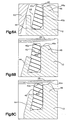
- the resilient seat ring 40 has the normal non-deformed configuration shown in FIGURE 6A and is formed from any suitable resilient material such as PCTFE (polychlorotrifluoroethylene) or any of the materials suggested in the above-identified U.S. patents depending upon the operating environment and conditions.
- PCTFE polychlorotrifluoroethylene
- This staking process causes the upper surface 40a of the seat 40 to become slightly concave to more closely match or conform with the contour of the diaphragm 28 lower surface (as viewed in FIGURE 6B) during shutoff.
- the diaphragms can be deflected downwardly during the first cycle and they generally follow the contour of the lower end of the operating stem and/or operating button in a manner subsequently to be described. That is, the generally convex configuration of the diaphragm assembly becomes concave and engages in sealing fashion with the upper concave end surface 40a of the seat ring 40.
- the diaphragm 40 further engages the upper surface 46a to reduce diaphragm and seat damage due to over-torque or excessive force during shut-off. Over repeated cycling the seat upper surface 40a will tend to further conform to the diaphragm contour.
- This arrangement provides space for the upper portion of the seat 40 to deform (such as, for example, in the nature of a bulge as represented in FIGURE 6c) inward during shut-off and to increase resiliency of the upper portion of the seat 40 to elastically deform under shut-off forces typically incurred in the various embodiments herein, thus permitting the upper surface 40a of the seat 40 to conform to and seal against the diaphragm 28.
- the above-described seat 40 configuration and assembly staking process allow a more economical finishing of the seat 40 sealing surface 40a.
- the seat seal surface 40a can be initially formed as a flat horizontal surface to simplify the finishing step thereof. If the seat surface 40a were formed concave, it would be significantly more costly to finish the surface.
- the concave contour of the seat surface 40a that is produced by the staking operation also increases the contact surface area between the seat 40 and the diaphragm. This increased sealing area including the increased radial distance of the contact area improves seat seal performance and reduces permeation leakage across the sealing area.
- FIGURES 1, 2, and 3 illustrates the manual operator whereas FIGURES 7 and 8 illustrate the two forms of air actuators or operators.
- the bonnet 26 of the hand or manual operator is provided with internal threads which receive an externally threaded operator element 56 having a cylindrical lower end 58 that passes through a reduced diameter opening 60 at the lower end of the bonnet 26.
- the lower end of the operator is slightly convex as shown at 62 and directly engages the top surface of the diaphragm assembly 28.
- the operating element 56 is provided with a reduced diameter keyed end portion 64 that receives the manual operating handle 66.
- the handle 66 includes a central opening 68 that is also keyed to correspond to the end portion 64 of operating member 56.
- the outermost end of the operating element is threaded as shown at 70 and adapted to receive a clamp nut 72 that holds the handle 66 in position.
- a suitable end cover 74 is snapped in position in the handle to cover nut 72.
- a base element 80 which includes a central cylindrical portion and an upper radially extending flange 82. At its lower end, there is a reduced diameter sleeve portion 84 which extends downwardly within the upper end of bonnet 26 as best seen in FIGURE 1.
- a suitable opening 88 is formed through the base member 80 to allow the stop 78 to extend upwardly therethrough for engagement by stop member 76 of the handle 66.
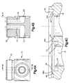
- the top surface of the flange 82 of the base 80 is provided with indicia of the type shown in FIGURE 3.
- the handle is provided with an opening through its upper surface so that the indicia on flange 82 is visible therethrough.
- the opening through the handle is a 90° slot which generally corresponds to the portion indicated with the letter C in the indicia markings.
- the red C area of the indicia shows through the opening indicating to an observer that the valve is in a closed position.
- the indicia is shown to change from a white/green combination to a full green open position.
- valve In addition to the manual operated arrangement, it is possible to operate the valve with other types of actuators such as the normally open actuator shown in FIGURE 8.
- This actuator is arranged so as to thread directly to the upper end of the body 10 and includes a bonnet nut 24' which clamps a shorter and modified bonnet element 90 into position to clamp the diaphragm in sealing engagement with the body 10.
- the interior of the bonnet 90 is threaded as shown at 92.
- the air actuator 94 has a housing 96 including a lower housing portion 98 that has a reduced diameter threaded end 100 which is threaded into the bonnet nut 90 as shown.
- the housing portion 98 defines a multiple diameter internal chamber which is threaded at its upper end as shown at 102 and receives a cap 104.
- the lower end surface 112a of the button 112 is slightly convex to closely match the top concave surface 40a of the seat 40.
- the piston 108 is sealed by a suitable 0-ring 114 located about its upper end. Normally, the piston is biased upwardly as shown to a valve opening position. The area below the piston 108 is vented to atmosphere through an opening 98a.
- a second piston member is carried above the first piston 108.
- the second piston 116 has a reduced diameter portion 118 that extends through an intermediate wall defining piston-like member 120 located generally centrally of the housing 94.
- the intermediate wall 120 is sealed by an 0-ring 122 and the reduced diameter portion 118 is also sealed by an 0-ring 124 where it passes through the wall 120.
- the area between the upper piston 116 and the intermediate piston 120 is vented to atmosphere through an opening 98b.
- Air supplied through inlet port 106 acts against the top surface of the piston 116 and is also conducted through the center opening 116a and the radial grooves 116b so as to fill the space between the lower surface of the wall 120 and the top surface of piston 108.
- this allows the downward force of both the area of the top piston 116 and the top of piston 108 to act against the force of spring 110 and move the valve to a closed position.
- the two piston arrangement provides a great force multiplication.
- FIGURE 7 shows the assembly directly connected to the valve body 10.
- the normally closed actuator assembly 130 is connected to the valve body 10 by the previously-mentioned bonnet nut 24' and the bonnet 90.
- a button element 112 with a lower surface 120 slightly convex to closely match the top concave surface 40a of the seat 40, is used to act directly against the diaphragm assembly 28 .
- the actuator assembly 130 includes a main housing member 132 having a lower end 134 of reduced diameter and threadedly received in the bonnet 90.
- the housing 132 has a stepped diameter interior as shown and carries a first piston member 136 at its lower end.
- the piston 136 is mounted for vertical reciprocation and is sealed by a central 0-ring 138. At its lower end, reduced diameter portion 140, it is also provided with an 0-ring 142 and is sealed within the reduced diameter opening within the end portion 134. Centrally of the housing member 132 there is a wall defining disk-like member 144 which is sealed about its outer periphery by an 0-ring 146. The area under the wall 144 is vented to atmosphere through an opening 148. The reduced diameter upper end portion 150 of the piston 136 is sealingly and sliding received through the central opening in the wall member 144 and sealed during movement therethrough by an 0-ring 152 .
- a second actuating piston 160 Positioned above the wall 144 for acting against the upper end of piston portion 150 is a second actuating piston 160 which is mounted for vertical reciprocation in the upper end of the housing member 132 and sealed about its periphery by an 0-ring 162.
- the reduced diameter upper end portion 164 of the upper piston 160 is provided with an O-ring 166 and is slidably received within a cylindrical bore 168 carried in an end cap member 170.
- the area above the upper piston 160 is vented to atmosphere through an opening 148a.
- the end cap member is threadedly and sealing received on the upper end of the housing member 132 and carries a relatively heavy coil spring 172 which acts downwardly against the piston 160 which in turn acts against the upper end 150 of piston 136.
- the valve is normally biased to a closed position.
- FIGURE 7 shows the valve in its open position however.
- air is supplied through the port 170a at the upper end of cap 170. It then flows through the central opening 160a to a position under the piston 160 where it exerts an upper force tending to act against the bias of spring 172.
- air is supplied through the central opening 136a to a position where it flows radially through a passage 136b to the space under piston 136. This biases piston 136 upwardly with the upper end portion 150 bearing against the underside of piston 160. This produces a multiplication of force acting in an upward direction allowing the diaphragm assembly 28 to move to the open position shown.
Landscapes
- Engineering & Computer Science (AREA)
- General Engineering & Computer Science (AREA)
- Mechanical Engineering (AREA)
- Fluid-Driven Valves (AREA)
- Lift Valve (AREA)
- Indication Of The Valve Opening Or Closing Status (AREA)
- Details Of Valves (AREA)
Description
Claims (16)
- A fluid flow control device comprising: a first body (26) and a second body (10); means for clamping (22,24) said first and second bodies together in an axially aligned relationship; a diaphragm (28) that is disposed axially between said first and second bodies to form a fluid seal there between; said diaphragm having a fluid flow side and a non-fluid flow side; each of said first and second bodies having a generally flat surface portion (30a, 26a) near its respective outer periphery; at least one of said generally flat surface portions (30a) being adjacent an outer corner (32) thereof; characterised in that said diaphragm being singularly clamped between said generally flat surface portions; said diaphragm having an outer peripheral portion (28a) adjacent said generally flat surface portions and that bends over and seals at said outer corner (32) radially outward from said singular clamp on said fluid flow side of the diaphragm.
- The device of claim 1 wherein a primary seal is formed between said diaphragm and said corner and a secondary seal is formed between said diaphragm and said generally flat surface portions.
- The device of claim 1 wherein said diaphragm is bent about a single corner.
- The device of claim 1 wherein said corner is formed between said generally flat surface and a second surface; said generally flat surface and said second surface being part of an annular collar that encircles an inlet passage and an outlet passage of the flow control device.
- The device of claim 4 wherein said second surface forms an included angle with said generally flat surface, said included angle being less than 180°.
- The device of claim 1 wherein said corner is initially formed as a sharp edge and wherein said corner yields when said diaphragm is compressed against said corner.
- The device of claim 6 wherein said corner yields to a radius.
- The device of claim 6 wherein said diaphragm comprises a material that is substantially harder than said body material.
- The device of claim 8 wherein said body comprises low carbon stainless steel and a bonnet of harder material than said body.
- The device of claim 1 wherein said outer corner is formed in said first body, said second body having a second corner formed adjacent its said generally flat surface; said second corner initially engaging said diaphragm outer peripheral portion before said diaphragm is clamped between said generally flat surfaces as said second body is made up with said first body.
- The device of claim 10 wherein said corner acts as a fulcrum with said diaphragm being sealingly bent around said corner when said first and second bodies are made up.
- The device of claim 1 wherein said clamped portion of said diaphragm reduces stress at said corner seal during cyclic operation of said diaphragm seal.
- The device of claim 10 wherein said second body extends outward radially from said second corner along a surface that axially extends toward said first body to form an edge that initially engages said diaphragm to begin bending said diaphragm about said corner during make-up of said first and second bodies, said second corner engaging said diaphragm after said initial engagement to further and sharply bend said diaphragm about said corner before said diaphragm is clamped between said generally flat surfaces.
- The device of claim 10 wherein said initial engagement applies tension to said diaphragm.
- The device of claim 14 wherein said diaphragm is annular and generally convex with a circumferential generally flat portion adjacent said diaphragm outer edge.
- A method for forming a body seal in a fluid flow control device of the type having a diaphragm (28) clamped between two bodies (10,26) of the valve; comprising the steps of:forming one of said bodies (10) with a first flat portion (30a) and an adjacent first corner (32);forming the other body (26) with a second flat portion (26a) and an adjacent second corner (26c); wherein said second flat portion axially opposes said first flat portion when said bodies are assembled;and during assembly of said bodies together, said second corner (26c) initially engaging the diaphragm (28) to bend the diaphragm sharply about said first comer (32) to form a seal; andsingularly clamping said diaphragm between said first and second flat portions after said diaphragm is bent around said first corner.
Priority Applications (1)
| Application Number | Priority Date | Filing Date | Title |
|---|---|---|---|
| EP03006419A EP1323964A3 (en) | 1997-02-03 | 1998-01-30 | Diaphragm valve |
Applications Claiming Priority (5)
| Application Number | Priority Date | Filing Date | Title |
|---|---|---|---|
| US3769897P | 1997-02-03 | 1997-02-03 | |
| US37698P | 1997-02-03 | ||
| US7299598P | 1998-01-29 | 1998-01-29 | |
| US72995P | 1998-01-29 | ||
| PCT/US1998/001743 WO1998034056A2 (en) | 1997-02-03 | 1998-01-30 | Diaphragm valve |
Related Child Applications (1)
| Application Number | Title | Priority Date | Filing Date |
|---|---|---|---|
| EP03006419A Division EP1323964A3 (en) | 1997-02-03 | 1998-01-30 | Diaphragm valve |
Publications (2)
| Publication Number | Publication Date |
|---|---|
| EP0941435A2 EP0941435A2 (en) | 1999-09-15 |
| EP0941435B1 true EP0941435B1 (en) | 2003-05-21 |
Family
ID=26714394
Family Applications (1)
| Application Number | Title | Priority Date | Filing Date |
|---|---|---|---|
| EP98906044A Expired - Lifetime EP0941435B1 (en) | 1997-02-03 | 1998-01-30 | Diaphragm valve |
Country Status (8)
| Country | Link |
|---|---|
| US (2) | US6092550A (en) |
| EP (1) | EP0941435B1 (en) |
| JP (2) | JP2002513457A (en) |
| KR (1) | KR100514761B1 (en) |
| CN (2) | CN1107831C (en) |
| DE (1) | DE69814815T2 (en) |
| IL (1) | IL130567A (en) |
| WO (1) | WO1998034056A2 (en) |
Families Citing this family (55)
| Publication number | Priority date | Publication date | Assignee | Title |
|---|---|---|---|---|
| PT1368587E (en) | 2001-02-20 | 2008-02-14 | Nl Technologies Ltd | Circumferential sealing diaphragm valve |
| JP4700234B2 (en) * | 2001-07-31 | 2011-06-15 | 株式会社フジキン | Diaphragm valve |
| DE10139815A1 (en) * | 2001-08-14 | 2003-03-13 | Friatec Sed Ventilsysteme Gmbh | diaphragm valve |
| US20050224744A1 (en) * | 2002-02-20 | 2005-10-13 | Nl Technologies, Ltd. | Circumferential sealing diaphragm valve |
| ITSV20020032A1 (en) * | 2002-07-09 | 2004-01-09 | Alberto Lodolo | DIAPHRAGM VALVE AND SHUTTER FOR SUCH VALVE |
| JP4310532B2 (en) * | 2002-11-27 | 2009-08-12 | Smc株式会社 | Flow control valve |
| TW572164U (en) * | 2002-12-06 | 2004-01-11 | Ind Tech Res Inst | Diaphragm valve |
| CA2462342C (en) * | 2003-03-28 | 2010-10-12 | Pn Ii, Inc. | Universal rake-ridge cap |
| EP1613882A2 (en) * | 2003-04-14 | 2006-01-11 | Swagelok Company | Diaphragm valve seat |
| US6941963B2 (en) * | 2003-06-26 | 2005-09-13 | Planar Systems, Inc. | High-speed diaphragm valve for atomic layer deposition |
| US7021330B2 (en) * | 2003-06-26 | 2006-04-04 | Planar Systems, Inc. | Diaphragm valve with reliability enhancements for atomic layer deposition |
| US6907897B2 (en) * | 2003-06-26 | 2005-06-21 | Planar Systems, Inc. | Diaphragm valve for high-temperature precursor supply in atomic layer deposition |
| JP2007525622A (en) * | 2003-10-03 | 2007-09-06 | スワゲロック カンパニー | Diaphragm monitoring for flow control devices |
| US20050109973A1 (en) * | 2003-11-21 | 2005-05-26 | Glime William H. | Valve diaphragm |
| JP2005188672A (en) * | 2003-12-26 | 2005-07-14 | Neriki:Kk | Valve device |
| WO2005073605A1 (en) * | 2004-01-29 | 2005-08-11 | Asahi Organic Chemicals Industry Co., Ltd. | Valve |
| US6997440B2 (en) * | 2004-03-29 | 2006-02-14 | Tescom Corporation | Packless valve apparatus |
| TWM276133U (en) * | 2004-12-07 | 2005-09-21 | Metal Ind Res & Dev Ct | Pushing block applied in the valve |
| JP2009501878A (en) * | 2005-07-13 | 2009-01-22 | スウエイジロク・カンパニー | Operating method and equipment |
| KR20080045699A (en) * | 2005-08-09 | 2008-05-23 | 스와겔로크 컴패니 | Fluid flow device |
| USD548309S1 (en) * | 2005-09-01 | 2007-08-07 | Adaptor, Inc. | Gate valve sealing structure |
| USD546924S1 (en) * | 2005-09-01 | 2007-07-17 | Adaptor, Inc. | Gate valve sealing structure |
| USD577106S1 (en) | 2005-09-01 | 2008-09-16 | Adaptor, Inc. | Gate valve sealing structure |
| DE602005012849D1 (en) * | 2005-12-13 | 2009-04-02 | Pergola S R L | Diaphragm valve for compressed or liquefied gas |
| US7686280B2 (en) * | 2005-12-28 | 2010-03-30 | Circor Instrumentation Technologies, Inc. | Removable valve seat member for diaphragm valve |
| WO2007104334A1 (en) * | 2006-03-15 | 2007-09-20 | Norgren Gmbh | Valve with a springy diaphragm |
| US7971599B2 (en) * | 2006-06-20 | 2011-07-05 | Ckd Corporation | Air-operated valve |
| US8172197B2 (en) * | 2006-07-06 | 2012-05-08 | Mks Instruments, Inc. | Fast-acting pneumatic diaphragm valve |
| EP2225502B1 (en) * | 2007-11-13 | 2011-05-25 | Danfoss A/S | Expansion valve |
| WO2010045946A1 (en) * | 2008-10-21 | 2010-04-29 | Danfoss A/S | A servo valve |
| JP5613420B2 (en) * | 2010-02-05 | 2014-10-22 | 株式会社フジキン | Fluid controller |
| WO2011109502A1 (en) * | 2010-03-04 | 2011-09-09 | Bio-Rad Laboratories, Inc. | Diaphragm valve |
| US8960216B2 (en) * | 2011-03-21 | 2015-02-24 | Tescom Corporation | Diaphragm control valve having a universal diaphragm mounting location |
| JP5779559B2 (en) * | 2012-08-31 | 2015-09-16 | 株式会社フジキン | Diaphragm valve |
| KR102207127B1 (en) | 2013-02-01 | 2021-01-22 | 스와겔로크 컴패니 | Diaphragm valve with welded diaphragm seat carrier |
| CN105473915A (en) * | 2013-03-11 | 2016-04-06 | 滨特尔民用水处理有限责任公司 | Mechanical pressure switch |
| CN104062057B (en) * | 2013-03-20 | 2019-06-11 | 费希尔久安输配设备(成都)有限公司 | A kind of diaphragm clamp device and the sensing device comprising the diaphragm clamp device |
| JP6111862B2 (en) * | 2013-05-24 | 2017-04-12 | 日立金属株式会社 | Flow control valve and mass flow controller using the same |
| JP6218470B2 (en) * | 2013-07-18 | 2017-10-25 | 株式会社フジキン | Diaphragm valve |
| JP6232224B2 (en) | 2013-07-26 | 2017-11-15 | 株式会社フジキン | Diaphragm valve |
| JP6286558B2 (en) * | 2013-08-26 | 2018-02-28 | パーカー・ハニフィン・コーポレーション | High cycle high speed valve |
| JP2017503123A (en) | 2013-11-28 | 2017-01-26 | ハム−レット (イスラエル−カナダ) リミテッド | Valve device for controlling and regulating fluid flow |
| JP6564593B2 (en) * | 2015-03-25 | 2019-08-21 | 株式会社フジキン | Diaphragm valve |
| JP6654020B2 (en) * | 2015-11-13 | 2020-02-26 | 株式会社フジキン | Diaphragm valve and method of manufacturing the same |
| US10352470B2 (en) * | 2015-11-17 | 2019-07-16 | Ge Aviation Systems Llc | Control valve and air starting system |
| CN105382458B (en) * | 2015-11-24 | 2017-07-11 | 山西江淮重工有限责任公司 | Diaphragm and steam ball valve valve seat group mounted welder and its assembly welding technique |
| US10584796B2 (en) * | 2016-08-02 | 2020-03-10 | GE AViation systems, ILC | Seal, assembly, and retention method |
| CN109477587B (en) * | 2016-08-25 | 2021-09-24 | 株式会社开滋Sct | Diaphragm valves and flow control equipment for semiconductor manufacturing equipment |
| KR102239202B1 (en) * | 2017-07-04 | 2021-04-09 | 가부시키가이샤 후지킨 | Actuators, valves, fluid supply systems and semiconductor manufacturing equipment |
| US10774938B2 (en) | 2017-11-09 | 2020-09-15 | Swagelok Company | Diaphragm valve with metal seat |
| JP7045839B2 (en) * | 2017-12-08 | 2022-04-01 | 株式会社キッツエスシーティー | Fluid control valve |
| US20190323625A1 (en) | 2018-04-23 | 2019-10-24 | Rain Bird Corporation | Valve With Reinforcement Ports And Manually Removable Scrubber |
| JP2018132194A (en) * | 2018-05-01 | 2018-08-23 | 株式会社フジキン | Diaphragm valve, fluid control device, semiconductor control device, and semiconductor control method |
| CN117480335A (en) | 2021-04-16 | 2024-01-30 | 道格拉斯·亚瑟·纽伯格 | valve actuator assembly |
| US12117090B2 (en) * | 2021-08-04 | 2024-10-15 | Gemü Gebr. Müller Apparatebau Gmbh & Co. Kommanditgesellschaft | Tensioning assembly for a process valve |
Family Cites Families (39)
| Publication number | Priority date | Publication date | Assignee | Title |
|---|---|---|---|---|
| US954172A (en) * | 1908-05-23 | 1910-04-05 | American Gasaccumulator Company | Valve. |
| GB199672A (en) * | 1922-12-11 | 1923-06-28 | Robert Arnold Blakeborough | New or improved method of or means for securing seating rings to valves or valve bodies |
| US2209956A (en) | 1938-03-04 | 1940-08-06 | Squibb & Sons Inc | Dispensing apparatus |
| GB875446A (en) * | 1956-11-12 | 1961-08-23 | Baltzar Carl Von Platen | Improvements in or relating to cocks |
| US2959392A (en) * | 1957-11-08 | 1960-11-08 | Platen Baltzar Carl Von | Fluid-tight valve seat |
| GB1015412A (en) * | 1962-03-24 | 1965-12-31 | Seetru Ltd | Improvements in and relating to resilient sealing rings for fluid valves |
| FR1358512A (en) * | 1963-03-04 | 1964-04-17 | Electrochimie Soc | High pressure valve |
| US3430539A (en) * | 1967-11-02 | 1969-03-04 | Scovill Manufacturing Co | Pneumatic tool |
| JPS6025956B2 (en) * | 1980-12-10 | 1985-06-21 | 松下電器産業株式会社 | Ultrasonic transducer |
| US4421295A (en) * | 1981-08-13 | 1983-12-20 | American Standard, Inc. | Valve diaphragm |
| US4684106A (en) * | 1983-04-05 | 1987-08-04 | Nupro Company | Valve |
| US4606374A (en) | 1983-04-05 | 1986-08-19 | Nupro Company | Valve |
| US4644847A (en) * | 1983-05-16 | 1987-02-24 | Fluitron, Inc. | Reduction of failure incidence of metallic diaphragms for compressors |
| CA1276133C (en) * | 1985-03-29 | 1990-11-13 | Ryozo Ariizumi | Pneumatically operated valve |
| US4732363A (en) | 1986-05-16 | 1988-03-22 | Nupro Company | Diaphragm valve |
| US4671490A (en) | 1986-05-16 | 1987-06-09 | Nupro Co. | Diaphragm valve |
| US4750709A (en) * | 1986-05-16 | 1988-06-14 | Nupro Company | Diaphragm valve |
| JPS63115970A (en) * | 1986-10-31 | 1988-05-20 | Motoyama Seisakusho:Kk | Diaphragm valve |
| JPS643387A (en) * | 1987-06-24 | 1989-01-09 | Nippon Diavalve | Tandem piston device for valve |
| US4776562A (en) * | 1987-07-28 | 1988-10-11 | Stanley G. Flagg & Co. | Dual piston pneumatically operated valve |
| US4903939A (en) * | 1988-03-14 | 1990-02-27 | Fujikura Rubber, Ltd. | Pneumatically-operated valve |
| DE3808478C2 (en) * | 1988-03-14 | 1995-12-07 | Fujikura Rubber Ltd | Pneumatically operated valve |
| JPH0730847B2 (en) * | 1988-06-13 | 1995-04-10 | 株式会社フジキン | Fluid break opener |
| JPH0251671A (en) * | 1988-08-12 | 1990-02-21 | Motoyama Seisakusho:Kk | Metal diaphragm valve |
| US4905575A (en) * | 1988-10-20 | 1990-03-06 | Rosemount Inc. | Solid state differential pressure sensor with overpressure stop and free edge construction |
| JPH0627552B2 (en) * | 1989-04-11 | 1994-04-13 | 日本弁管工業株式会社 | Diaphragm valve |
| US5112027A (en) * | 1989-06-21 | 1992-05-12 | Benkan Corporation | Metal diaphragm valve |
| US5007328A (en) * | 1989-07-24 | 1991-04-16 | Otteman John H | Linear actuator |
| US4934652A (en) * | 1989-12-11 | 1990-06-19 | Otis Engineering Corporation | Dual stage valve actuator |
| US5131627A (en) * | 1990-10-17 | 1992-07-21 | Nupro Company | Diaphragm valve |
| JP3006913B2 (en) * | 1991-05-09 | 2000-02-07 | 清原 まさ子 | Fluid controller |
| JPH086828B2 (en) * | 1991-08-09 | 1996-01-29 | 株式会社ベンカン | Metal diaphragm valve |
| US5295662A (en) * | 1991-08-26 | 1994-03-22 | Masako Kiyohara | Fluid flow-controller with improved diaphragm |
| JPH0643429U (en) * | 1992-11-12 | 1994-06-10 | 株式会社ベンカン | Diaphragm valve with closing lock mechanism |
| JP3280119B2 (en) * | 1993-06-02 | 2002-04-30 | 清原 まさ子 | Diaphragm valve |
| US5326078A (en) * | 1993-07-08 | 1994-07-05 | Benkan Corporation | Metal diaphragm valve |
| US5413311A (en) * | 1994-03-01 | 1995-05-09 | Tescom Corporation | Gas valve |
| JP3291152B2 (en) * | 1995-02-15 | 2002-06-10 | 株式会社フジキン | Diaphragm valve |
| US5725007A (en) * | 1995-07-07 | 1998-03-10 | Stubbs; William L. | Valve mechanism and method for making same |
-
1998
- 1998-01-30 US US09/015,751 patent/US6092550A/en not_active Expired - Fee Related
- 1998-01-30 CN CN98802286A patent/CN1107831C/en not_active Expired - Fee Related
- 1998-01-30 WO PCT/US1998/001743 patent/WO1998034056A2/en not_active Ceased
- 1998-01-30 IL IL13056798A patent/IL130567A/en not_active IP Right Cessation
- 1998-01-30 JP JP53307098A patent/JP2002513457A/en not_active Ceased
- 1998-01-30 EP EP98906044A patent/EP0941435B1/en not_active Expired - Lifetime
- 1998-01-30 DE DE1998614815 patent/DE69814815T2/en not_active Expired - Fee Related
- 1998-01-30 KR KR10-1999-7006851A patent/KR100514761B1/en not_active Expired - Fee Related
-
2000
- 2000-02-22 US US09/511,422 patent/US6189861B1/en not_active Expired - Lifetime
-
2002
- 2002-07-10 CN CN02126158A patent/CN1447050A/en active Pending
-
2008
- 2008-08-12 JP JP2008207885A patent/JP2008304067A/en not_active Withdrawn
Also Published As
| Publication number | Publication date |
|---|---|
| JP2008304067A (en) | 2008-12-18 |
| IL130567A (en) | 2002-04-21 |
| US6189861B1 (en) | 2001-02-20 |
| WO1998034056A3 (en) | 1998-11-12 |
| DE69814815D1 (en) | 2003-06-26 |
| US6092550A (en) | 2000-07-25 |
| JP2002513457A (en) | 2002-05-08 |
| CN1447050A (en) | 2003-10-08 |
| KR20000070604A (en) | 2000-11-25 |
| KR100514761B1 (en) | 2005-09-15 |
| DE69814815T2 (en) | 2004-04-08 |
| WO1998034056A2 (en) | 1998-08-06 |
| CN1246915A (en) | 2000-03-08 |
| CN1107831C (en) | 2003-05-07 |
| IL130567A0 (en) | 2000-06-01 |
| EP0941435A2 (en) | 1999-09-15 |
Similar Documents
| Publication | Publication Date | Title |
|---|---|---|
| US6092550A (en) | Diaphragm valve seat arrangement | |
| US5253671A (en) | High pressure diaphragm valve | |
| EP0620391B1 (en) | High pressure diaphragm valve | |
| US5586569A (en) | Pneumatic pressure regulator | |
| US4526341A (en) | Pneumatic shut-off valve | |
| EP0246109B1 (en) | Valve | |
| AU2020200555B2 (en) | Proportional Flow Control Valve Poppet With Flow Control Needle | |
| EP0795707A1 (en) | Poppet Valve | |
| US3982729A (en) | Back-up seal for diaphragm valve | |
| US20030025099A1 (en) | Diaphragm valve | |
| US4561464A (en) | Relay valve | |
| US6953182B2 (en) | Retainer lock nut for fluid pressure control device | |
| US6997440B2 (en) | Packless valve apparatus | |
| EP1323964A2 (en) | Diaphragm valve | |
| US4807849A (en) | Fluid flow control device and compression member therefor | |
| EP0233087A2 (en) | Valve member | |
| EP1845430B1 (en) | Pressure reducing valve | |
| JP3347960B2 (en) | Control valve | |
| KR102256186B1 (en) | Regulator | |
| US4312389A (en) | Valve mechanism of rolling seal type and gas lighter valves using the same | |
| CA2197790C (en) | Gas cylinder valve with non-perforated diaphragms | |
| GB1604576A (en) | Valves | |
| GB1601210A (en) | Diaphragm valve | |
| GB2041501A (en) | Pilot-assisted fluid flow control valve |
Legal Events
| Date | Code | Title | Description |
|---|---|---|---|
| PUAI | Public reference made under article 153(3) epc to a published international application that has entered the european phase |
Free format text: ORIGINAL CODE: 0009012 |
|
| 17P | Request for examination filed |
Effective date: 19990716 |
|
| AK | Designated contracting states |
Kind code of ref document: A2 Designated state(s): DE FR GB IT |
|
| RAP1 | Party data changed (applicant data changed or rights of an application transferred) |
Owner name: SWAGELOK COMPANY |
|
| RIN1 | Information on inventor provided before grant (corrected) |
Inventor name: SMITH, PHILIP, J. Inventor name: RASANOW, VICTOR, N. Inventor name: LONGO, MARIA Inventor name: KITCHEN, DALE, J. Inventor name: GOTCH, JAMES, E. |
|
| 17Q | First examination report despatched |
Effective date: 20010517 |
|
| GRAH | Despatch of communication of intention to grant a patent |
Free format text: ORIGINAL CODE: EPIDOS IGRA |
|
| GRAH | Despatch of communication of intention to grant a patent |
Free format text: ORIGINAL CODE: EPIDOS IGRA |
|
| GRAA | (expected) grant |
Free format text: ORIGINAL CODE: 0009210 |
|
| AK | Designated contracting states |
Designated state(s): DE FR GB IT |
|
| REG | Reference to a national code |
Ref country code: GB Ref legal event code: FG4D |
|
| REF | Corresponds to: |
Ref document number: 69814815 Country of ref document: DE Date of ref document: 20030626 Kind code of ref document: P |
|
| ET | Fr: translation filed | ||
| PLBE | No opposition filed within time limit |
Free format text: ORIGINAL CODE: 0009261 |
|
| STAA | Information on the status of an ep patent application or granted ep patent |
Free format text: STATUS: NO OPPOSITION FILED WITHIN TIME LIMIT |
|
| 26N | No opposition filed |
Effective date: 20040224 |
|
| PGFP | Annual fee paid to national office [announced via postgrant information from national office to epo] |
Ref country code: FR Payment date: 20050117 Year of fee payment: 8 |
|
| PGFP | Annual fee paid to national office [announced via postgrant information from national office to epo] |
Ref country code: GB Payment date: 20050126 Year of fee payment: 8 |
|
| PGFP | Annual fee paid to national office [announced via postgrant information from national office to epo] |
Ref country code: DE Payment date: 20050228 Year of fee payment: 8 |
|
| PG25 | Lapsed in a contracting state [announced via postgrant information from national office to epo] |
Ref country code: GB Free format text: LAPSE BECAUSE OF NON-PAYMENT OF DUE FEES Effective date: 20060130 |
|
| PG25 | Lapsed in a contracting state [announced via postgrant information from national office to epo] |
Ref country code: FR Free format text: LAPSE BECAUSE OF NON-PAYMENT OF DUE FEES Effective date: 20060131 |
|
| PGFP | Annual fee paid to national office [announced via postgrant information from national office to epo] |
Ref country code: IT Payment date: 20060131 Year of fee payment: 9 |
|
| PG25 | Lapsed in a contracting state [announced via postgrant information from national office to epo] |
Ref country code: DE Free format text: LAPSE BECAUSE OF NON-PAYMENT OF DUE FEES Effective date: 20060801 |
|
| GBPC | Gb: european patent ceased through non-payment of renewal fee |
Effective date: 20060130 |
|
| REG | Reference to a national code |
Ref country code: FR Ref legal event code: ST Effective date: 20060929 |
|
| PG25 | Lapsed in a contracting state [announced via postgrant information from national office to epo] |
Ref country code: IT Free format text: LAPSE BECAUSE OF NON-PAYMENT OF DUE FEES Effective date: 20070130 |