EP0940340B1 - Method and unit for transferring a group of cigarettes continuously between conveyors - Google Patents
Method and unit for transferring a group of cigarettes continuously between conveyors Download PDFInfo
- Publication number
- EP0940340B1 EP0940340B1 EP99104386A EP99104386A EP0940340B1 EP 0940340 B1 EP0940340 B1 EP 0940340B1 EP 99104386 A EP99104386 A EP 99104386A EP 99104386 A EP99104386 A EP 99104386A EP 0940340 B1 EP0940340 B1 EP 0940340B1
- Authority
- EP
- European Patent Office
- Prior art keywords
- seat
- group
- conveyor
- along
- respect
- Prior art date
- Legal status (The legal status is an assumption and is not a legal conclusion. Google has not performed a legal analysis and makes no representation as to the accuracy of the status listed.)
- Expired - Lifetime
Links
Images


Classifications
-
- B—PERFORMING OPERATIONS; TRANSPORTING
- B65—CONVEYING; PACKING; STORING; HANDLING THIN OR FILAMENTARY MATERIAL
- B65B—MACHINES, APPARATUS OR DEVICES FOR, OR METHODS OF, PACKAGING ARTICLES OR MATERIALS; UNPACKING
- B65B19/00—Packaging rod-shaped or tubular articles susceptible to damage by abrasion or pressure, e.g. cigarettes, cigars, macaroni, spaghetti, drinking straws or welding electrodes
- B65B19/02—Packaging cigarettes
- B65B19/22—Wrapping the cigarettes; Packaging the cigarettes in containers formed by folding wrapping material around formers
- B65B19/223—Wrapping the cigarettes; Packaging the cigarettes in containers formed by folding wrapping material around formers in a curved path; in a combination of straight and curved paths, e.g. on rotary tables or other endless conveyors
- B65B19/225—Wrapping the cigarettes; Packaging the cigarettes in containers formed by folding wrapping material around formers in a curved path; in a combination of straight and curved paths, e.g. on rotary tables or other endless conveyors the conveyors having continuous movement
-
- B—PERFORMING OPERATIONS; TRANSPORTING
- B65—CONVEYING; PACKING; STORING; HANDLING THIN OR FILAMENTARY MATERIAL
- B65B—MACHINES, APPARATUS OR DEVICES FOR, OR METHODS OF, PACKAGING ARTICLES OR MATERIALS; UNPACKING
- B65B19/00—Packaging rod-shaped or tubular articles susceptible to damage by abrasion or pressure, e.g. cigarettes, cigars, macaroni, spaghetti, drinking straws or welding electrodes
- B65B19/02—Packaging cigarettes
- B65B19/04—Arranging, feeding, or orientating the cigarettes
-
- B—PERFORMING OPERATIONS; TRANSPORTING
- B65—CONVEYING; PACKING; STORING; HANDLING THIN OR FILAMENTARY MATERIAL
- B65G—TRANSPORT OR STORAGE DEVICES, e.g. CONVEYORS FOR LOADING OR TIPPING, SHOP CONVEYOR SYSTEMS OR PNEUMATIC TUBE CONVEYORS
- B65G47/00—Article or material-handling devices associated with conveyors; Methods employing such devices
- B65G47/74—Feeding, transfer, or discharging devices of particular kinds or types
- B65G47/84—Star-shaped wheels or devices having endless travelling belts or chains, the wheels or devices being equipped with article-engaging elements
- B65G47/846—Star-shaped wheels or wheels equipped with article-engaging elements
- B65G47/847—Star-shaped wheels or wheels equipped with article-engaging elements the article-engaging elements being grippers
-
- B—PERFORMING OPERATIONS; TRANSPORTING
- B65—CONVEYING; PACKING; STORING; HANDLING THIN OR FILAMENTARY MATERIAL
- B65G—TRANSPORT OR STORAGE DEVICES, e.g. CONVEYORS FOR LOADING OR TIPPING, SHOP CONVEYOR SYSTEMS OR PNEUMATIC TUBE CONVEYORS
- B65G2201/00—Indexing codes relating to handling devices, e.g. conveyors, characterised by the type of product or load being conveyed or handled
- B65G2201/02—Articles
- B65G2201/0226—Cigarettes
Definitions
- the present invention relates to a method of transferring a group of cigarettes continuously between conveyors.
- the present invention relates to a method of continuously transferring a group of cigarettes from a seat on a continuous supply conveyor to a corresponding seat on a continuous wrapping conveyor or wheel.
- group of cigarettes is intended to mean a number of cigarettes arranged in a number of layers with no outer sheet of wrapping material, i.e. a number of cigarettes which, to remain together, need some sort of outer retaining wrapping.
- the supply conveyor is normally defined by a chain or belt conveyor, the seats of which are fed along a path having one portion - hereinafter referred to as the "transfer portion" - which reproduces a portion of the circular path along which the seats on the wrapping wheel are fed.
- the seats on the supply conveyor are moved in time, and maintained coaxial, with the corresponding seats on the wrapping wheel to transfer the group of cigarettes axially between two corresponding coaxial seats.
- Axial transfer involves several drawbacks by subjecting the group of cigarettes to fairly severe mechanical stress (especially on modern packing machines capable of producing over ten packets a second) which may result in deformation of the cigarettes or tobacco fallout.
- Axial transfer also requires that the supply conveyor and wrapping wheel be positioned side by side, i.e. in two different planes, which therefore increases the overall depth of the transfer unit and complicates control and maintenance.
- EP Patent No. 548,978 discloses a unit for continuously transferring a group of cigarettes between relevant seats of two wrapping wheels. At a given transfer zone the seats on the two wheels are maintained facing and parallel to each other and to a fixed direction - in particular, a direction perpendicular to the respective axes of rotation of the wheels - by moving, in particular oscillating, the seats continuously with respect to the respective wheels.
- the present invention also relates to a unit for transferring a group of cigarettes continuously between conveyors.
- a unit for transferring a group of cigarettes continuously between conveyors as defined in appended claim 12.
- Number 1 in Figure 1 indicates as a whole a transfer unit forming part of a continuous automatic packing machine for producing packets of cigarettes not shown.
- a group 2 of cigarettes is formed (in known manner not shown) inside a respective seat 3 fed continuously and a direction D1 along a path P1 by an endless forming conveyor 4, and is then transferred to a corresponding seat 5 fed continuously and in a direction D2 along a path P2 by an endless wrapping conveyor defined by a wrapping wheel 6.
- Path P1 is coplanar with path P2, and comprises an initial loading portion P3 at a loading station S1, and a final transfer portion P4 at a transfer station S2 where the group 2 of cigarettes is transferred by a seat 7 carried by a transmission pulley 8 of conveyor 4.
- Seat 7 is a movable seat for receiving group 2 from seat 3 on forming conveyor 4 and feeding group 2 to the corresponding seat 5 on wrapping wheel 6.
- pulley 8 feeds each seat 7 along a path substantially coincident with transfer portion P4 of path P1.
- Group 2 is confined within a substantially parallelepiped space defined by a pair of parallel large lateral surfaces 9a, and by a pair of parallel small lateral surfaces 9b perpendicular to surfaces 9a. As shown more clearly in Figure 4, said space also comprises two opposite longitudinal ends 9c, and a central portion 9d interposed between the two longitudinal ends 9c.
- group 2 is conveyed by forming conveyor 4 with a first orientation with respect to direction D1, and wherein small lateral surfaces 9b are substantially perpendicular to direction D1; and along path P2, group 2 is conveyed by wrapping wheel 6 with a second orientation with respect to direction D2, and wherein large lateral surfaces 9a are substantially perpendicular to direction D2.
- group 2 is obviously rotated 90° about its own longitudinal axis (not shown) parallel to the cigarettes forming group 2.
- each seat 5 Before being fed through transfer station S2, each seat 5 is fed through a supply station (not shown) where seat 5 receives a sheet 10 of foil wrapping material, which is folded into a U inside seat 5, and in which a respective group 2 is wrapped after being transferred to corresponding seat 5.
- Wrapping wheel 6 comprises a cylinder 11 powered to rotate continuously (clockwise in Figure 1) about a central axis 12 perpendicular to the Figure 1 plane; and a number of peripheral heads 13 (only one shown) equally spaced about axis 12.
- Each head 13 defines a respective seat 5 for first receiving and conveying a respective sheet 10 of wrapping material folded substantially into a U, and for subsequently receiving and conveying a respective group 2 of cigarettes, which is wrapped in sheet 10 of wrapping material as the group is fed along path P2.
- Each head 13 is hinged to cylinder 11 and is oscillated about an axis 14 parallel to axis 12 by a known cam control device 15 (shown schematically in Figure 1); and seat 5 of each head 13 is defined by an end wall 16 fitted to head 13, and by two lateral walls 17, which are hinged to opposite ends of wall 16 and are oscillated, by a control device 19 and about respective axes 18 parallel to axis 12, between an open and a closed position.
- control device 19 comprises a slide 19a supporting end wall 16 and which is moved along head 13, in a direction perpendicular to end wall 16, by a known cam device (not shown); and two ties 19b, each of which is interposed between head 13 and an intermediate point along a respective lateral wall 17, so that each axial movement of slide 19a with respect to head 13 rotates lateral walls 17 about respective axes 18.
- each seat 5 In the open position, the two lateral walls 17 of each seat 5 form an obtuse angle with end wall 16, and seat 5 has a section in the form of an isosceles trapezium. In the closed position, the two lateral walls 17 of each seat 5 substantially form a right angle with end wall 16, and seat 5 has a rectangular section of substantially the same size as group 2 so as to engage group 2 completely, i.e. at both central portion 9d and longitudinal ends 9c.
- the inner surfaces of walls 16 and 17 comprise a number of holes (not shown) connected to a known suction device (not shown) carried by wrapping wheel 6.
- Each head 13 also comprises a known folding device or arm 20, which is hinged to head 13 and oscillated about axis 14 by a known cam device (not shown) to longitudinally fold a projecting portion of a sheet 10 of wrapping material folded into a U about a respective group 2 of cigarettes and housed inside seat 5.
- a known folding device or arm 20 which is hinged to head 13 and oscillated about axis 14 by a known cam device (not shown) to longitudinally fold a projecting portion of a sheet 10 of wrapping material folded into a U about a respective group 2 of cigarettes and housed inside seat 5.
- Forming conveyor 4 comprises a known flexible endless toothed belt 21 (shown partly in Figure 1) fed along path P1 (shown partly in Figure 1) by pulley 8, which comprises a toothed central roller 22 rotating continuously (anticlockwise in Figure 1) about a central axis 23 parallel to axis 12.
- Loading station S1 is shown schematically in Figure 1 and, in a first embodiment, is substantially located at the point at which a complete group 2 of cigarettes is fed to a respective seat 3 by a known forming unit not shown.
- conveyor 4 is a forming conveyor for forming groups 2
- loading station S1 is substantially located along a portion of conveyor 4 in which a group 2 of cigarettes is formed layer by layer inside a respective seat 3 by a known hopper-type forming device (not shown) as described for example in US Patent No. 5,070,991.
- Transfer portion P4 of path P1 is located at transfer station S2 and at pulley 8, and extends substantially along an initial portion of a curved portion of path P1 extending about axis 23.
- Conveyor 4 also comprises a number of heads 24 (only one shown) carried by and equally spaced along belt 21. As shown more clearly in Figure 2, each head 24 defines a respective seat 3 having a longitudinal dimension (perpendicular to the Figure 2 plane) smaller than that of group 2, and having a rectangular section of substantially the same transverse size as group 2, so as to engage group 2 by central portion 9d while leaving respective longitudinal ends 9c substantially free.
- Each head 24 is connected to belt 21 in substantially fixed manner by means of two pins 25, which cooperate with respective seats 26 on head 24 to enable head 24 to move slightly with respect to belt 21 to adjust to the curved portions of path P1.
- Each head 24 has a retaining device 27 comprising two jaws 28 integral with belt 21 and which oscillate between a gripping position (as shown for example in Figure 2a) along the straight portions of belt 21, and a release position (as shown for example in Figure 2c) along the curved portions (only one shown) of belt 21.
- pulley 8 comprises two flanges 29 (only one shown) coaxial with axis 23 and supporting, in between, a number of peripheral heads 30 (only one shown in Figure 1) equally spaced about axis 23 and mounted for rotation about respective axes 31 parallel to axis 23.
- each head 30 has a pin 32 coaxial with axis 31 and fitted at opposite ends to two appendixes 33 of respective flanges 29; each head 30 comprises two gripping devices 34, which together define a respective seat 7; and each gripping device 34 comprises two relatively thin L-clamps 35 located in the same plane perpendicular to axis 31, and movable, with respect to each other and in said plane, between a release position ( Figure 5a) and a gripping position ( Figure 5b) in which clamps 35 define a tubular seat 35a having an axis parallel to axis 31 and a rectangular section of approximately the same size as but no larger than the cross section of a group 2.
- Each gripping device 34 is fitted to a respective rocker arm 36 hinged about axis 31 by a central sleeve 37 fitted in rotary and axially-sliding manner to respective pin 32.
- each sleeve 37 is controlled by an actuating and control device 38, which comprises an arm 39 projecting radially from sleeve 37 and fitted on the free end with a tappet roller 40, which rotates about a respective axis perpendicular to axis 31 and engages a track 41 formed in a fixed cam 42 located between flanges 29 and forming part of device 38.
- Track 41 extends about axis 23 to control the axial position of sleeve 37 along respective pin 32 alongside variations in the angular position of respective seat 7 about axis 23.
- Actuating and control device 38 also comprises, for each sleeve 37, an arm 43 projecting radially from sleeve 37; and a tappet roller 44 fitted to the free end of arm 43 to rotate, about a respective axis parallel to axis 31, along a respective track 45 formed on cam 42 and extending about axis 23 to control the angular position of sleeve 37 about axis 31 of respective pin 32 alongside variations in the angular position of respective seat 7 about axis 23.
- Each gripping device 34 also has an actuating device 46 comprising an articulated parallelogram 47, which in turn comprises two parallel rods 48 hinged to rocker arm 36, and two parallel rods 49, each fitted at one end with a respective L-clamp 35 of gripping device 34.
- One of the two rods 49, indicated 49a, is fitted, on the opposite end to that supporting respective clamp 35, with a tappet roller 50 mounted for rotation, about a respective axis parallel to axis 31, along a respective track 51 formed on cam 42 and extending about axis 23 to control the axial position of rod 49a with respect to respective pin 32 alongside variations in the angular position of respective seat about axis 23.
- Track 41 of cam 42 is so formed that, as pulley 8 rotates about axis 23, the two rocker arms 36 of each seat 7 are moved, along axis 31 of respective pin 32, between an open position of respective gripping device 34 - wherein the two tubular seats 35a are separated by a distance greater than the length of a respective group 2 of cigarettes - and a closed position of respective gripping device 34 - wherein the two tubular seats 35a define respective seat 7 and grip and retain a respective group 2 of cigarettes by engaging ends 9c of group 2.
- Track 45 of cam 42 is so formed that, as pulley 8 rotates about axis 23, the two rocker arms 36 of seat 7 are rotated, about axis 31 of respective pin 32, between a loading position - wherein seat 7 coincides with a respective seat 3 to remove a group 2 of cigarettes from seat 3 - and an unloading position - wherein seat 7 coincides with a respective seat 5 to transfer group 2 to seat 5.
- Track 51 of cam 42 is so formed that, as pulley 8 rotates about axis 23, rod 49a is moved, with respect to respective pin 32, to deform articulated parallelogram 47 and move clamps 35 between said gripping and release positions.
- unit 1 Operation of unit 1 will be described with reference to one group 2 of cigarettes, and as of when group 2 arrives at station S1.
- Belt 21 moves continuously to feed seat 3 and respective group 2 of cigarettes along path P1, first along loading portion P3 and then along transfer portion P4 at transfer station S2.
- seat 7 is rotated about respective axis 31 to extract group 2 from seat 3 ( Figure 2d) and feed the group towards a corresponding seat 5, which, as wrapping wheel 6 rotates continuously, is being fed through transfer station S2 ( Figure 1) with lateral walls 17 in said open position, and with a U-folded sheet 10 of wrapping material housed and retained inside by said suction device (not shown).
- seat 5 In the Figure 3b position, seat 5, with sheet 10 of wrapping material in between, engages both group 2 and clamps 35 of gripping devices 34 of seat 7, which is made possible by the thinness of clamps 35.
- control device 38 moves gripping devices 34 of seat 7 into said open position, so that clamps 35, though still in said gripping position, are withdrawn longitudinally with respect to group 2 to release group 2.
- seats 7 are carried by forming conveyor 4 itself, and each seat 3 is assigned a respective seat 7 fitted to conveyor 4 and adjacent to seat 3.
- seats 3 on forming conveyor 4 are as described in European Patent Application No. 812,765, and each engage the longitudinal ends of a respective group 2 of cigarettes; seats 3 are carried by respective forks 52 fitted to belt 21 so as to rotate about respective axes 31 parallel to axis 23 of pulley 8; and, along transfer portion P4, a known cam control device (not shown) rotates each seat 3 about respective axis 31 to transfer respective group 2 to a corresponding seat 5 in exactly the same way as described for seats 7.
Description
- The present invention relates to a method of transferring a group of cigarettes continuously between conveyors.
- More specifically, the present invention relates to a method of continuously transferring a group of cigarettes from a seat on a continuous supply conveyor to a corresponding seat on a continuous wrapping conveyor or wheel.
- Here and hereinafter, the term "group of cigarettes" is intended to mean a number of cigarettes arranged in a number of layers with no outer sheet of wrapping material, i.e. a number of cigarettes which, to remain together, need some sort of outer retaining wrapping.
- In known units for transferring a group of cigarettes from a seat on a continuous supply conveyor to a corresponding seat on a continuous wrapping wheel, as described for example in British Patent No. 1,203,259, which corresponds to the preambles of
claims - Axial transfer involves several drawbacks by subjecting the group of cigarettes to fairly severe mechanical stress (especially on modern packing machines capable of producing over ten packets a second) which may result in deformation of the cigarettes or tobacco fallout.
- Axial transfer also requires that the supply conveyor and wrapping wheel be positioned side by side, i.e. in two different planes, which therefore increases the overall depth of the transfer unit and complicates control and maintenance.
- Finally, the need for a common path portion-defined by said transfer portion - between the wrapping wheel and the supply conveyor makes for a highly rigid arrangement of the conveyors, and calls for an extremely long and therefore bulky, high-cost chain or belt, as shown clearly by the device described in British Patent No. 1,203,259. A shorter chain or belt may be used, but only on condition that it be fed along a much more tightly curving path, thus subjecting the chain or belt to extremely severe mechanical stress.
- EP Patent No. 548,978 discloses a unit for continuously transferring a group of cigarettes between relevant seats of two wrapping wheels. At a given transfer zone the seats on the two wheels are maintained facing and parallel to each other and to a fixed direction - in particular, a direction perpendicular to the respective axes of rotation of the wheels - by moving, in particular oscillating, the seats continuously with respect to the respective wheels.
- It is an object of the present invention to provide a method of continuously transferring a group of cigarettes, designed to eliminate the aforementioned drawbacks, and which in particular is straightforward and cheap to implement.
- According to the present invention, there is provided a method of transferring a group of cigarettes continuously between conveyors, as defined in appended
claim 1. - The present invention also relates to a unit for transferring a group of cigarettes continuously between conveyors.
- According to the present invention, there is provided a unit for transferring a group of cigarettes continuously between conveyors, as defined in appended
claim 12. - A number of non-limiting embodiments of the present invention will be described by way of example with reference to the accompanying drawings, in which:
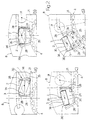
- Figure 1 shows a schematic front view of a first preferred embodiment of the unit according to the present invention;
- Figure 2 shows a schematic front view of a first detail of the Figure 1 unit in different operating positions;
- Figure 3 shows a larger-scale schematic front view of a second detail of the Figure 1 unit in different operating positions;
- Figure 4 shows a larger-scale view in perspective of a third detail of the Figure 1 unit;
- Figure 5 shows a larger-scale schematic front view of the Figure 1 detail in different operating positions;
- Figure 6 shows a schematic front view of a second embodiment of the unit according to the present invention.
-
-
Number 1 in Figure 1 indicates as a whole a transfer unit forming part of a continuous automatic packing machine for producing packets of cigarettes not shown. Onunit 1, agroup 2 of cigarettes is formed (in known manner not shown) inside arespective seat 3 fed continuously and a direction D1 along a path P1 by an endless formingconveyor 4, and is then transferred to acorresponding seat 5 fed continuously and in a direction D2 along a path P2 by an endless wrapping conveyor defined by awrapping wheel 6. - Path P1 is coplanar with path P2, and comprises an initial loading portion P3 at a loading station S1, and a final transfer portion P4 at a transfer station S2 where the
group 2 of cigarettes is transferred by aseat 7 carried by atransmission pulley 8 ofconveyor 4.Seat 7 is a movable seat for receivinggroup 2 fromseat 3 on formingconveyor 4 andfeeding group 2 to thecorresponding seat 5 onwrapping wheel 6. - At transfer station S2,
pulley 8 feeds eachseat 7 along a path substantially coincident with transfer portion P4 of path P1. -
Group 2 is confined within a substantially parallelepiped space defined by a pair of parallel largelateral surfaces 9a, and by a pair of parallel smalllateral surfaces 9b perpendicular tosurfaces 9a. As shown more clearly in Figure 4, said space also comprises two oppositelongitudinal ends 9c, and acentral portion 9d interposed between the twolongitudinal ends 9c. - Along loading portion P3 of path P1,
group 2 is conveyed by formingconveyor 4 with a first orientation with respect to direction D1, and wherein smalllateral surfaces 9b are substantially perpendicular to direction D1; and along path P2,group 2 is conveyed by wrappingwheel 6 with a second orientation with respect to direction D2, and wherein largelateral surfaces 9a are substantially perpendicular to direction D2. When transferred fromconveyor 4 towheel 6,group 2 is obviously rotated 90° about its own longitudinal axis (not shown) parallel to thecigarettes forming group 2. - Before being fed through transfer station S2, each
seat 5 is fed through a supply station (not shown) whereseat 5 receives asheet 10 of foil wrapping material, which is folded into a U insideseat 5, and in which arespective group 2 is wrapped after being transferred tocorresponding seat 5. -
Wrapping wheel 6 comprises acylinder 11 powered to rotate continuously (clockwise in Figure 1) about acentral axis 12 perpendicular to the Figure 1 plane; and a number of peripheral heads 13 (only one shown) equally spaced aboutaxis 12. Eachhead 13 defines arespective seat 5 for first receiving and conveying arespective sheet 10 of wrapping material folded substantially into a U, and for subsequently receiving and conveying arespective group 2 of cigarettes, which is wrapped insheet 10 of wrapping material as the group is fed along path P2. - Each
head 13 is hinged tocylinder 11 and is oscillated about an axis 14 parallel toaxis 12 by a known cam control device 15 (shown schematically in Figure 1); andseat 5 of eachhead 13 is defined by an end wall 16 fitted tohead 13, and by twolateral walls 17, which are hinged to opposite ends of wall 16 and are oscillated, by a control device 19 and about respective axes 18 parallel toaxis 12, between an open and a closed position. - As shown in Figure 1, control device 19 comprises a
slide 19a supporting end wall 16 and which is moved alonghead 13, in a direction perpendicular to end wall 16, by a known cam device (not shown); and twoties 19b, each of which is interposed betweenhead 13 and an intermediate point along a respectivelateral wall 17, so that each axial movement ofslide 19a with respect tohead 13 rotateslateral walls 17 about respective axes 18. - In the open position, the two
lateral walls 17 of eachseat 5 form an obtuse angle with end wall 16, andseat 5 has a section in the form of an isosceles trapezium. In the closed position, the twolateral walls 17 of eachseat 5 substantially form a right angle with end wall 16, andseat 5 has a rectangular section of substantially the same size asgroup 2 so as to engagegroup 2 completely, i.e. at bothcentral portion 9d andlongitudinal ends 9c. - The inner surfaces of
walls 16 and 17 comprise a number of holes (not shown) connected to a known suction device (not shown) carried by wrappingwheel 6. - Each
head 13 also comprises a known folding device orarm 20, which is hinged tohead 13 and oscillated about axis 14 by a known cam device (not shown) to longitudinally fold a projecting portion of asheet 10 of wrapping material folded into a U about arespective group 2 of cigarettes and housed insideseat 5. - Forming
conveyor 4 comprises a known flexible endless toothed belt 21 (shown partly in Figure 1) fed along path P1 (shown partly in Figure 1) bypulley 8, which comprises a toothedcentral roller 22 rotating continuously (anticlockwise in Figure 1) about acentral axis 23 parallel toaxis 12. - Loading station S1 is shown schematically in Figure 1 and, in a first embodiment, is substantially located at the point at which a
complete group 2 of cigarettes is fed to arespective seat 3 by a known forming unit not shown. In a further embodiment,conveyor 4 is a forming conveyor for forminggroups 2, and loading station S1 is substantially located along a portion ofconveyor 4 in which agroup 2 of cigarettes is formed layer by layer inside arespective seat 3 by a known hopper-type forming device (not shown) as described for example in US Patent No. 5,070,991. - Transfer portion P4 of path P1 is located at transfer station S2 and at
pulley 8, and extends substantially along an initial portion of a curved portion of path P1 extending aboutaxis 23. -
Conveyor 4 also comprises a number of heads 24 (only one shown) carried by and equally spaced alongbelt 21. As shown more clearly in Figure 2, eachhead 24 defines arespective seat 3 having a longitudinal dimension (perpendicular to the Figure 2 plane) smaller than that ofgroup 2, and having a rectangular section of substantially the same transverse size asgroup 2, so as to engagegroup 2 bycentral portion 9d while leaving respectivelongitudinal ends 9c substantially free. - Each
head 24 is connected to belt 21 in substantially fixed manner by means of twopins 25, which cooperate withrespective seats 26 onhead 24 to enablehead 24 to move slightly with respect tobelt 21 to adjust to the curved portions of path P1. - Each
head 24 has aretaining device 27 comprising twojaws 28 integral withbelt 21 and which oscillate between a gripping position (as shown for example in Figure 2a) along the straight portions ofbelt 21, and a release position (as shown for example in Figure 2c) along the curved portions (only one shown) ofbelt 21. - In addition to
roller 22,pulley 8 comprises two flanges 29 (only one shown) coaxial withaxis 23 and supporting, in between, a number of peripheral heads 30 (only one shown in Figure 1) equally spaced aboutaxis 23 and mounted for rotation aboutrespective axes 31 parallel toaxis 23. - As shown more clearly in Figures 4 and 5, each
head 30 has apin 32 coaxial withaxis 31 and fitted at opposite ends to twoappendixes 33 ofrespective flanges 29; eachhead 30 comprises twogripping devices 34, which together define arespective seat 7; and eachgripping device 34 comprises two relatively thin L-clamps 35 located in the same plane perpendicular toaxis 31, and movable, with respect to each other and in said plane, between a release position (Figure 5a) and a gripping position (Figure 5b) in whichclamps 35 define a tubular seat 35a having an axis parallel toaxis 31 and a rectangular section of approximately the same size as but no larger than the cross section of agroup 2. Eachgripping device 34 is fitted to arespective rocker arm 36 hinged aboutaxis 31 by acentral sleeve 37 fitted in rotary and axially-sliding manner torespective pin 32. - The angular and axial position of each
sleeve 37 is controlled by an actuating andcontrol device 38, which comprises anarm 39 projecting radially fromsleeve 37 and fitted on the free end with atappet roller 40, which rotates about a respective axis perpendicular toaxis 31 and engages a track 41 formed in a fixed cam 42 located betweenflanges 29 and forming part ofdevice 38. Track 41 extends aboutaxis 23 to control the axial position ofsleeve 37 alongrespective pin 32 alongside variations in the angular position ofrespective seat 7 aboutaxis 23. - Actuating and
control device 38 also comprises, for eachsleeve 37, anarm 43 projecting radially fromsleeve 37; and atappet roller 44 fitted to the free end ofarm 43 to rotate, about a respective axis parallel toaxis 31, along a respective track 45 formed on cam 42 and extending aboutaxis 23 to control the angular position ofsleeve 37 aboutaxis 31 ofrespective pin 32 alongside variations in the angular position ofrespective seat 7 aboutaxis 23. - Each
gripping device 34 also has anactuating device 46 comprising anarticulated parallelogram 47, which in turn comprises twoparallel rods 48 hinged torocker arm 36, and twoparallel rods 49, each fitted at one end with a respective L-clamp 35 ofgripping device 34. One of the tworods 49, indicated 49a, is fitted, on the opposite end to that supportingrespective clamp 35, with atappet roller 50 mounted for rotation, about a respective axis parallel toaxis 31, along a respective track 51 formed on cam 42 and extending aboutaxis 23 to control the axial position ofrod 49a with respect torespective pin 32 alongside variations in the angular position of respective seat aboutaxis 23. - Track 41 of cam 42 is so formed that, as
pulley 8 rotates aboutaxis 23, the tworocker arms 36 of eachseat 7 are moved, alongaxis 31 ofrespective pin 32, between an open position of respective gripping device 34 - wherein the two tubular seats 35a are separated by a distance greater than the length of arespective group 2 of cigarettes - and a closed position of respective gripping device 34 - wherein the two tubular seats 35a definerespective seat 7 and grip and retain arespective group 2 of cigarettes by engagingends 9c ofgroup 2. - Track 45 of cam 42 is so formed that, as
pulley 8 rotates aboutaxis 23, the tworocker arms 36 ofseat 7 are rotated, aboutaxis 31 ofrespective pin 32, between a loading position - whereinseat 7 coincides with arespective seat 3 to remove agroup 2 of cigarettes from seat 3 - and an unloading position - whereinseat 7 coincides with arespective seat 5 to transfergroup 2 toseat 5. - Track 51 of cam 42 is so formed that, as
pulley 8 rotates aboutaxis 23,rod 49a is moved, with respect torespective pin 32, to deform articulatedparallelogram 47 and moveclamps 35 between said gripping and release positions. - Operation of
unit 1 will be described with reference to onegroup 2 of cigarettes, and as of whengroup 2 arrives at station S1. -
Belt 21 moves continuously to feedseat 3 andrespective group 2 of cigarettes along path P1, first along loading portion P3 and then along transfer portion P4 at transfer station S2. - As shown more clearly in Figure 2, as
seat 3 is fed byconveyor 4 along transfer portion P4,gripping devices 34 of acorresponding seat 7 are set bycontrol devices Control device 38 then swingsseat 7 aboutrespective axis 31 to assume and maintain for a given length of time a position substantially coincident with seat 3 (Figure 2b) and whereincontrol devices gripping devices 34 ofseat 7 to said closed and gripping positions togrip group 2. At the same time, the curvature of transfer portion P4moves retaining device 27 ofseat 3 into said release position to leavegroup 2 under the control of seat 7 (Figure 2c). - At this point,
seat 7 is rotated aboutrespective axis 31 to extractgroup 2 from seat 3 (Figure 2d) and feed the group towards acorresponding seat 5, which, as wrappingwheel 6 rotates continuously, is being fed through transfer station S2 (Figure 1) withlateral walls 17 in said open position, and with aU-folded sheet 10 of wrapping material housed and retained inside by said suction device (not shown). - As shown more clearly in Figure 3, in the neighbourhood of transfer station S2,
seat 7 andcorresponding seat 5 are swung aboutrespective axes 31 and 14 byrespective control devices lateral walls 17 ofseat 5 into said closed position to gripgroup 2 and at the sametime finish-fold sheet 10 of wrapping material into a U about group 2 (Figure 3b). - In the Figure 3b position,
seat 5, withsheet 10 of wrapping material in between, engages bothgroup 2 and clamps 35 ofgripping devices 34 ofseat 7, which is made possible by the thinness ofclamps 35. - Once
group 2 is gripped byseat 5,control device 38moves gripping devices 34 ofseat 7 into said open position, so that clamps 35, though still in said gripping position, are withdrawn longitudinally with respect togroup 2 to releasegroup 2. - At this point,
seats control device 38 restoresseat 7 to the initial position. At the same time,folding device 20 ofseat 5 is activated tolongitudinally fold sheet 10 of wrapping material aboutgroup 2, andwrapping wheel 6 rotates continuously to fedseat 5 through successive known folding stations (not shown). - In a further embodiment not shown,
seats 7 are carried by formingconveyor 4 itself, and eachseat 3 is assigned arespective seat 7 fitted toconveyor 4 and adjacent toseat 3. - In a further embodiment shown in Figure 6,
seats 3 on formingconveyor 4 are as described in European Patent Application No. 812,765, and each engage the longitudinal ends of arespective group 2 of cigarettes;seats 3 are carried byrespective forks 52 fitted to belt 21 so as to rotate aboutrespective axes 31 parallel toaxis 23 ofpulley 8; and, along transfer portion P4, a known cam control device (not shown) rotates eachseat 3 aboutrespective axis 31 to transferrespective group 2 to acorresponding seat 5 in exactly the same way as described forseats 7.
Claims (22)
- A method of transferring a group of cigarettes continuously between conveyors, the method comprising a conveying step wherein said group (2) is fed, by means of a first conveyor (4) traveling continuously in a first direction (D1), along a first path (P1) comprising an initial straight loading portion (P3) and a final transfer portion (P4) in a first orientation with respect to said first direction (D1); and a transfer step wherein said group (2) is transferred, as the group (2) travels along said transfer portion (P4), from said first conveyor (4) to a second conveyor (6) traveling continuously in a second direction (D2) along a second path (P2); the method being characterized in that said first path (P1) and said second path (P2) are coplanar; said transfer step being performed by housing the group (2) in said first orientation, at least as the group is fed along said transfer portion (P4), inside a movable seat (7; 3), which is fed by said first conveyor (4) at least along said transfer portion (P4), and is simultaneously moved, with respect to said first conveyor (4) and as the movable seat travels along the transfer portion (P4), between a first position along said first path (P1) and a second position along said second path (P2), so as to effect a rotation of said group (2) from said first orientation with respect to said first direction (D1) to a second orientation with respect to said second direction (D2), whereby the group (2) travels along said straight loading portion (P3) and said second path (P2) with two respective different orientations with respect to said first direction (D1) and said second direction (D2) respectively, said two orientations being substantially at 90° to each other.
- A method as claimed in Claim 1, wherein said first conveyor (4) and said second conveyor (6) comprise a first seat (3) and a second seat (5) respectively for said group (2); said movable seat (7; 3) being said first seat (3), which is fed along said loading portion (P3) in a substantially fixed position with respect to said first conveyor (4), and is moved, along said transfer portion (P4), with respect to the first conveyor (4) to transfer the group (2) to the second seat (5).
- A method as claimed in Claim 1, wherein said first conveyor (4) and said second conveyor (6) comprise a first seat (3) and a second seat (5) respectively for said group (2); said movable seat (7; 3) being a third seat (7), which is fed along said transfer portion (P4) to engage said group (2) housed inside the first seat (3), and is moved with respect to the first seat (3) to remove the group (2) from the first seat (3) and transfer the group (2) to the second seat (5).
- A method as claimed in Claim 2 or 3, wherein said second conveyor (6) is a wrapping conveyor; said second seat (5) housing a sheet (10) of wrapping material folded substantially into a U; and said sheet (10) of wrapping material being fed to said second seat (5) before said group (2) is transferred to the second seat (5).
- A method as claimed in Claim 4, wherein said second seat (5) is defined by an end wall (16), and by two lateral walls (17) movable between an open first position and a closed second position; said two lateral walls (17) being maintained in said first position during transfer of said group (2), and being moved into said second position to hold together said sheet (10) of wrapping material and said group (2).
- A method as claimed in Claim 3, 4 or 5, wherein said third seat (7) is fed along said transfer portion (P4) at a speed substantially equal to the traveling speed of said first seat (3).
- A method as claimed in any one of Claims 1 to 6, wherein said rotation is effected by rotating the group (2) about a first axis (31) movable with the first conveyor (4) along said transfer portion (P4).
- A method as claimed in Claim 7, wherein said group (2) is rotated about said first axis (31) by rotating said movable seat (7; 3) about the first axis (31).
- A method as claimed in any one of Claims 1 to 8, wherein said group (2) is elongated and comprises two opposite longitudinal ends (9c) and a central portion (9d) interposed between said two longitudinal ends (9c); said movable seat (7; 3) engaging the group (2) by said longitudinal ends (9c).
- A method as claimed in Claim 3 and 9, wherein said first seat (3) engages the group (2) by said central portion (9d).
- A method as claimed in Claim 3 and 9, wherein said second seat (5) engages the group (2) by said central portion (9d) and said longitudinal ends (9c).
- A unit for transferring a group of cigarettes continuously between conveyors, the unit comprising a first conveyor (4) for feeding said group (2) continuously and in a first direction (D1) along a first path (P1) comprising an initial straight loading portion (P3) and a final transfer portion (P4) in a first orientation with respect to said first direction (D1) ; a second conveyor (6) for feeding said group (2) continuously and in a second direction (D2) along a second path (P2); and transfer means (30) acting along said transfer portion (P4) to transfer said group (2) from the first conveyor (4) to the second conveyor (6) ; characterized in that said first path (P1) and said second path (P2) are coplanar; said transfer means (30) comprising a movable seat (7; 3) for housing the group (2) in said first orientation and which is fed by said first conveyor (4) at least along said transfer portion (P4); and actuating means (38) for moving said movable seat (7; 3), with respect to the first conveyor (4) and as the movable seat (7; 3) is fed along said transfer portion (P4), between a first position along said first path (P1) and a second position along said second path (P2) to effect a rotation of said group (2) from said first orientation with respect to said first direction (D1) to a second orientation with respect to said second direction (D2), whereby the group (2) travels along said straight loading portion (P3) and said second path (P2) with two respective different orientations with respect to said first direction (D1) and said second direction (D2) respectively, said two orientations being substantially at 90° to each other.
- A unit as claimed in Claim 12, wherein said first conveyor (4) and said second conveyor (6) comprise a first seat (3) and a second seat (5) respectively for said group (2); said movable seat (7; 3) being defined by said first seat (3).
- A unit as claimed in Claim 12, wherein said first conveyor (4) and said second conveyor (6) comprise a first seat (3) and a second seat (5) respectively for said group (2); said first conveyor (4) also comprising a third seat (7) defining said movable seat (7; 3).
- A unit as claimed in Claim 13 or 14, wherein said first conveyor (4) is an output conveyor of a unit for forming said group (2), and said second conveyor (6) is a wrapping wheel.
- A unit as claimed in Claim 13, 14 or 15, wherein second seat (5) is fitted in rotary manner to said second conveyor (6) to rotate about a second axis (14) movable with the second conveyor (6); said second conveyor (6) comprising a first control device (15) for controlling the angular position of said second seat (5) about said second axis (14).
- A unit as claimed in Claim 16, wherein walls (17) movable, with respect to each other, between an open first position and a closed second position; and a second control device (19) for maintaining said two lateral walls (17) in said first position during transfer of said group (2), and for moving said two lateral walls (17) into said second position to retain the group (2) inside the second seat (5).
- A unit as claimed in any one of Claims 12 to 17, wherein said movable seat (7; 3) is fitted to said first conveyor (4) to rotate about the first axis (31); said actuating means (38) controlling the angular position of the movable seat (7; 3) about the first axis (31).
- A unit as claimed in Claim 14 and 18, wherein said first seat (3) is fixed with respect to said first conveyor (4).
- A unit as claimed in Claim 14 and 18, wherein said third seat (7) is defined by two opposite tubular seats (35a), which engage respective longitudinal ends (9c) of said group (2), and are mounted for rotation about said first axis (31).
- A unit as claimed in Claim 20, wherein said tubular seats (35a) are so mounted as to slide, in a third direction parallel to said first axis (31), between an open position and a closed position; said actuating means (38) controlling the position of said tubular seats (35a) in said third direction and between said open position and said closed position.
- A unit as claimed in Claim 21, wherein each said tubular seat (35a) is defined by a respective gripping device (34) comprising two L-shaped clamps (35) movable with respect to each other between a gripping position, in which the clamps (35) are substantially joined to each other to define the respective tubular seat (35a), and a release position, in which the clamps (35) are separated by a given distance; said transfer means (30) comprising a third control device (46) for controlling the position, between said release position and said gripping position, of each of said clamps (35) with respect to the corresponding other clamp (35).
Applications Claiming Priority (2)
| Application Number | Priority Date | Filing Date | Title |
|---|---|---|---|
| IT98BO000127A IT1299878B1 (en) | 1998-03-05 | 1998-03-05 | METHOD AND UNIT FOR THE CONTINUOUS TRANSFER OF A GROUP OF CIGARETTES BETWEEN CONVEYORS. |
| ITBO980127 | 1998-03-05 |
Publications (2)
| Publication Number | Publication Date |
|---|---|
| EP0940340A1 EP0940340A1 (en) | 1999-09-08 |
| EP0940340B1 true EP0940340B1 (en) | 2001-08-22 |
Family
ID=11342975
Family Applications (1)
| Application Number | Title | Priority Date | Filing Date |
|---|---|---|---|
| EP99104386A Expired - Lifetime EP0940340B1 (en) | 1998-03-05 | 1999-03-04 | Method and unit for transferring a group of cigarettes continuously between conveyors |
Country Status (7)
| Country | Link |
|---|---|
| US (1) | US6186313B1 (en) |
| EP (1) | EP0940340B1 (en) |
| DE (1) | DE69900221T2 (en) |
| ES (1) | ES2162500T3 (en) |
| IT (1) | IT1299878B1 (en) |
| PT (1) | PT940340E (en) |
| RU (1) | RU2228886C2 (en) |
Families Citing this family (18)
| Publication number | Priority date | Publication date | Assignee | Title |
|---|---|---|---|---|
| GB9706984D0 (en) * | 1997-04-05 | 1997-05-21 | Molins Plc | Article handling apparatus |
| GB9713012D0 (en) * | 1997-06-19 | 1997-08-27 | Molins Plc | Package folding apparatus |
| US6748995B2 (en) * | 2000-08-24 | 2004-06-15 | Radio Frequency Services, Inc. | Apparatus and method for manufacturing panels from wood pieces |
| ITPR20010050A1 (en) * | 2001-07-31 | 2003-01-31 | Sig Simonazzi Beverage S P A | CLAMP, IN PARTICULAR FOR HOLDING CONTAINERS. |
| FR2831147B1 (en) * | 2001-10-19 | 2004-02-06 | Leroux Gilles Sa | TRANSPORT DEVICE IN A CARD EMBOSSING SYSTEM |
| ITBO20010752A1 (en) * | 2001-12-12 | 2003-06-12 | Gd Spa | WASTE TRANSFER METHOD AND UNIT |
| US6789370B2 (en) | 2001-12-18 | 2004-09-14 | G.D Societa' Per Azioni | Cigarette packing machine |
| US7051861B2 (en) | 2002-06-12 | 2006-05-30 | Ocean Spray Cranberries, Inc. | Conveying system |
| ITBO20030249A1 (en) * | 2003-04-29 | 2004-10-30 | Gd Spa | WRAPPING METHOD OF ORDERED GROUPS OF CIGARETTES. |
| NL1023908C2 (en) * | 2003-07-11 | 2005-01-12 | Cfs Weert Bv | Transfer. |
| SE526217C2 (en) * | 2003-12-16 | 2005-08-02 | Tetra Laval Holdings & Finance | Device for pushing packaging containers |
| DE102005059620A1 (en) * | 2005-12-12 | 2007-06-14 | Focke & Co.(Gmbh & Co. Kg) | Device for producing packages with shrink film |
| ITBO20060516A1 (en) * | 2006-07-04 | 2006-10-03 | Gd Spa | METHOD FOR THE TRANSFER OF CIGARETTE GROUPS IN A CIGARETTE PACKAGING MACHINE. |
| EP2746170B1 (en) * | 2012-12-21 | 2016-04-27 | Tetra Laval Holdings & Finance S.A. | Folding unit for pourable food product packaging machines |
| DE102013103310A1 (en) * | 2013-04-03 | 2014-10-09 | Khs Gmbh | Transport device for container treatment machines |
| DE102014010422A1 (en) * | 2014-07-16 | 2016-01-21 | Focke & Co. (Gmbh & Co. Kg) | Method and device for producing (cigarette) packages |
| WO2016174530A1 (en) * | 2015-04-30 | 2016-11-03 | Fillshape S.R.L. | System and method for transferring pouches |
| GB201821302D0 (en) * | 2018-12-31 | 2019-02-13 | British American Tobacco Investments Ltd | Apparatus and method for packaging tobacco industry products |
Family Cites Families (24)
| Publication number | Priority date | Publication date | Assignee | Title |
|---|---|---|---|---|
| US2822653A (en) * | 1954-02-19 | 1958-02-11 | Zinn | Apparatus for closing and sealing containers |
| US3545172A (en) | 1966-11-11 | 1970-12-08 | Arenco Ab | Cigarette packeting machine |
| GB1459091A (en) * | 1973-02-16 | 1976-12-22 | Molins Ltd | Packing machines |
| DE2949252A1 (en) * | 1979-12-07 | 1981-06-11 | Focke & Co, 2810 Verden | METHOD AND DEVICE FOR PACKING CIGARETTES OR THE LIKE |
| CH641416A5 (en) * | 1979-12-13 | 1984-02-29 | Sig Schweiz Industrieges | DEVICE ON A PACKAGING MACHINE FOR FORMING URGENT GROUPS OF DISC-SHAPED OBJECTS. |
| FR2607479B1 (en) * | 1986-12-01 | 1991-02-15 | Remy & Cie E P | DEVICE FOR GRIPPING AND RETAINING OBJECTS, SUCH AS FOR example CONTAINERS, ON A CONVEYOR, AND CONVEYOR PROVIDED WITH SUCH A DEVICE |
| DE3861493D1 (en) * | 1987-06-19 | 1991-02-14 | Hauni Werke Koerber & Co Kg | METHOD AND DEVICE FOR PACKING ROD-SHAPED ITEMS OF THE TOBACCO-PROCESSING INDUSTRY. |
| GB8718085D0 (en) | 1987-07-30 | 1987-09-03 | Molins Plc | Forming groups of rod-like articles |
| CH675114A5 (en) * | 1988-02-02 | 1990-08-31 | Elpatronic Ag | |
| IT1245763B (en) * | 1991-02-11 | 1994-10-14 | Gd Spa | DEVICE FOR THE TRANSFER OF CIGARETTES OF CIGARETTE FROM A DOUBLE WHEEL PACKAGING MACHINE TO A FILTER FEEDING MACHINE. |
| US5199547A (en) * | 1991-07-29 | 1993-04-06 | G.D. Societa' Per Azioni | Method and device for unloading products off a continuously-moving conveyor |
| US5299679A (en) | 1991-12-25 | 1994-04-05 | Japan Tobacco Inc. | Apparatus for piling and transferring cigarettes |
| US5442894A (en) * | 1992-01-28 | 1995-08-22 | Tokyo Automatic Machinery Works, Ltd. | Packaging device |
| IT1257763B (en) * | 1992-03-13 | 1996-02-13 | Gd Spa | POCKET ELEMENT FOR A WRAPPING WHEEL OF A CIGARETTE PACKING MACHINE |
| US5465952A (en) * | 1993-02-17 | 1995-11-14 | Ferag Ag | Gripper for a conveying device for conveying single-sheet or multiple-sheet printed products |
| JP3308374B2 (en) * | 1994-01-18 | 2002-07-29 | 日本たばこ産業株式会社 | Article removal and alignment equipment |
| US5551334A (en) * | 1994-09-29 | 1996-09-03 | Dec International, Inc. | Pasteurizer |
| IT1281205B1 (en) * | 1995-02-15 | 1998-02-17 | Sasib Spa | CORNER CONVEYOR FOR DELICATE ASTIFORM OR SIMILAR OBJECTS, IN PARTICULAR IN CIGARETTE PACKAGING MACHINES. |
| IT1280369B1 (en) * | 1995-02-21 | 1998-01-20 | Gd Spa | CONTINUOUS CIGARETTE PACKING MACHINE |
| US5697490A (en) * | 1995-08-15 | 1997-12-16 | Raque Food Systems, Inc. | Clamshell carrier |
| IT1285579B1 (en) * | 1996-03-01 | 1998-06-18 | Gd Spa | OUTPUT UNIT FOR A CONTINUOUS WRAPPING MACHINE |
| IT1285911B1 (en) * | 1996-04-30 | 1998-06-26 | Gd Spa | PRODUCT CONVEYOR DEVICE |
| IT1290634B1 (en) * | 1997-01-10 | 1998-12-10 | Gd Spa | PACKAGE WRAPPING METHOD AND UNIT. |
| IT1294188B1 (en) * | 1997-09-04 | 1999-03-22 | Gd Spa | PACKAGING MACHINE. |
-
1998
- 1998-03-05 IT IT98BO000127A patent/IT1299878B1/en active IP Right Grant
-
1999
- 1999-03-04 PT PT99104386T patent/PT940340E/en unknown
- 1999-03-04 EP EP99104386A patent/EP0940340B1/en not_active Expired - Lifetime
- 1999-03-04 RU RU99104301/12A patent/RU2228886C2/en not_active IP Right Cessation
- 1999-03-04 DE DE69900221T patent/DE69900221T2/en not_active Expired - Fee Related
- 1999-03-04 ES ES99104386T patent/ES2162500T3/en not_active Expired - Lifetime
- 1999-03-04 US US09/262,442 patent/US6186313B1/en not_active Expired - Fee Related
Also Published As
| Publication number | Publication date |
|---|---|
| ITBO980127A1 (en) | 1999-09-05 |
| RU2228886C2 (en) | 2004-05-20 |
| ES2162500T3 (en) | 2001-12-16 |
| DE69900221T2 (en) | 2002-05-02 |
| ITBO980127A0 (en) | 1998-03-05 |
| PT940340E (en) | 2002-01-30 |
| DE69900221D1 (en) | 2001-09-27 |
| IT1299878B1 (en) | 2000-04-04 |
| US6186313B1 (en) | 2001-02-13 |
| EP0940340A1 (en) | 1999-09-08 |
Similar Documents
| Publication | Publication Date | Title |
|---|---|---|
| EP0940340B1 (en) | Method and unit for transferring a group of cigarettes continuously between conveyors | |
| EP1059236B1 (en) | Method and machine for wrapping a product in a sheet of heat-seal wrapping material | |
| EP0608823B2 (en) | Wrapping machine, particularly for food products such as sweets and similar | |
| EP0940339B1 (en) | Continuous product wrapping method and machine | |
| EP1052171B1 (en) | Method and device for feeding groups of cigarettes to a continuous wrapping line of a packing machine | |
| EP0795473A1 (en) | Product overwrapping machine | |
| US6286291B1 (en) | Method and machine for wrapping a product | |
| EP0936143B1 (en) | Method and machine for packing a product | |
| EP0900731B1 (en) | Packing machine | |
| EP0769453B1 (en) | Continuous product wrapping method | |
| EP0972706A1 (en) | Packaging machine for wrapping a product | |
| EP0895722B2 (en) | Method for transferring articles | |
| CN112739224B (en) | Device for transferring rod-shaped articles used in the tobacco industry | |
| EP1013557B1 (en) | Method of feeding collars to a continuous packing line for producing rigid packets of cigarettes | |
| EP0936163A1 (en) | Method of transferring articles | |
| US5794413A (en) | Product overwrapping method | |
| CN1136122C (en) | Method and unit for transferring group of cigarettes continuously between conveyors | |
| EP0795474B1 (en) | Product overwrapping method | |
| US6655113B2 (en) | Method and unit for wrapping sweets | |
| EP1106549B1 (en) | Method and device for feeding sheets to a wrapping line |
Legal Events
| Date | Code | Title | Description |
|---|---|---|---|
| PUAI | Public reference made under article 153(3) epc to a published international application that has entered the european phase |
Free format text: ORIGINAL CODE: 0009012 |
|
| AK | Designated contracting states |
Kind code of ref document: A1 Designated state(s): DE ES FR GB IT PT |
|
| AX | Request for extension of the european patent |
Free format text: AL;LT;LV;MK;RO;SI |
|
| 17P | Request for examination filed |
Effective date: 20000215 |
|
| AKX | Designation fees paid |
Free format text: DE ES FR GB IT PT |
|
| GRAG | Despatch of communication of intention to grant |
Free format text: ORIGINAL CODE: EPIDOS AGRA |
|
| 17Q | First examination report despatched |
Effective date: 20001128 |
|
| GRAG | Despatch of communication of intention to grant |
Free format text: ORIGINAL CODE: EPIDOS AGRA |
|
| GRAH | Despatch of communication of intention to grant a patent |
Free format text: ORIGINAL CODE: EPIDOS IGRA |
|
| GRAH | Despatch of communication of intention to grant a patent |
Free format text: ORIGINAL CODE: EPIDOS IGRA |
|
| GRAA | (expected) grant |
Free format text: ORIGINAL CODE: 0009210 |
|
| AK | Designated contracting states |
Kind code of ref document: B1 Designated state(s): DE ES FR GB IT PT |
|
| REF | Corresponds to: |
Ref document number: 69900221 Country of ref document: DE Date of ref document: 20010927 |
|
| ET | Fr: translation filed | ||
| REG | Reference to a national code |
Ref country code: ES Ref legal event code: FG2A Ref document number: 2162500 Country of ref document: ES Kind code of ref document: T3 |
|
| REG | Reference to a national code |
Ref country code: GB Ref legal event code: IF02 |
|
| REG | Reference to a national code |
Ref country code: PT Ref legal event code: SC4A Free format text: AVAILABILITY OF NATIONAL TRANSLATION Effective date: 20011018 |
|
| PLBE | No opposition filed within time limit |
Free format text: ORIGINAL CODE: 0009261 |
|
| STAA | Information on the status of an ep patent application or granted ep patent |
Free format text: STATUS: NO OPPOSITION FILED WITHIN TIME LIMIT |
|
| 26N | No opposition filed | ||
| PGFP | Annual fee paid to national office [announced via postgrant information from national office to epo] |
Ref country code: PT Payment date: 20040225 Year of fee payment: 6 Ref country code: GB Payment date: 20040225 Year of fee payment: 6 |
|
| PGFP | Annual fee paid to national office [announced via postgrant information from national office to epo] |
Ref country code: FR Payment date: 20040318 Year of fee payment: 6 |
|
| PGFP | Annual fee paid to national office [announced via postgrant information from national office to epo] |
Ref country code: ES Payment date: 20040407 Year of fee payment: 6 |
|
| PGFP | Annual fee paid to national office [announced via postgrant information from national office to epo] |
Ref country code: DE Payment date: 20040430 Year of fee payment: 6 |
|
| PG25 | Lapsed in a contracting state [announced via postgrant information from national office to epo] |
Ref country code: IT Free format text: LAPSE BECAUSE OF NON-PAYMENT OF DUE FEES Effective date: 20050304 Ref country code: GB Free format text: LAPSE BECAUSE OF NON-PAYMENT OF DUE FEES Effective date: 20050304 |
|
| PG25 | Lapsed in a contracting state [announced via postgrant information from national office to epo] |
Ref country code: ES Free format text: LAPSE BECAUSE OF NON-PAYMENT OF DUE FEES Effective date: 20050305 |
|
| PG25 | Lapsed in a contracting state [announced via postgrant information from national office to epo] |
Ref country code: PT Free format text: LAPSE BECAUSE OF NON-PAYMENT OF DUE FEES Effective date: 20050905 |
|
| PG25 | Lapsed in a contracting state [announced via postgrant information from national office to epo] |
Ref country code: DE Free format text: LAPSE BECAUSE OF NON-PAYMENT OF DUE FEES Effective date: 20051001 |
|
| REG | Reference to a national code |
Ref country code: PT Ref legal event code: MM4A Effective date: 20050905 |
|
| GBPC | Gb: european patent ceased through non-payment of renewal fee |
Effective date: 20050304 |
|
| PG25 | Lapsed in a contracting state [announced via postgrant information from national office to epo] |
Ref country code: FR Free format text: LAPSE BECAUSE OF NON-PAYMENT OF DUE FEES Effective date: 20051130 |
|
| REG | Reference to a national code |
Ref country code: FR Ref legal event code: ST Effective date: 20051130 |
|
| REG | Reference to a national code |
Ref country code: ES Ref legal event code: FD2A Effective date: 20050305 |