EP0940232B1 - Klauenkupplung für eine Kettensäge - Google Patents
Klauenkupplung für eine Kettensäge Download PDFInfo
- Publication number
- EP0940232B1 EP0940232B1 EP99301334A EP99301334A EP0940232B1 EP 0940232 B1 EP0940232 B1 EP 0940232B1 EP 99301334 A EP99301334 A EP 99301334A EP 99301334 A EP99301334 A EP 99301334A EP 0940232 B1 EP0940232 B1 EP 0940232B1
- Authority
- EP
- European Patent Office
- Prior art keywords
- gear
- dog clutch
- engaging mechanism
- chain
- actuator
- Prior art date
- Legal status (The legal status is an assumption and is not a legal conclusion. Google has not performed a legal analysis and makes no representation as to the accuracy of the status listed.)
- Expired - Lifetime
Links
- 230000007246 mechanism Effects 0.000 title claims description 42
- 241000282472 Canis lupus familiaris Species 0.000 claims description 55
- 230000002093 peripheral effect Effects 0.000 claims description 12
- 239000002184 metal Substances 0.000 description 10
- 230000009471 action Effects 0.000 description 6
- 230000000994 depressogenic effect Effects 0.000 description 5
- 239000000463 material Substances 0.000 description 4
- 238000010586 diagram Methods 0.000 description 2
- 238000004519 manufacturing process Methods 0.000 description 2
- 230000001133 acceleration Effects 0.000 description 1
- 230000004913 activation Effects 0.000 description 1
- 238000002485 combustion reaction Methods 0.000 description 1
- 238000010276 construction Methods 0.000 description 1
- 230000000881 depressing effect Effects 0.000 description 1
- 231100001261 hazardous Toxicity 0.000 description 1
- 230000003993 interaction Effects 0.000 description 1
- 238000000034 method Methods 0.000 description 1
- 230000008569 process Effects 0.000 description 1
- 230000004044 response Effects 0.000 description 1
- 230000001960 triggered effect Effects 0.000 description 1
Images


Classifications
-
- B—PERFORMING OPERATIONS; TRANSPORTING
- B27—WORKING OR PRESERVING WOOD OR SIMILAR MATERIAL; NAILING OR STAPLING MACHINES IN GENERAL
- B27B—SAWS FOR WOOD OR SIMILAR MATERIAL; COMPONENTS OR ACCESSORIES THEREFOR
- B27B17/00—Chain saws; Equipment therefor
- B27B17/08—Drives or gearings; Devices for swivelling or tilting the chain saw
- B27B17/10—Transmission clutches specially designed for chain saws
-
- F—MECHANICAL ENGINEERING; LIGHTING; HEATING; WEAPONS; BLASTING
- F16—ENGINEERING ELEMENTS AND UNITS; GENERAL MEASURES FOR PRODUCING AND MAINTAINING EFFECTIVE FUNCTIONING OF MACHINES OR INSTALLATIONS; THERMAL INSULATION IN GENERAL
- F16D—COUPLINGS FOR TRANSMITTING ROTATION; CLUTCHES; BRAKES
- F16D11/00—Clutches in which the members have interengaging parts
- F16D11/14—Clutches in which the members have interengaging parts with clutching members movable only axially
-
- F—MECHANICAL ENGINEERING; LIGHTING; HEATING; WEAPONS; BLASTING
- F16—ENGINEERING ELEMENTS AND UNITS; GENERAL MEASURES FOR PRODUCING AND MAINTAINING EFFECTIVE FUNCTIONING OF MACHINES OR INSTALLATIONS; THERMAL INSULATION IN GENERAL
- F16D—COUPLINGS FOR TRANSMITTING ROTATION; CLUTCHES; BRAKES
- F16D23/00—Details of mechanically-actuated clutches not specific for one distinct type
- F16D23/12—Mechanical clutch-actuating mechanisms arranged outside the clutch as such
-
- F—MECHANICAL ENGINEERING; LIGHTING; HEATING; WEAPONS; BLASTING
- F16—ENGINEERING ELEMENTS AND UNITS; GENERAL MEASURES FOR PRODUCING AND MAINTAINING EFFECTIVE FUNCTIONING OF MACHINES OR INSTALLATIONS; THERMAL INSULATION IN GENERAL
- F16D—COUPLINGS FOR TRANSMITTING ROTATION; CLUTCHES; BRAKES
- F16D11/00—Clutches in which the members have interengaging parts
- F16D2011/008—Clutches in which the members have interengaging parts characterised by the form of the teeth forming the inter-engaging parts; Details of shape or structure of these teeth
-
- F—MECHANICAL ENGINEERING; LIGHTING; HEATING; WEAPONS; BLASTING
- F16—ENGINEERING ELEMENTS AND UNITS; GENERAL MEASURES FOR PRODUCING AND MAINTAINING EFFECTIVE FUNCTIONING OF MACHINES OR INSTALLATIONS; THERMAL INSULATION IN GENERAL
- F16D—COUPLINGS FOR TRANSMITTING ROTATION; CLUTCHES; BRAKES
- F16D23/00—Details of mechanically-actuated clutches not specific for one distinct type
- F16D23/12—Mechanical clutch-actuating mechanisms arranged outside the clutch as such
- F16D2023/123—Clutch actuation by cams, ramps or ball-screw mechanisms
Definitions
- the present invention relates to a dog clutch for a power tool and in particular, to a dog clutch for a chain saw.
- a clutch according to the preamble of independent claim 1 is known from US 5 709 032 A.
- a chain saw comprises a cutting chain which is driven around a chain bar by a motor.
- the motor can be either an internal combustion engine or an electric motor.
- the chain saw is supported by an operator in use by two handles, a first rear handle located at the rear of the main body of the chain saw and a second bail handle located on the side of the main body of the chain saw.
- Chain saws are commonly constructed so that the chain is driven by the motor via a clutch.
- the pivotal handle When the pivotal handle is pivoted forward due to "kick-back", the movement of the pivotal handle guard interacts with the clutch in order to disengage the clutch allowing the chain to run to a halt due to friction generated between the chain and the chain bar.
- a known type of such a clutch mechanisms that of a dog clutch.
- known designs of dog clutch are complicated. They are often difficult to machine and therefore expensive to manufacture. Furthermore, they are bulky, taking up substantial and valuable space within the chain saw.
- a common type of brake is that of a band brake.
- the addition of such brakes further complicates the design increasing costs and size.
- a dog clutch for a power tool comprising a first gear mounted on and a rotatable spindle, a second gear rotatably mounted adjacent the first gear and expresseded towards the first gear, and an engaging mechanism in which the first gear (32) is attached to the rotatable spindle (34); the second gear is rotatably mounted on and axially slidable along the spindle, and the engaging mechanism is rotatably mounted adjacent to the second gear about and axially slidable along the longitudinal axis of the spindle and is configured so that rotational movement of the engaging mechanism translates into an axial sliding movement of the engaging mechanism wherein rotational movement of the engaging mechanism moves the second gear into and out of a driving engagement with the first gear depending on the direction of rotation.
- the engaging mechanism comprises a cam ring having a plurality of cam surfaces which co-operate with corresponding surfaces to translate rotational movement of the cam ring into an axial sliding movement of the cam ring.
- the engaging mechanism is rotatably mounted on the second gear.
- the size of the clutch is further reduced and the design of clutch is further compacted.
- it provides a simple and easy way of mounting the engaging mechanism within the dog clutch.
- the second gear can be biased towards the first gear by a helical spring.
- the engaging mechanism is mounted in an axially slidable but non-rotatable fashion within a gear actuator which is capable of pivoting about the longitudinal axis of the spindle between a first position where the second gear drivingly engages the first gear and a second position where the second gear is disengaged from the first gear.
- the gear actuator By mounting the engaging mechanism within the gear actuator so that it is able to axially slide within the gear actuator, but is unable to rotate relative to the gear actuator, the gear actuator only needs to move in a pivotal motion only to engage or disengage the dog clutch. Therefore, this permits a simple interconnection between the dog clutch and to separate switching mechanisms. Switch mechanisms are able to be connected to the gear actuator so that movement of the switching mechanisms pivotally move the gear actuator to engage or disengage the dog clutch. Furthermore, the design of dog clutch is kept compact by concentrically mounting the gear actuator about the engaging mechanism.
- the gear actuator can be biased, for instance, by a helical spring, towards the second position, the biasing force being of a sufficient strength to overcome the biasing force which biases the second gear towards driving engagement with the first gear. This ensures that the dog clutch is biased towards disengagement.
- the first gear can comprise an outer peripheral surface which meshes with a series of ramped dogs on the second gear, when the second gear drivingly engages the first gear.
- ramped dogs on the second gear allows the gears to continue to rotate relative to each other if the two gears are not aligned, because the ramped dogs are able to slide smoothly until they become aligned with the peripheral surface at which point the ramped dogs will drivingly mesh with the peripheral surface, thus preventing relative rotation movement between gears. This prevents damage to the gears during engagement.
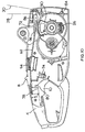
- the chain saw comprises a central body portion (generally indicated by reference number (2)) having a rear handle (4) attached to the rear of the central body portion (2), a sliding switch (8) mounted on the top of the rear handle (4), a trigger switch (10) mounted in the central aperture formed by the rear handle (4), a chain tensioner (not shown) which moves a chain bar (12) (indicated by the dashed lines in Figure 1) to tighten a cutting chain (not shown) which runs around the chain bar (12) in a known way and which is operated by the rotation of a knob (14), an electric motor (not shown) which drives the chain saw and which is housed in a hood (18), a front bail handle (20) attached to the side of the central body portion (2) in front of the hood (18) and a pivotal handle guard (22) which pivots about the base portion (24) of the front bail handle (20) about a substantially horizontal axis of pivot.
- a central body portion generally indicated by reference number (2)
- a sliding switch (8) mounted on the top of the rear handle
- the electric motor drives the chain of the chain saw via a clutch mechanism.
- the electric motor rotatingly drives the clutch mechanism which, when engaged, rotatingly drives a sprocket (not shown) around which is wrapped part of the chain.
- the clutch mechanism is biased by a spring (26) towards the disengaged position.
- the clutch mechanism is engaged or disengaged by the movement of the sliding switch (8) which is linked mechanically to the clutch mechanism.
- the clutch mechanism is engaged by sliding the sliding switch (8) forward to a forward position and disengaged by allowing the sliding switch to slide back due to a biasing force to a rearward position.
- the sliding switch (8) is further configured so that the trigger switch (10) cannot be depressed, thereby preventing the flow of electrical current to the electric motor, until the sliding switch (8) is in the forward position.
- the clutch mechanism is further linked to the pivotal handle guard (22).
- the pivotal handle guard (22) During the normal course of operation of the chain saw the pivotal handle guard (22) remains in a rear position (indicated by line 28 in Figures 10,11,17) towards the bail handle (20). Whilst the pivotal handle guard (22) is in this position, it has no interaction with the clutch mechanism thereby allowing the normal operation of the clutch mechanism and hence chain saw.
- the pivotal handle guard (22) is pivoted to a forward position (indicated by line 30)
- the movement disengages the sliding switch (8) from the clutch mechanism thereby allowing the clutch mechanism to disengage due to the biasing force of the spring (21).
- the forward pivotal movement of the pivotal handle guard (22) most often occurs when the chain saw "kicks back" whilst being used.
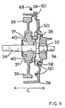
- the clutch mechanism is of the dog clutch variety and comprises a first driven gear (32) which is mounted on and rigidly attached to a rotatably mounted driven spindle (34), a second drive gear (36) which is rotatably mounted on and axially slidable along the driven spindle (34) adjacent to the driven gear (32) and a cam ring (38) which is rotatably mounted within a limited range of rotation about the drive gear (36).
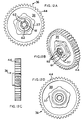
- Figure 12 shows a detailed design drawing of the drive gear (36).
- the drive gear (36) is manufactured from two component parts, an inner part (37) around which is formed an outer cog wheel (39).
- FIG 13 shows a detailed drawing of the driven gear (32) mounted of the driven spindle (34) and Figure 15 shows a detailed design drawing of the cam ring (38).
- the drive gear (36) is biased towards the driven gear (32) by a spring (40) which is located between the drive gear (36) and a wall (42) of the casing for the dog clutch.
- the outer circumference (44) of the drive gear (36) meshes with a gear (46) rigidly mounted on a rotatable drive spindle (48) of the electric motor. As the drive spindle (48) rotates about its axis, the gear (46) rotates which in turn causes the drive gear (36) to rotate.
- the sprocket is mounted on the driven spindle (34) which drives the chain of the chain saw (not shown).
- the cam ring (38) is mounted within a gear actuator (50) as shown more clearly in Figures 10 and 11.
- Figure 14 shows a detailed design drawing for the gear actuator (50).
- Three teeth (52) on the gear actuator (50) project into three corresponding slots (54) on the cam ring (38) so that the gear actuator (50) and the cam ring (38) pivot in unison.
- the cam ring (38) is able to slide axially within the gear actuator (50) in the direction indicated by Arrow C shown in Figures 5, 7 and 9.
- the drive gear (36) which is biased towards the driven gear (32) by the spring (40), biases the cam ring (38) towards a wall (56) of the casing of the dog clutch.
- a recess (61) which comprises a plurality of ramped dogs (62) which mesh with the corresponding peripheral surface (64) on the driven gear (32).
- Figures 12 and Figure 13 show the drive gear (36) and the driven gear (32) respectively in detail.
- Ramped dogs (as opposed to teeth or castellations) have been used on the drive gear (36) so that, if they engage with the peripheral surface (64) of the driven gear (32) when they are not aligned, as the drive gear (36) is rotated, the ramped dogs will slide smoothly into alignment and then mesh with the peripheral surface (64).
- a spring (26) biases the gear actuator (50) and hence the cam ring (38) to rotate in an anti-clockwise direction to cause the ramps (60) on the cam ring (38) to ride up the ramps on the wall (56) of the casing to their fullest extent, disengaging the ramped dogs (62) on the drive gear (36) from the peripheral surface (64) of the driven gear (32).
- the biasing force of the spring (26) is sufficient to override the biasing force of the spring (40) biasing the drive gear (36) against the driven gear (32).
- the gear actuator (50) is manually pivoted against the biasing force of the spring (26) by a user sliding a sliding switch (8) mounted on the top of the rear handle (4) of the chain saw.
- the sliding switch (8) is connected to the gear actuator (50) via a metal rod (68) which connects with a groove (70) in the top (72) of the gear actuator (50).
- the sliding switch (8) is biased towards the rear of the rear handle (4) by the gear actuator (50) via the metal rod (68) due to the biasing force of the spring (26), as shown in Figure 10.
- the gear actuator (50) and hence the cam ring (38) pivot against the biasing force of the spring (26) as shown in Figure 11.
- the trigger switch (10) is pivotably mounted on the inside of the handle (4).
- the trigger switch (10) activates the electrical power supply to the electric motor (16) by engaging an electrical switch (74).
- a spring biases the trigger switch (10) away from the electrical switch (74).
- the end (76) of the trigger switch (10) engages the electrical switch (74) as shown in Figure 11.
- the sliding switch (8) and the trigger switch (10) are configured so that they interact with each other.
- the trigger switch (10) is biased away from the electrical switch (74) and the sliding switch (8) is biased towards the rear of the rear handle (4) of the chain saw, as shown in Figure 10.
- the sliding switch (8) is in its rest position ( Figure 10) a ledge (78) of the sliding switch (8) abuts ledge (80) of the trigger switch (10) and hence prevents the trigger switch (10) from being depressed to actuate the electrical switch (74).
- the sliding switch (8) has to be moved forwards, for the ledge (78) to be removed from the path of the ledge (80) in order for a user to activate the electrical switch (74) by depressing the trigger switch (10), as shown in Figure 11.
- the trigger switch (10) is depressed, the front (82) of the ledge (80) moves into the path of the ledge (78) of the sliding switch (8) and thus prevents the sliding switch (8) from sliding back whilst the trigger switch (10) is depressed.
- This arrangement ensures that a user engages the dog clutch using the sliding switch (8) prior to applying electrical power to the electric motor (16) using the trigger switch (10).
- the dog clutch is designed to interact with a pivotal handle guard (22) which is mounted on the front bail handle (20) of the chain saw.
- the handle guard (22) pivots about a point (84) between two positions indicated by the two lines (28) and (30).
- the axis of pivot which projects perpendicularly to the plane of drawings of Figures 10, 11 and 17 through point (84) of the handle guard (22) is parallel to that of the driven spindle (34).
- the handle guard (22) is a safety feature of the chain saw. In normal use, the handle guard (22) is positioned in the position indicated by the line (28). During the normal operation of the chain saw, the handle guard remains in this position at all times. However, sometimes the chain saw, in use, will "kick back".
- the blade of the chain saw is thrown vertically upwards towards the head of the user.
- the chain saw's acceleration is very great and either the inertia of the handle guard (22) or the back of the hand of the user holding the bail handle (30) hits the pivotal handle guard (22 causes it to pivot to the position indicated by the line (30).
- the dog clutch is configured so that the pivotal movement of the pivotal handle guard (22) from position (28) to (30) causes the dog clutch to disengage the chain from the electric motor and hence to stop the chain regardless of the position of the sliding switch (8).
- a guard actuator (86) is rigidly attached to the handle guard (22).
- the shape of the guard actuator (86) is shown in Figure 1,2,3.
- the end of the metal rod (68) is bent at 90° to form a peg which sits in and passes through the groove (70) of the gear actuator (50).
- Above the groove (70) is a slot (90) which communicates with the groove (70).
- the peg remains in the groove (70).
- the peg passes through the groove (70) and projects outwardly to the side of the gear actuator (50) as shown in Figure 6.
- An arm (92) of the guard actuator (86) is positioned below the peg during normal use. During normal use of the chain saw the gear actuator (50) is pivoted under the action of the metal rod (68).
- the guard actuator (86) moves about the point (84). As it does so, the arm (92) of the guard actuator (86) knocks the peg out of the groove (70) and into the slot (90) as shown in Figure 11.
- the gear actuator (50) pivots back under the biasing action of the spring (40), the peg sliding along the slot (90) as it does so.
- the pivoting action of the gear actuator (50) causes the dog clutch to become disengaged, this disengages the drive to the chain which will soon run down to a stop. This is a safety feature which disengages the chain when kick back occurs.
- the spring (96) makes contact with and biases the metal rod (68) towards the driven spindle 34) when the dog clutch is disengaged so that the peg (88) is biased into the groove (70) regardless of the orientation of the chain saw.
- the handle guard (32) is in a position indicated by line (30) the gear actuator (50) is prevented from pivoting in response to movement of the sliding switch (8) because the peg is blocked by the arm (92) of the guard actuator (86). Therefore, the pivotal handle guard (22) has to be returned to the position indicated by line (28) so that it is below the level of the groove (70) so that the peg formed by the metal rod (68) can fall back into the groove (70) under the action of the spring (96). Only when the handle guard has been set in position (28) can the clutch be engaged using the sliding switch (8) in order to drive the chain.
Landscapes
- Engineering & Computer Science (AREA)
- General Engineering & Computer Science (AREA)
- Mechanical Engineering (AREA)
- Life Sciences & Earth Sciences (AREA)
- Wood Science & Technology (AREA)
- Forests & Forestry (AREA)
- Sawing (AREA)
Claims (8)
- Klauenkupplung für ein kraftgetriebenes Werkzeug, aufweisend ein auf einer drehbaren Spindel (34) befestigtes erstes Zahnrad (32);
ein drehbar benachbart zum ersten Zahnrad (32) befestigtes und in Richtung auf dieses federbelastetes zweites Zahnrad (36) und
einen Eingriffsmechanismus (38), dadurch gekennzeichnet, dass das erste Zahnrad (32) an der drehbaren Spindel (34) angebracht ist, das zweite Zahnrad (36) drehbar und entlang der Spindel axial verschiebbar auf dieser befestigt ist und der Eingriffsmechanismus (38) benachbart zum zweiten Zahnrad (36) um die Längsachse der Spindel (34) drehbar und axial entlang dieser verschiebbar befestigt und so ausgebildet ist, dass eine Drehbewegung des Eingriffsmechanismus (38) in eine axiale Verschiebebewegung des Eingriffsmechanismus (38) umgesetzt wird, wobei die Drehbewegung des Eingriffsmechanismus das zweite Zahnrad (36) in Abhängigkeit von der Drehrichtung in treibenden Eingriff und außer treibenden Eingriff mit dem ersten Zahnrad (32) bewegt. - Klauenkupplung nach Anspruch 1, dadurch gekennzeichnet, dass der Eingriffsmechanismus (38) einen Nockenring mit mehreren Nockenflächen (60) aufweist, die mit entsprechenden Flächen zusammenarbeiten, um die Drehbewegung des Nockenrings (38) in eine axiale Verschiebebewegung des Nockenrings (38) umzusetzen.
- Klauenkupplung nach Anspruch 1 oder 2, dadurch gekennzeichnet, dass der Eingriffsmechanismus (38) drehbar auf dem zweiten Zahnrad (36) befestigt ist.
- Klauenkupplung nach einem der vorhergehenden Ansprüche, dadurch gekennzeichnet, dass das zweite Zahnrad (36) durch eine elastische Schraubenfeder (40) in Richtung auf das erste Zahnrad (32) vorgespannt ist.
- Klauenkupplung nach einem der vorhergehenden Ansprüche, dadurch gekennzeichnet, dass der Eingriffsmechanismus (38) axial verschiebbar, jedoch nicht drehbar, in einem Zahnradbetätiger (50) befestigt ist, der um die Längsachse der Spindel (34) zwischen einer ersten Stellung, in der das zweite Zahnrad (36) in treibendem Eingriff mit dem ersten Zahnrad (32) steht, und einer zweiten Stellung verschwenkbar ist, in der das zweite Zahnrad (36) außer Eingriff mit dem ersten Zahnrad (32) steht.
- Klauenkupplung nach Anspruch 5, dadurch gekennzeichnet, dass der Zahnradbetätiger (50) in Richtung der zweiten Stellung vorgespannt ist, wobei die Vorspannkraft ausreichend groß ist, um die Kraft zu überwinden, durch die das zweite Zahnrad (36) in Richtung eines Antriebseingriffs mit dem ersten Zahnrad (32) vorgespannt ist.
- Klauenkupplung nach Anspruch 6, dadurch gekennzeichnet, dass der Zahnradbetätiger (50) von einer Schraubenfeder (26) in Richtung auf die zweite Stellung vorgespannt wird.
- Klauenkupplung nach einem der vorhergehenden Ansprüche, dadurch gekennzeichnet, dass das erste Zahnrad (32) eine äußere Umfangsfläche (64) aufweist, die mit einer Anzahl von abgeschrägten Klauen (64) am zweiten Zahnrad (36) kämmt, wenn das zweite Zahnrad (36) in treibendem Eingriff mit dem ersten Zahnrad (32) steht.
Applications Claiming Priority (2)
| Application Number | Priority Date | Filing Date | Title |
|---|---|---|---|
| GB9804794 | 1998-03-06 | ||
| GBGB9804794.7A GB9804794D0 (en) | 1998-03-06 | 1998-03-06 | Dog clutch mechanism |
Publications (3)
| Publication Number | Publication Date |
|---|---|
| EP0940232A2 EP0940232A2 (de) | 1999-09-08 |
| EP0940232A3 EP0940232A3 (de) | 2001-12-05 |
| EP0940232B1 true EP0940232B1 (de) | 2002-08-21 |
Family
ID=10828112
Family Applications (1)
| Application Number | Title | Priority Date | Filing Date |
|---|---|---|---|
| EP99301334A Expired - Lifetime EP0940232B1 (de) | 1998-03-06 | 1999-02-24 | Klauenkupplung für eine Kettensäge |
Country Status (4)
| Country | Link |
|---|---|
| US (1) | US6206162B1 (de) |
| EP (1) | EP0940232B1 (de) |
| DE (1) | DE69902562T2 (de) |
| GB (1) | GB9804794D0 (de) |
Families Citing this family (10)
| Publication number | Priority date | Publication date | Assignee | Title |
|---|---|---|---|---|
| SE520013C2 (sv) | 2001-09-21 | 2003-05-06 | Electrolux Abp | Bärbar motorkedjesåg |
| US6745882B2 (en) | 2001-12-27 | 2004-06-08 | The Timken Company | Locking clutch |
| GB2404832A (en) * | 2003-08-09 | 2005-02-16 | Black & Decker Inc | Safety mechanism for power tool |
| USD553937S1 (en) * | 2004-07-12 | 2007-10-30 | Husqvarna Ab | Handle for chain saw |
| US9840013B2 (en) | 2008-04-29 | 2017-12-12 | Pacific Handy Cutter, Inc. | Safety cutter with blade change/storage mechanism |
| USD727361S1 (en) | 2014-03-14 | 2015-04-21 | Mtd Products Inc | Dog clutch |
| USD733188S1 (en) * | 2014-03-14 | 2015-06-30 | MTD Propducts Inc | Dog clutch |
| WO2016077538A1 (en) * | 2014-11-12 | 2016-05-19 | The General Hospital Corporation | Syringe infusion pump |
| SE2151238A1 (en) * | 2021-10-08 | 2023-04-09 | Husqvarna Ab | Chainsaws, methods of controlling chainsaws, and computer programs implementing such methods |
| DE112023004925T5 (de) * | 2023-01-30 | 2025-09-18 | Husqvarna Ab | Handgehaltene, akkubetriebene kettensäge |
Family Cites Families (15)
| Publication number | Priority date | Publication date | Assignee | Title |
|---|---|---|---|---|
| US1193008A (en) * | 1916-08-01 | Clutch | ||
| US1988590A (en) * | 1931-06-29 | 1935-01-22 | Miner Inc W H | Clutch |
| US2332743A (en) * | 1941-08-28 | 1943-10-26 | Int Harvester Co | Planter clutch construction |
| US3361165A (en) | 1963-11-12 | 1968-01-02 | Outboard Marine Corp | Chain saw |
| US3934688A (en) * | 1974-09-11 | 1976-01-27 | The Black And Decker Manufacturing Company | Shifter mechanism |
| JPS6132822Y2 (de) * | 1980-06-24 | 1986-09-25 | ||
| JPS60152406U (ja) * | 1984-03-21 | 1985-10-11 | 株式会社 マキタ電機製作所 | チエ−ンソ−における安全装置 |
| DE3607376A1 (de) | 1986-03-06 | 1987-09-10 | Metabowerke Kg | Tragbare motorkettensaege mit einer reibungsbremse zum abbremsen der saegekette |
| GB8811086D0 (en) | 1988-05-11 | 1988-06-15 | Massey Ferguson Mfg | Clutches |
| US5219049A (en) * | 1991-06-24 | 1993-06-15 | General Motors Corporation | Electrically actuated electric brake with adjuster |
| US5372206A (en) * | 1992-10-01 | 1994-12-13 | Makita Corporation | Tightening tool |
| GB9304540D0 (en) * | 1993-03-05 | 1993-04-21 | Black & Decker Inc | Power tool and mechanism |
| GB9309054D0 (en) * | 1993-05-01 | 1993-06-16 | Black & Decker Inc | Power tools and hammer mechanisms therefor |
| JP3263280B2 (ja) * | 1995-05-16 | 2002-03-04 | 株式会社マキタ | 電動式チェーンソーのチェーン停止装置 |
| JP3263284B2 (ja) | 1995-09-04 | 2002-03-04 | 株式会社マキタ | 電動式チェーンソー |
-
1998
- 1998-03-06 GB GBGB9804794.7A patent/GB9804794D0/en not_active Ceased
-
1999
- 1999-02-24 DE DE69902562T patent/DE69902562T2/de not_active Expired - Lifetime
- 1999-02-24 EP EP99301334A patent/EP0940232B1/de not_active Expired - Lifetime
- 1999-03-03 US US09/261,703 patent/US6206162B1/en not_active Expired - Lifetime
Also Published As
| Publication number | Publication date |
|---|---|
| GB9804794D0 (en) | 1998-04-29 |
| EP0940232A2 (de) | 1999-09-08 |
| US6206162B1 (en) | 2001-03-27 |
| DE69902562T2 (de) | 2003-04-10 |
| DE69902562D1 (de) | 2002-09-26 |
| EP0940232A3 (de) | 2001-12-05 |
Similar Documents
| Publication | Publication Date | Title |
|---|---|---|
| EP0940233B1 (de) | Kupplungsvorrichtung für eine Kettensäge | |
| US5052255A (en) | Speed brake | |
| EP0940232B1 (de) | Klauenkupplung für eine Kettensäge | |
| US5331875A (en) | Anti-kick forward device for power driven saws | |
| US6945148B2 (en) | Miter saw with improved safety system | |
| US7098800B2 (en) | Retraction system and motor position for use with safety systems for power equipment | |
| US20070101845A1 (en) | Saw | |
| US4121339A (en) | Safety brake mechanism for chain saws | |
| JPH0219214Y2 (de) | ||
| US20110061246A1 (en) | Coasting brake arrangement for a power tool | |
| EP2689878B1 (de) | Säge | |
| US3964333A (en) | Safety braking mechanism for a portable chain saw | |
| EP1772222B1 (de) | Gehrungssäge mit Verriegelungsvorrichtung | |
| JPS6225484B2 (de) | ||
| CA2476238C (en) | Latch mechanism for pivoting handle assembly of a power tool | |
| CA2151643A1 (en) | Cutting device | |
| US7331111B2 (en) | Chainsaw throttle and brake mechanisms | |
| EP3168017B1 (de) | Säge | |
| US5063806A (en) | Anti-kick forward device for radial arm saws | |
| EP1772239B1 (de) | Säge | |
| AU638884B2 (en) | Drag control structure for baitcasting reel | |
| US6928788B1 (en) | Tying machine for tying an article | |
| EP2969426B1 (de) | Kettensäge mit nachlauf- und kettenbremsmechanismus | |
| US5152207A (en) | Anti-kick forward device for power driven saws | |
| WO2013122518A1 (en) | Brake assembly for power-driven hand-held cutting device |
Legal Events
| Date | Code | Title | Description |
|---|---|---|---|
| PUAI | Public reference made under article 153(3) epc to a published international application that has entered the european phase |
Free format text: ORIGINAL CODE: 0009012 |
|
| 17P | Request for examination filed |
Effective date: 19990308 |
|
| AK | Designated contracting states |
Kind code of ref document: A2 Designated state(s): AT BE CH CY DE DK ES FI FR GB GR IE IT LI LU MC NL PT SE |
|
| AX | Request for extension of the european patent |
Free format text: AL;LT;LV;MK;RO;SI |
|
| PUAL | Search report despatched |
Free format text: ORIGINAL CODE: 0009013 |
|
| AK | Designated contracting states |
Kind code of ref document: A3 Designated state(s): AT BE CH CY DE DK ES FI FR GB GR IE IT LI LU MC NL PT SE |
|
| AX | Request for extension of the european patent |
Free format text: AL;LT;LV;MK;RO;SI |
|
| RIC1 | Information provided on ipc code assigned before grant |
Free format text: 7B 27B 17/08 A, 7F 16D 11/14 B, 7B 27B 17/10 B |
|
| GRAG | Despatch of communication of intention to grant |
Free format text: ORIGINAL CODE: EPIDOS AGRA |
|
| 17Q | First examination report despatched |
Effective date: 20020220 |
|
| GRAG | Despatch of communication of intention to grant |
Free format text: ORIGINAL CODE: EPIDOS AGRA |
|
| GRAH | Despatch of communication of intention to grant a patent |
Free format text: ORIGINAL CODE: EPIDOS IGRA |
|
| GRAA | (expected) grant |
Free format text: ORIGINAL CODE: 0009210 |
|
| AK | Designated contracting states |
Kind code of ref document: B1 Designated state(s): DE FR GB SE |
|
| REG | Reference to a national code |
Ref country code: GB Ref legal event code: FG4D |
|
| AKX | Designation fees paid |
Free format text: DE FR GB SE |
|
| REF | Corresponds to: |
Ref document number: 69902562 Country of ref document: DE Date of ref document: 20020926 |
|
| ET | Fr: translation filed | ||
| PLBE | No opposition filed within time limit |
Free format text: ORIGINAL CODE: 0009261 |
|
| STAA | Information on the status of an ep patent application or granted ep patent |
Free format text: STATUS: NO OPPOSITION FILED WITHIN TIME LIMIT |
|
| 26N | No opposition filed |
Effective date: 20030522 |
|
| PGFP | Annual fee paid to national office [announced via postgrant information from national office to epo] |
Ref country code: SE Payment date: 20130227 Year of fee payment: 15 Ref country code: GB Payment date: 20130227 Year of fee payment: 15 Ref country code: FR Payment date: 20130311 Year of fee payment: 15 Ref country code: DE Payment date: 20130227 Year of fee payment: 15 |
|
| REG | Reference to a national code |
Ref country code: DE Ref legal event code: R119 Ref document number: 69902562 Country of ref document: DE |
|
| REG | Reference to a national code |
Ref country code: SE Ref legal event code: EUG |
|
| GBPC | Gb: european patent ceased through non-payment of renewal fee |
Effective date: 20140224 |
|
| REG | Reference to a national code |
Ref country code: FR Ref legal event code: ST Effective date: 20141031 |
|
| PG25 | Lapsed in a contracting state [announced via postgrant information from national office to epo] |
Ref country code: SE Free format text: LAPSE BECAUSE OF NON-PAYMENT OF DUE FEES Effective date: 20140225 |
|
| REG | Reference to a national code |
Ref country code: DE Ref legal event code: R119 Ref document number: 69902562 Country of ref document: DE Effective date: 20140902 |
|
| PG25 | Lapsed in a contracting state [announced via postgrant information from national office to epo] |
Ref country code: FR Free format text: LAPSE BECAUSE OF NON-PAYMENT OF DUE FEES Effective date: 20140228 Ref country code: DE Free format text: LAPSE BECAUSE OF NON-PAYMENT OF DUE FEES Effective date: 20140902 Ref country code: GB Free format text: LAPSE BECAUSE OF NON-PAYMENT OF DUE FEES Effective date: 20140224 |