EP0939675B1 - Mikromechanische ejektionspumpe zum heraustrennen kleinster fluidvolumina aus einem strömenden probenfluid - Google Patents
Mikromechanische ejektionspumpe zum heraustrennen kleinster fluidvolumina aus einem strömenden probenfluid Download PDFInfo
- Publication number
- EP0939675B1 EP0939675B1 EP97951952A EP97951952A EP0939675B1 EP 0939675 B1 EP0939675 B1 EP 0939675B1 EP 97951952 A EP97951952 A EP 97951952A EP 97951952 A EP97951952 A EP 97951952A EP 0939675 B1 EP0939675 B1 EP 0939675B1
- Authority
- EP
- European Patent Office
- Prior art keywords
- duct
- ejection
- working fluid
- fluid
- sample fluid
- Prior art date
- Legal status (The legal status is an assumption and is not a legal conclusion. Google has not performed a legal analysis and makes no representation as to the accuracy of the status listed.)
- Expired - Lifetime
Links
- 239000012530 fluid Substances 0.000 title claims abstract description 124
- 239000000758 substrate Substances 0.000 claims abstract description 20
- 238000000926 separation method Methods 0.000 claims description 5
- 239000012528 membrane Substances 0.000 claims description 3
- 238000005086 pumping Methods 0.000 claims description 3
- 238000007599 discharging Methods 0.000 abstract 1
- 235000012431 wafers Nutrition 0.000 description 11
- 229910052710 silicon Inorganic materials 0.000 description 8
- 239000010703 silicon Substances 0.000 description 8
- XUIMIQQOPSSXEZ-UHFFFAOYSA-N Silicon Chemical compound [Si] XUIMIQQOPSSXEZ-UHFFFAOYSA-N 0.000 description 7
- 239000007788 liquid Substances 0.000 description 5
- 238000001514 detection method Methods 0.000 description 4
- 239000012634 fragment Substances 0.000 description 4
- 239000011521 glass Substances 0.000 description 3
- 238000004519 manufacturing process Methods 0.000 description 3
- 229910000831 Steel Inorganic materials 0.000 description 2
- 238000004458 analytical method Methods 0.000 description 2
- 230000015572 biosynthetic process Effects 0.000 description 2
- 230000008878 coupling Effects 0.000 description 2
- 238000010168 coupling process Methods 0.000 description 2
- 238000005859 coupling reaction Methods 0.000 description 2
- 238000005516 engineering process Methods 0.000 description 2
- 238000001746 injection moulding Methods 0.000 description 2
- 239000000463 material Substances 0.000 description 2
- 238000000034 method Methods 0.000 description 2
- 239000002245 particle Substances 0.000 description 2
- 239000010959 steel Substances 0.000 description 2
- 229910001369 Brass Inorganic materials 0.000 description 1
- 229910001218 Gallium arsenide Inorganic materials 0.000 description 1
- -1 Si 3 N 4 Inorganic materials 0.000 description 1
- 229910004298 SiO 2 Inorganic materials 0.000 description 1
- 239000004809 Teflon Substances 0.000 description 1
- 229920006362 Teflon® Polymers 0.000 description 1
- 241000700605 Viruses Species 0.000 description 1
- 238000002306 biochemical method Methods 0.000 description 1
- 238000005460 biophysical method Methods 0.000 description 1
- 239000010951 brass Substances 0.000 description 1
- 210000004027 cell Anatomy 0.000 description 1
- 210000003850 cellular structure Anatomy 0.000 description 1
- 239000000919 ceramic Substances 0.000 description 1
- 238000012512 characterization method Methods 0.000 description 1
- 239000003153 chemical reaction reagent Substances 0.000 description 1
- 238000004587 chromatography analysis Methods 0.000 description 1
- 230000000694 effects Effects 0.000 description 1
- 238000005530 etching Methods 0.000 description 1
- 238000002060 fluorescence correlation spectroscopy Methods 0.000 description 1
- 238000001502 gel electrophoresis Methods 0.000 description 1
- 229920002521 macromolecule Polymers 0.000 description 1
- 238000004377 microelectronic Methods 0.000 description 1
- 239000011859 microparticle Substances 0.000 description 1
- 239000000203 mixture Substances 0.000 description 1
- 230000003287 optical effect Effects 0.000 description 1
- 238000005220 pharmaceutical analysis Methods 0.000 description 1
- 239000004033 plastic Substances 0.000 description 1
- 238000003825 pressing Methods 0.000 description 1
- 230000011664 signaling Effects 0.000 description 1
- 238000004611 spectroscopical analysis Methods 0.000 description 1
- 239000000126 substance Substances 0.000 description 1
- XLYOFNOQVPJJNP-UHFFFAOYSA-N water Substances O XLYOFNOQVPJJNP-UHFFFAOYSA-N 0.000 description 1
Images
Classifications
-
- B—PERFORMING OPERATIONS; TRANSPORTING
- B01—PHYSICAL OR CHEMICAL PROCESSES OR APPARATUS IN GENERAL
- B01L—CHEMICAL OR PHYSICAL LABORATORY APPARATUS FOR GENERAL USE
- B01L3/00—Containers or dishes for laboratory use, e.g. laboratory glassware; Droppers
- B01L3/02—Burettes; Pipettes
- B01L3/0241—Drop counters; Drop formers
- B01L3/0268—Drop counters; Drop formers using pulse dispensing or spraying, eg. inkjet type, piezo actuated ejection of droplets from capillaries
-
- B—PERFORMING OPERATIONS; TRANSPORTING
- B01—PHYSICAL OR CHEMICAL PROCESSES OR APPARATUS IN GENERAL
- B01L—CHEMICAL OR PHYSICAL LABORATORY APPARATUS FOR GENERAL USE
- B01L3/00—Containers or dishes for laboratory use, e.g. laboratory glassware; Droppers
- B01L3/50—Containers for the purpose of retaining a material to be analysed, e.g. test tubes
- B01L3/502—Containers for the purpose of retaining a material to be analysed, e.g. test tubes with fluid transport, e.g. in multi-compartment structures
- B01L3/5027—Containers for the purpose of retaining a material to be analysed, e.g. test tubes with fluid transport, e.g. in multi-compartment structures by integrated microfluidic structures, i.e. dimensions of channels and chambers are such that surface tension forces are important, e.g. lab-on-a-chip
-
- B—PERFORMING OPERATIONS; TRANSPORTING
- B01—PHYSICAL OR CHEMICAL PROCESSES OR APPARATUS IN GENERAL
- B01L—CHEMICAL OR PHYSICAL LABORATORY APPARATUS FOR GENERAL USE
- B01L2200/00—Solutions for specific problems relating to chemical or physical laboratory apparatus
- B01L2200/06—Fluid handling related problems
- B01L2200/0605—Metering of fluids
-
- B—PERFORMING OPERATIONS; TRANSPORTING
- B01—PHYSICAL OR CHEMICAL PROCESSES OR APPARATUS IN GENERAL
- B01L—CHEMICAL OR PHYSICAL LABORATORY APPARATUS FOR GENERAL USE
- B01L2300/00—Additional constructional details
- B01L2300/08—Geometry, shape and general structure
- B01L2300/0809—Geometry, shape and general structure rectangular shaped
- B01L2300/0816—Cards, e.g. flat sample carriers usually with flow in two horizontal directions
-
- B—PERFORMING OPERATIONS; TRANSPORTING
- B01—PHYSICAL OR CHEMICAL PROCESSES OR APPARATUS IN GENERAL
- B01L—CHEMICAL OR PHYSICAL LABORATORY APPARATUS FOR GENERAL USE
- B01L2300/00—Additional constructional details
- B01L2300/08—Geometry, shape and general structure
- B01L2300/0861—Configuration of multiple channels and/or chambers in a single devices
- B01L2300/0864—Configuration of multiple channels and/or chambers in a single devices comprising only one inlet and multiple receiving wells, e.g. for separation, splitting
-
- B—PERFORMING OPERATIONS; TRANSPORTING
- B01—PHYSICAL OR CHEMICAL PROCESSES OR APPARATUS IN GENERAL
- B01L—CHEMICAL OR PHYSICAL LABORATORY APPARATUS FOR GENERAL USE
- B01L2400/00—Moving or stopping fluids
- B01L2400/04—Moving fluids with specific forces or mechanical means
- B01L2400/0403—Moving fluids with specific forces or mechanical means specific forces
- B01L2400/0433—Moving fluids with specific forces or mechanical means specific forces vibrational forces
- B01L2400/0439—Moving fluids with specific forces or mechanical means specific forces vibrational forces ultrasonic vibrations, vibrating piezo elements
-
- B—PERFORMING OPERATIONS; TRANSPORTING
- B01—PHYSICAL OR CHEMICAL PROCESSES OR APPARATUS IN GENERAL
- B01L—CHEMICAL OR PHYSICAL LABORATORY APPARATUS FOR GENERAL USE
- B01L2400/00—Moving or stopping fluids
- B01L2400/04—Moving fluids with specific forces or mechanical means
- B01L2400/0403—Moving fluids with specific forces or mechanical means specific forces
- B01L2400/0442—Moving fluids with specific forces or mechanical means specific forces thermal energy, e.g. vaporisation, bubble jet
-
- B—PERFORMING OPERATIONS; TRANSPORTING
- B01—PHYSICAL OR CHEMICAL PROCESSES OR APPARATUS IN GENERAL
- B01L—CHEMICAL OR PHYSICAL LABORATORY APPARATUS FOR GENERAL USE
- B01L3/00—Containers or dishes for laboratory use, e.g. laboratory glassware; Droppers
- B01L3/50—Containers for the purpose of retaining a material to be analysed, e.g. test tubes
- B01L3/502—Containers for the purpose of retaining a material to be analysed, e.g. test tubes with fluid transport, e.g. in multi-compartment structures
- B01L3/5027—Containers for the purpose of retaining a material to be analysed, e.g. test tubes with fluid transport, e.g. in multi-compartment structures by integrated microfluidic structures, i.e. dimensions of channels and chambers are such that surface tension forces are important, e.g. lab-on-a-chip
- B01L3/50273—Containers for the purpose of retaining a material to be analysed, e.g. test tubes with fluid transport, e.g. in multi-compartment structures by integrated microfluidic structures, i.e. dimensions of channels and chambers are such that surface tension forces are important, e.g. lab-on-a-chip characterised by the means or forces applied to move the fluids
-
- B—PERFORMING OPERATIONS; TRANSPORTING
- B01—PHYSICAL OR CHEMICAL PROCESSES OR APPARATUS IN GENERAL
- B01L—CHEMICAL OR PHYSICAL LABORATORY APPARATUS FOR GENERAL USE
- B01L3/00—Containers or dishes for laboratory use, e.g. laboratory glassware; Droppers
- B01L3/50—Containers for the purpose of retaining a material to be analysed, e.g. test tubes
- B01L3/502—Containers for the purpose of retaining a material to be analysed, e.g. test tubes with fluid transport, e.g. in multi-compartment structures
- B01L3/5027—Containers for the purpose of retaining a material to be analysed, e.g. test tubes with fluid transport, e.g. in multi-compartment structures by integrated microfluidic structures, i.e. dimensions of channels and chambers are such that surface tension forces are important, e.g. lab-on-a-chip
- B01L3/502769—Containers for the purpose of retaining a material to be analysed, e.g. test tubes with fluid transport, e.g. in multi-compartment structures by integrated microfluidic structures, i.e. dimensions of channels and chambers are such that surface tension forces are important, e.g. lab-on-a-chip characterised by multiphase flow arrangements
- B01L3/502784—Containers for the purpose of retaining a material to be analysed, e.g. test tubes with fluid transport, e.g. in multi-compartment structures by integrated microfluidic structures, i.e. dimensions of channels and chambers are such that surface tension forces are important, e.g. lab-on-a-chip characterised by multiphase flow arrangements specially adapted for droplet or plug flow, e.g. digital microfluidics
-
- G—PHYSICS
- G01—MEASURING; TESTING
- G01N—INVESTIGATING OR ANALYSING MATERIALS BY DETERMINING THEIR CHEMICAL OR PHYSICAL PROPERTIES
- G01N30/00—Investigating or analysing materials by separation into components using adsorption, absorption or similar phenomena or using ion-exchange, e.g. chromatography or field flow fractionation
- G01N30/02—Column chromatography
- G01N30/26—Conditioning of the fluid carrier; Flow patterns
- G01N30/28—Control of physical parameters of the fluid carrier
- G01N30/32—Control of physical parameters of the fluid carrier of pressure or speed
- G01N2030/326—Control of physical parameters of the fluid carrier of pressure or speed pumps
-
- G—PHYSICS
- G01—MEASURING; TESTING
- G01N—INVESTIGATING OR ANALYSING MATERIALS BY DETERMINING THEIR CHEMICAL OR PHYSICAL PROPERTIES
- G01N30/00—Investigating or analysing materials by separation into components using adsorption, absorption or similar phenomena or using ion-exchange, e.g. chromatography or field flow fractionation
- G01N30/02—Column chromatography
- G01N30/26—Conditioning of the fluid carrier; Flow patterns
- G01N30/38—Flow patterns
- G01N2030/382—Flow patterns flow switching in a single column
- G01N2030/383—Flow patterns flow switching in a single column by using auxiliary fluid
-
- G—PHYSICS
- G01—MEASURING; TESTING
- G01N—INVESTIGATING OR ANALYSING MATERIALS BY DETERMINING THEIR CHEMICAL OR PHYSICAL PROPERTIES
- G01N35/00—Automatic analysis not limited to methods or materials provided for in any single one of groups G01N1/00 - G01N33/00; Handling materials therefor
- G01N35/10—Devices for transferring samples or any liquids to, in, or from, the analysis apparatus, e.g. suction devices, injection devices
- G01N2035/1027—General features of the devices
- G01N2035/1034—Transferring microquantities of liquid
- G01N2035/1041—Ink-jet like dispensers
-
- G—PHYSICS
- G01—MEASURING; TESTING
- G01N—INVESTIGATING OR ANALYSING MATERIALS BY DETERMINING THEIR CHEMICAL OR PHYSICAL PROPERTIES
- G01N30/00—Investigating or analysing materials by separation into components using adsorption, absorption or similar phenomena or using ion-exchange, e.g. chromatography or field flow fractionation
- G01N30/02—Column chromatography
- G01N30/60—Construction of the column
- G01N30/6095—Micromachined or nanomachined, e.g. micro- or nanosize
Definitions
- the invention relates to a micromechanical ejection pump for removing the smallest fluid volumes a flowing sample fluid, by means of which under Formation of very small dead volumes of sample fractions physically from a continuous stream of samples have it separated.
- This steel cannula carrying the sample stream has two openings at right angles to the flow axis, one of which serves as an attachment for the pump chamber and the other for ejecting the microdroplets to be selected.
- the sample stream and the pump chamber fluid are separated by a Teflon membrane of small thickness, through which the pressure wave required for droplet formation can propagate.
- the sample chamber is connected to the pump chamber using four screws.
- the volume of the actual sample chamber is 5 ⁇ l.
- the total volume of the device is given as 34 ⁇ l. This device is disadvantageous in terms of the complicated manufacturing technology and the relatively large volume.
- Wallman et al. (Proc. Transducer 95, 303-304) describe a device in which the sample chamber is constructed by a sandwich structure.
- two silicon wafers, mm mm in the 2 x 15 x 350 ⁇ l large cavities have been etched, connected together to form a flow channel.
- the upper wafer has a hole at each end of the sample chamber to allow the sample liquid to flow in and out. Between the holes is mounted a piezoelectric ceramic which ⁇ m allows Probenejetechnisch by an opposite in the lower wafer diameter hole 60 seconds.
- the dead volume of this device is approximately 1 ⁇ l.
- the microfluid manipulator described in EP 0 672 834 is a device with two functional units, a microdrop emitter and a microfluidic diode.
- Metering fluid droplets are introduced into a droplet chamber by means of a microdrop emitter and there they wet the input surface of the microfluidic diode, which enables the fluid medium to be coupled into a target fluid.
- the total volume of the microdrop emitter and the feed channel is approx. 1 ⁇ l.
- Another disadvantage of this device is that thorough mixing of the liquid to be metered can occur in the microdrop emitter.
- From US-A-4 024 544 is a fluid channel cross connection known for removing small volumes of ink.
- the technical problem underlying the invention consists in increasing the volume of the dosing device reduce and a backmix-free dosage to enable the smallest sample fractions.
- the manufacturing process such a miniaturized device should be easy to install.
- the micromechanical ejection pump according to the invention is particularly integrated in a substrate and is in particular by injection molding technology or by micromechanical Processing (e.g. etching into an etchable Substrate material).
- a substrate Sample fluid channel formed by a second Channel is crossed. Through the sample fluid channel the sample fluid flows while through the working fluid channel Working fluid is directed, which is preferred is inert to the sample fluid.
- the second channel has a first section, which with a first Pressure / suction pump is connected and transversely into the sample fluid channel flows into. On this junction opposite side of the sample fluid channel begins then the second part (so-called ejection channel) of the second channel.
- ejection channel the fraction of the sample fluid that is currently between the two junction of working fluid and discharge channel in the sample fluid channel ejected, together with working fluid, which is for the purpose of expelling the sample fraction with pressure through the working fluid channel flows through.
- the cross-sectional areas of the working fluid channel and the discharge channel are preferably essentially the same, in particular each lying between 0.01 mm 2 and 0.12 mm 2 .
- this ratio is between 0.2 and 0.5, in particular between 0.3 and 0.4 and preferably 0.35.
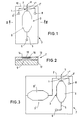
- the outlet channel 1 opens in the sample fluid channel 2 at an angle of im essentially 90 ° and crosses this to the Junction point opposite from the sample fluid channel 2 out of these again, so that the Lumens of both channels are connected.
- the Drop generation by means of the micro ejection pump can in particular through two different operating principles be realized. So it is possible that pressure surge required for drop ejection by means of a Temperature jump in a small area in the Micro ejection pump located working fluid the so-called thermal or bubble jet principle realize.
- the micro ejection pump can be optionally also operated by means of a piezoelectric actuator become.
- the micro ejection pump is activated according to the so-called drop-on-demand principle dispensing a mixture of preferably inert Working fluid and the sample fraction to be dispensed.
- the outlet channel is connected to the pressure chamber 9 of the micropump 3 connected.
- the pressure chamber 9 is via an inlet channel 5 working fluid from a (not shown) Supply container supplied with the connection 6 with the inlet channel 5 is connectable.
- the volume of the fluid structure in the Decisive compared to the state of the art reduce.
- a quick change of the sample fluid and thus a high sample throughput are made possible.
- the device according to the invention thus the possibility of fragments such.
- the smallest, sample fractions already present in high resolution can be isolated without backmixing.
- the working fluid together as a rinsing liquid be used.
- the sample fluid channel has two connections 8,8 ', between which the channel is in the substrate 7 extends.
- the runs across the sample fluid channel 2 Outlet channel 1, the first section 1 'and one second section 1 ".
- the first section 1 ' extends from the pressure chamber 9 of the micropump 3 to the sample fluid channel 2.
- the second section 1 " runs in extension of the first section 1 'of Sample fluid channel 2 to the edge 10 of the substrate 7, where the outlet opening 11 is located.
- the first Section 1 'of the outlet channel 1 is also called the working fluid channel referred to, because through this section the working fluid located in the pressure chamber 9 flows.
- Through the second channel section 1 " so-called discharge channel, working fluid with velvet the fraction to be ejected of the sample fluid channel 2 flowing sample fluid.
- the working fluid arrives via the inlet channel 5 into the pressure chamber 9.
- the dimensioning of the microstructure channels according to the invention allows the pressurization of the Working fluids this not via the inlet channel 5, but escapes through the outlet duct 1, and that at the subsequent relaxation of the working fluid observe that working fluid is out of the reservoir via the inlet channel 5 into the chamber of Micropump 3 arrives and not about the one with the Sample fluid channel 2 connected outlet channel 1 working fluid, optionally mixed with sample liquid, is sucked back into the chamber.
- the length of the sample fluid channel 2 can be made variable and thus enables a suitable Coupling the device according to the invention to existing Separation and analysis systems.
- the width B and the depth T of the sample fluid channel are preferred so that 0.1 mm ⁇ B ⁇ 0.5 mm and 0.04 mm ⁇ T ⁇ 0.08 mm applies.
- the length of the inlet channel 5 is also variable customizable.
- the width B is expediently 0.1 ⁇ B ⁇ 0.3 mm.
- the inlet channel points in particular a depth T for which 0.04 mm ⁇ T ⁇ 0.08 mm applies.
- Fig. 2 is also a section along the line II-II represented by the pumping chamber. It can be seen that the substrate 7 from a glass substrate 12 and a silicon wafer 13 applied thereon. In the Underside of the silicon wafer 13 are depressions etched; is the depression for the Pressure chamber 9 shown. Even in the top of the Silicon wafer 13 has a recess 14 etched into it which is a piezo actuator 15. The silicon wafer and the glass substrate are close together connected. By introducing the two wells 9 and 14 is formed in the silicon wafer 13 Diaphragm 16, which is used to build up pressure in the pressure chamber 9 when the piezo actuator 15 is activated shifts.
- the substrate consists of a wafer of a material used in microelectronics and / or micromechanics (for example Si, SiO 2 , Si 3 N 4 , GaAs) or of plastic.
- the production can by means of the methods known to those skilled in the art, such as B. LIGA or injection molding, with extremely high accuracy and reproducibility.
- the electronics required for evaluating the detection signal and controlling the micro-ejection pump can be monolithically integrated in the wafer in a preferred manner.
- the device according to the invention can also consist of a glass-silicon layer structure, the three-dimensionally microstructured silicon body being atomically connected to a glass cover plate by anodic bonding.
- the transport of the sample stream in the sample fluid channel 2 can with a conventional pump by pressing on the inlet connector 8 or suction at the outlet port 8 'of the sample fluid channel 2 respectively. It is also possible to use the transport another micropump integrated in the substrate 3 'to be carried out.
- This preferred Embodiment is shown in Fig. 3, wherein the above in connection with FIGS. 1 and 2 described features and characteristics also in the 3 are given.
- the detection of the sample fragments to be selected can by means of a sensor element, which is in Direction of the sample stream at a suitable distance or also directly in the area of the intersection of the sample fluid channel 2 with the outlet channel 1 of the micropump 3 located.
- the detection method is fluorescence correlation spectroscopy according to WO-A-94/16313 to be used, which the functional characterization of individual molecules or molecular complexes, viruses or single cells allowed. It can also be based on an optical analysis system the basis of near-field spectroscopy according to WO-A-96/13744 be used.
- the control of the micro ejection pump upon detection of a desired sample fragment can by means of control units, as the expert are known to take place.
- the device according to the invention not only takes place Use in the separation of previously identified Particles.
- it can also be used as an alternative used for conventional dispensing devices become.
- it may be desirable that the working fluid and the sample fluid are identical.
- the device can be used as a single element or as an array structure Part of automated separation systems his. In particular, several can. Sample fluid channels with the associated micro ejection pump be integrated monolithically on a wafer. It can also desirable for certain applications be according to the inventive method separated sample fragments using an in EP-A-0 672 834 described microfluidic diode in a Coupling in the target fluid.
- This micropump 3 ′ has one in the substrate 7 integrated pressure / suction chamber 9 'in the Sample fluid channel 2 is switched. Otherwise the same the embodiment of FIG. 3 after that Fig. 1.
- Micro ejection pump can be especially with the Combine the subject of DE-C-195 44 127, the multi-electrode arrangement for control mentioned there the position and / or the change in position suspended particles of the sample fluid in the sample fluid channel 2 is arranged.
- the Sample fluid channel 2 for microparticle positioning provided with electrode arrangements as in DE-C-196 53 659 and DE-C-196 53 661 are.
Landscapes
- Chemical & Material Sciences (AREA)
- Health & Medical Sciences (AREA)
- Clinical Laboratory Science (AREA)
- Chemical Kinetics & Catalysis (AREA)
- Dispersion Chemistry (AREA)
- Analytical Chemistry (AREA)
- General Health & Medical Sciences (AREA)
- Hematology (AREA)
- Automatic Analysis And Handling Materials Therefor (AREA)
- Reciprocating Pumps (AREA)
- Sampling And Sample Adjustment (AREA)
- Investigating Or Analysing Biological Materials (AREA)
Description
- Fig. 1
- eine Draufsicht auf ein Substrat mit einem Probenfluidkanal und diesen kreuzenden Arbeitsfluid- und Ausstoßkanälen sowie einer druckbeaufschlagbaren Druckkammer, der über einen Zulaufkanal Arbeitsfluid zugeführt wird,
- Fig. 2
- einen Schnitt entlang der Linie II-II der Fig. 1 und
- Fig. 3
- eine Draufsicht auf ein mikromechanisch bearbeitetes Substrat für eine alternative Ausgestaltung einer Ejektionspumpe mit einer integrierten Pumpenkammer für das Arbeitsfluid und einer Pumpenkammer für das Probenfluid.
Claims (8)
- Mikromechanische Ejektionspumpe zum Heraustrennen kleinster Fluidvolumina aus einem strömenden Probenfluid, mitgekennzeichnet durcheinem Substrat (7),einem in dem Substrat (7) ausgebildeten Probenfluidkanal (2) für ein Probenfluid,einen in dem Substrat (7) ausgebildeten Arbeitsfluidkanal (1') für druckbeaufschlagbares Arbeitsfluid,einen Zulaufkanal (5), über den dem Arbeitsfluidkanal (1') Arbeitsfluid zuführbar ist,einen Ausstoßkanal (1") zum Ausstoßen eines Fluidvolumens aus dem Probenfluid, undeine in dem Substrat (7) integrierte und mit dem Arbeitsfluidkanal (1') verbundene erste Pumpe (3) für das Arbeitsfluid, die zwischen dem Arbeitsfluidkanal (1') und dem Zuführkanal (5) angeordnet ist, wobeider Arbeitsfluidkanal (1') quer zur Erstreckung des Probenfluidkanals (2) verlaufend in diesen einmündet,der mit dem Probenfluidkanal (2) verbundene Ausstoßkanal (1") dem Arbeitsfluidkanal (1') gegenüberliegend von dem Probenfluidkanal (2) abzweigt,der Probenfluidkanal (2), der Arbeitsfluidkanal (1') und der Ausstoßkanal (1") miteinander in Fluidverbindung stehen, undder Arbeitsfluidkanal (1'), der Ausstoßkanal (1") und der Probenfluidkanal (2) zumindest im Bereich ihrer Fluidverbindung ihre Querschnittsflächen bestimmenden Abmessungen aufweisen, die im Submillimeterbereich, insbesondere im Bereich zwischen ca. 0,9 und 0,01 mm liegen.
- Mikromechanische Ejektionspumpe nach Anspruch 1, dadurch gekennzeichnet, daß das Verhältnis aus dem Querschnitt des Probenfluidkanals (2) zu dem Querschnitt des Arbeitsfluid- bzw. Ausstoßkanals (1',1") zwischen 0,2 und 0,5, insbesondere zwischen 0,3 und 0,4 und vorzugsweise bei 0,35 liegt.
- Mikromechanische Ejektionspumpe nach Anspruch 1 oder 2, dadurch gekennzeichnet, daß der Arbeitsfluidkanal (1') und der Ausstoßkanal (1") im wesentlichen den gleichen Querschnitt zwischen 0,01 mm2 bis 0,12 mm2 aufweisen.
- Mikromechanische Ejektionspumpe nach einem der Ansprüche 1 bis 3, dadurch gekennzeichnet, daß der Probenfluidkanal (2), der Arbeitsfluidkanal (1') und der Ausstoßkanal (1") im Bereich ihrer Einmündungs- und Abzweigungsbereiche sämtlich geradlinig verlaufen.
- Mikromechanische Ejektionspumpe nach Anspruch 4, dadurch gekennzeichnet, daß sich der Arbeitsfluidkanal (1') und der Ausstoßkanal (1") entlang einer gemeinsamen geradlinigen Längsachse erstrecken, die quer zur Längsachse des Probenfluidkanals (2) verläuft.
- Mikromechanische Ejektionspumpe nach einem der Ansprüche 1 bis 5, dadurch gekennzeichnet, daß die erste Pumpe eine Druckkammer (9) mit einer Membran (16) aufweist, auf die zum Pumpen von Arbeitsfluid durch den Arbeitsfluidkanal (1') ein Piezoaktuator (15) einwirkt.
- Mikromechanische Ejektionspumpe nach einem der Ansprüche 1 bis 6, dadurch gekennzeichnet, daß in das Substrat (7) eine mit dem Probenfluidkanal (2) verbundene zweite Pumpe (3') für das Probenfluid integriert ist.
- Mikromechanische Ejektionspumpe nach Anspruch 7, dadurch gekennzeichnet, daß die zweite Pumpe (3') eine Druckkammer (9') mit einer Membran aufweist, auf die zum Pumpen von Probenfluid durch den Probenfluidkanal (2) ein Piezoaktuator einwirkt.
Applications Claiming Priority (3)
| Application Number | Priority Date | Filing Date | Title |
|---|---|---|---|
| DE19648458 | 1996-11-22 | ||
| DE19648458A DE19648458C1 (de) | 1996-11-22 | 1996-11-22 | Mikromechanische Ejektionspumpe zum Heraustrennen kleinster Fluidvolumina aus einem strömenden Probenfluid |
| PCT/EP1997/006543 WO1998023376A1 (de) | 1996-11-22 | 1997-11-22 | Mikromechanische ejektionspumpe zum heraustrennen kleinster fluidvolumina aus einem strömenden probenfluid |
Publications (2)
| Publication Number | Publication Date |
|---|---|
| EP0939675A1 EP0939675A1 (de) | 1999-09-08 |
| EP0939675B1 true EP0939675B1 (de) | 2001-11-07 |
Family
ID=7812508
Family Applications (1)
| Application Number | Title | Priority Date | Filing Date |
|---|---|---|---|
| EP97951952A Expired - Lifetime EP0939675B1 (de) | 1996-11-22 | 1997-11-22 | Mikromechanische ejektionspumpe zum heraustrennen kleinster fluidvolumina aus einem strömenden probenfluid |
Country Status (5)
| Country | Link |
|---|---|
| US (1) | US6213735B1 (de) |
| EP (1) | EP0939675B1 (de) |
| AT (1) | ATE208233T1 (de) |
| DE (2) | DE19648458C1 (de) |
| WO (1) | WO1998023376A1 (de) |
Families Citing this family (23)
| Publication number | Priority date | Publication date | Assignee | Title |
|---|---|---|---|---|
| GB9800933D0 (en) * | 1998-01-17 | 1998-03-11 | Central Research Lab Ltd | A dispenser |
| DE10001116C2 (de) * | 2000-01-13 | 2002-11-28 | Meinhard Knoll | Vorrichtung und Verfahren zur optischen oder elektrochemischen quantitativen Bestimmung chemischer oder biochemischer Substanzen in flüssigen Proben |
| US6579068B2 (en) * | 2000-08-09 | 2003-06-17 | California Institute Of Technology | Method of manufacture of a suspended nitride membrane and a microperistaltic pump using the same |
| CN1269637C (zh) * | 2000-09-18 | 2006-08-16 | 帕尔技术有限责任公司 | 一种压电致动器和使用压电致动器的泵 |
| US7198250B2 (en) * | 2000-09-18 | 2007-04-03 | Par Technologies, Llc | Piezoelectric actuator and pump using same |
| KR100398309B1 (ko) * | 2001-02-20 | 2003-09-19 | 한국과학기술원 | 연속 전기습윤에 의해 유도된 운동하는 액체 방울에 의해구동되는 마이크로펌프 |
| US6932502B2 (en) * | 2002-05-01 | 2005-08-23 | Hewlett-Packard Development Company, L.P. | Mixing apparatus |
| DE10244154A1 (de) * | 2002-09-23 | 2004-04-08 | Prisma Diagnostika Gmbh | Trägerelement für diagnostische Tests |
| US7287965B2 (en) * | 2004-04-02 | 2007-10-30 | Adaptiv Energy Llc | Piezoelectric devices and methods and circuits for driving same |
| US7312554B2 (en) | 2004-04-02 | 2007-12-25 | Adaptivenergy, Llc | Piezoelectric devices and methods and circuits for driving same |
| US20050225201A1 (en) * | 2004-04-02 | 2005-10-13 | Par Technologies, Llc | Piezoelectric devices and methods and circuits for driving same |
| US7290993B2 (en) * | 2004-04-02 | 2007-11-06 | Adaptivenergy Llc | Piezoelectric devices and methods and circuits for driving same |
| US20060147329A1 (en) * | 2004-12-30 | 2006-07-06 | Tanner Edward T | Active valve and active valving for pump |
| US7258533B2 (en) * | 2004-12-30 | 2007-08-21 | Adaptivenergy, Llc | Method and apparatus for scavenging energy during pump operation |
| JP2008537461A (ja) * | 2005-04-13 | 2008-09-11 | アダプティブエナジー・リミテッド・ライアビリティー・カンパニー | フレキシブル膜上に導体を備える圧電ダイヤフラムアセンブリ |
| US20060232166A1 (en) * | 2005-04-13 | 2006-10-19 | Par Technologies Llc | Stacked piezoelectric diaphragm members |
| US20070075286A1 (en) * | 2005-10-04 | 2007-04-05 | Par Technologies, Llc | Piezoelectric valves drive |
| US20070129681A1 (en) * | 2005-11-01 | 2007-06-07 | Par Technologies, Llc | Piezoelectric actuation of piston within dispensing chamber |
| US7345407B2 (en) | 2005-11-18 | 2008-03-18 | Adaptivenergy, Llc. | Human powered piezoelectric power generating device |
| US20080246367A1 (en) * | 2006-12-29 | 2008-10-09 | Adaptivenergy, Llc | Tuned laminated piezoelectric elements and methods of tuning same |
| WO2008103963A1 (en) * | 2007-02-22 | 2008-08-28 | Sterling Investments Lc | Micro fluid transfer system |
| DE102015200530B4 (de) | 2015-01-15 | 2021-03-25 | Gud Geotechnik Und Dynamik Consult Gmbh | Verfahren zur Bewertung von Düsenstrahlsäulen |
| DE102018111822B4 (de) * | 2018-05-16 | 2021-10-07 | Microfluidic Chipshop Gmbh | Fluidisches System zur Aufnahme, Abgabe und Bewegung von Flüssigkeiten, Verfahren zur Verarbeitung von Fluiden in einem fluidischen System |
Family Cites Families (25)
| Publication number | Priority date | Publication date | Assignee | Title |
|---|---|---|---|---|
| US4024544A (en) * | 1975-11-21 | 1977-05-17 | Xerox Corporation | Meniscus dampening drop generator |
| US4344743A (en) * | 1979-12-04 | 1982-08-17 | Bessman Samuel P | Piezoelectric driven diaphragm micro-pump |
| US4614953A (en) * | 1984-04-12 | 1986-09-30 | The Laitram Corporation | Solvent and multiple color ink mixing system in an ink jet |
| EP0356160A3 (de) * | 1988-08-24 | 1991-09-11 | The Board Of Trustees Of The Leland Stanford Junior University | Kapillarvorrichtung |
| US5205819A (en) * | 1989-05-11 | 1993-04-27 | Bespak Plc | Pump apparatus for biomedical use |
| DE4006152A1 (de) * | 1990-02-27 | 1991-08-29 | Fraunhofer Ges Forschung | Mikrominiaturisierte pumpe |
| DE4135655A1 (de) * | 1991-09-11 | 1993-03-18 | Fraunhofer Ges Forschung | Mikrominiaturisierte, elektrostatisch betriebene membranpumpe |
| JP3161635B2 (ja) * | 1991-10-17 | 2001-04-25 | ソニー株式会社 | インクジェットプリントヘッド及びインクジェットプリンタ |
| EP0679251B1 (de) * | 1993-01-18 | 1998-04-08 | Evotec BioSystems GmbH | Verfahren und vorrichtung zur bewertung der fitness von biopolymeren |
| CH689836A5 (fr) * | 1994-01-14 | 1999-12-15 | Westonbridge Int Ltd | Micropompe. |
| DE4405004A1 (de) | 1994-02-17 | 1995-08-24 | Rossendorf Forschzent | Chemischer Mikro-Analysator |
| DE4405026A1 (de) * | 1994-02-17 | 1995-08-24 | Rossendorf Forschzent | Mikro-Fluidmanipulator |
| US5472577A (en) * | 1994-06-30 | 1995-12-05 | Iowa State University Research Foundation | Fluid pumping system based on electrochemically-induced surface tension changes |
| US6001229A (en) * | 1994-08-01 | 1999-12-14 | Lockheed Martin Energy Systems, Inc. | Apparatus and method for performing microfluidic manipulations for chemical analysis |
| DE4438391C2 (de) * | 1994-10-27 | 1997-07-03 | Evotec Biosystems Gmbh | Vorrichtung zur Bestimmung stoffspezifischer Parameter eines oder weniger Moleküle mittels Korrelations-Spektroskopie |
| SE9502251D0 (sv) * | 1995-06-21 | 1995-06-21 | Pharmacia Ab | Flow-through sampling cell and use thereof |
| US5856174A (en) * | 1995-06-29 | 1999-01-05 | Affymetrix, Inc. | Integrated nucleic acid diagnostic device |
| US5705813A (en) * | 1995-11-01 | 1998-01-06 | Hewlett-Packard Company | Integrated planar liquid handling system for maldi-TOF MS |
| US5693016A (en) * | 1995-11-08 | 1997-12-02 | Gumaste; Anand V. | Solid state fluid delivery system |
| DE19544127C1 (de) | 1995-11-27 | 1997-03-20 | Gimsa Jan Dr | Verfahren und Vorrichtung zur Erzeugung von Resonanzerscheinungen in Partikelsuspensionen und ihre Verwendung |
| US6010316A (en) * | 1996-01-16 | 2000-01-04 | The Board Of Trustees Of The Leland Stanford Junior University | Acoustic micropump |
| SE9601719D0 (sv) * | 1996-05-06 | 1996-05-06 | Siemens Elema Ab | Doserare för tillförsel av tillsatsgas eller vätska till andningsgas vid anestesiapparat eller ventilator |
| US6083762A (en) * | 1996-05-31 | 2000-07-04 | Packard Instruments Company | Microvolume liquid handling system |
| US5961298A (en) * | 1996-06-25 | 1999-10-05 | California Institute Of Technology | Traveling wave pump employing electroactive actuators |
| US6116863A (en) * | 1997-05-30 | 2000-09-12 | University Of Cincinnati | Electromagnetically driven microactuated device and method of making the same |
-
1996
- 1996-11-22 DE DE19648458A patent/DE19648458C1/de not_active Expired - Lifetime
-
1997
- 1997-11-22 US US09/308,705 patent/US6213735B1/en not_active Expired - Lifetime
- 1997-11-22 DE DE59705302T patent/DE59705302D1/de not_active Expired - Lifetime
- 1997-11-22 AT AT97951952T patent/ATE208233T1/de not_active IP Right Cessation
- 1997-11-22 WO PCT/EP1997/006543 patent/WO1998023376A1/de not_active Ceased
- 1997-11-22 EP EP97951952A patent/EP0939675B1/de not_active Expired - Lifetime
Also Published As
| Publication number | Publication date |
|---|---|
| DE19648458C1 (de) | 1998-07-09 |
| US6213735B1 (en) | 2001-04-10 |
| WO1998023376A1 (de) | 1998-06-04 |
| ATE208233T1 (de) | 2001-11-15 |
| DE59705302D1 (de) | 2001-12-13 |
| EP0939675A1 (de) | 1999-09-08 |
Similar Documents
| Publication | Publication Date | Title |
|---|---|---|
| DE19648458C1 (de) | Mikromechanische Ejektionspumpe zum Heraustrennen kleinster Fluidvolumina aus einem strömenden Probenfluid | |
| DE60117146T2 (de) | System zur parallelen und selektiven Verteilung von Mikrotröpfchen | |
| DE112011103579B4 (de) | Mehrschichtiger Mikrofluidik-Sondenkopf mit lmmersionskanälen und Herstellung davon | |
| DE60301180T2 (de) | Mikrofluidische Vorrichtung bestehend zumindest teilweise aus elastischem Material | |
| EP0725267B1 (de) | Elektrisch steuerbare Mikro-Pipette | |
| DE69630036T2 (de) | Durchflusszelle für proben und deren verwendung | |
| EP1198294B1 (de) | Mikrofluidischer reaktionsträger mit drei strömungsebenen | |
| DE60300980T2 (de) | Lochmikromischer | |
| EP1289661B1 (de) | Vorrichtung und verfahren zum einspritzen von flüssigkeiten | |
| DE10309583B4 (de) | Mikroanalytisches Element | |
| DE10344700A1 (de) | Mehrkanal-Pipettiervorrichtung | |
| EP1160573A2 (de) | Mikrotiterplatte und gekoppeltes Vielfachpipettiergerät | |
| EP3336519A1 (de) | Vorrichtung und verfahren zum dispensieren von unter verwendung eines akustischen felds ausgerichteten partikeln in frei fliegenden tropfen | |
| JP6962639B2 (ja) | 大スケール表面処理装置を有する垂直マイクロ流体プローブヘッド | |
| DE10010208C2 (de) | Mikrodosiervorrichtung zur definierten Abgabe kleiner in sich geschlossener Flüssigkeitsvolumina | |
| DE10326607A1 (de) | Vorrichtung zum Handhaben von Flüssigkeiten | |
| EP1333926B1 (de) | Vorrichtung und system zur abgabe bzw. aufnahme/abgabe von flüssigkeitsproben | |
| DE112016000223T5 (de) | Mikrofluidik-Sondenkopf zum Verarbeiten einer Sequenz von Flüssigkeitsvolumina, getrennt durch Abstandhalter | |
| EP1351766B1 (de) | Vorrichtung und verfahren zum dosieren kleiner flüssigkeitsmengen | |
| EP0672834B1 (de) | Mikro-Fluidmanipulator | |
| EP0993869B1 (de) | Pipettiervorrichtung | |
| DE102005000835B3 (de) | Verfahren und Vorrichtung zur Dosierung kleiner Flüssigkeitsmengen | |
| DE112013003437T5 (de) | Analysesystem und Analyseverfahren | |
| EP1142642B1 (de) | Mikropumpe zur Abgabe von kleinen Flüssigkeitstropfen | |
| EP2006022B1 (de) | Probenbehandlungsanordnung für eine Flüssigkeitsdosiervorrichtung |
Legal Events
| Date | Code | Title | Description |
|---|---|---|---|
| PUAI | Public reference made under article 153(3) epc to a published international application that has entered the european phase |
Free format text: ORIGINAL CODE: 0009012 |
|
| 17P | Request for examination filed |
Effective date: 19990515 |
|
| AK | Designated contracting states |
Kind code of ref document: A1 Designated state(s): AT BE CH DE DK ES FI FR GB GR IE IT LI LU MC NL PT SE |
|
| 17Q | First examination report despatched |
Effective date: 19991122 |
|
| GRAG | Despatch of communication of intention to grant |
Free format text: ORIGINAL CODE: EPIDOS AGRA |
|
| GRAG | Despatch of communication of intention to grant |
Free format text: ORIGINAL CODE: EPIDOS AGRA |
|
| GRAH | Despatch of communication of intention to grant a patent |
Free format text: ORIGINAL CODE: EPIDOS IGRA |
|
| GRAH | Despatch of communication of intention to grant a patent |
Free format text: ORIGINAL CODE: EPIDOS IGRA |
|
| GRAA | (expected) grant |
Free format text: ORIGINAL CODE: 0009210 |
|
| AK | Designated contracting states |
Kind code of ref document: B1 Designated state(s): AT BE CH DE DK ES FI FR GB GR IE IT LI LU MC NL PT SE |
|
| PG25 | Lapsed in a contracting state [announced via postgrant information from national office to epo] |
Ref country code: NL Free format text: LAPSE BECAUSE OF FAILURE TO SUBMIT A TRANSLATION OF THE DESCRIPTION OR TO PAY THE FEE WITHIN THE PRESCRIBED TIME-LIMIT Effective date: 20011107 Ref country code: IT Free format text: LAPSE BECAUSE OF FAILURE TO SUBMIT A TRANSLATION OF THE DESCRIPTION OR TO PAY THE FEE WITHIN THE PRESCRIBED TIME-LIMIT;WARNING: LAPSES OF ITALIAN PATENTS WITH EFFECTIVE DATE BEFORE 2007 MAY HAVE OCCURRED AT ANY TIME BEFORE 2007. THE CORRECT EFFECTIVE DATE MAY BE DIFFERENT FROM THE ONE RECORDED. Effective date: 20011107 Ref country code: IE Free format text: LAPSE BECAUSE OF FAILURE TO SUBMIT A TRANSLATION OF THE DESCRIPTION OR TO PAY THE FEE WITHIN THE PRESCRIBED TIME-LIMIT Effective date: 20011107 Ref country code: GR Free format text: LAPSE BECAUSE OF FAILURE TO SUBMIT A TRANSLATION OF THE DESCRIPTION OR TO PAY THE FEE WITHIN THE PRESCRIBED TIME-LIMIT Effective date: 20011107 Ref country code: FR Free format text: LAPSE BECAUSE OF FAILURE TO SUBMIT A TRANSLATION OF THE DESCRIPTION OR TO PAY THE FEE WITHIN THE PRESCRIBED TIME-LIMIT Effective date: 20011107 Ref country code: FI Free format text: LAPSE BECAUSE OF FAILURE TO SUBMIT A TRANSLATION OF THE DESCRIPTION OR TO PAY THE FEE WITHIN THE PRESCRIBED TIME-LIMIT Effective date: 20011107 |
|
| REF | Corresponds to: |
Ref document number: 208233 Country of ref document: AT Date of ref document: 20011115 Kind code of ref document: T |
|
| REG | Reference to a national code |
Ref country code: CH Ref legal event code: EP |
|
| PG25 | Lapsed in a contracting state [announced via postgrant information from national office to epo] |
Ref country code: MC Free format text: LAPSE BECAUSE OF NON-PAYMENT OF DUE FEES Effective date: 20011122 Ref country code: LU Free format text: LAPSE BECAUSE OF NON-PAYMENT OF DUE FEES Effective date: 20011122 Ref country code: AT Free format text: LAPSE BECAUSE OF NON-PAYMENT OF DUE FEES Effective date: 20011122 |
|
| PG25 | Lapsed in a contracting state [announced via postgrant information from national office to epo] |
Ref country code: BE Free format text: LAPSE BECAUSE OF NON-PAYMENT OF DUE FEES Effective date: 20011130 |
|
| REG | Reference to a national code |
Ref country code: IE Ref legal event code: FG4D Free format text: GERMAN |
|
| REF | Corresponds to: |
Ref document number: 59705302 Country of ref document: DE Date of ref document: 20011213 |
|
| REG | Reference to a national code |
Ref country code: GB Ref legal event code: IF02 |
|
| RAP2 | Party data changed (patent owner data changed or rights of a patent transferred) |
Owner name: EVOTEC OAI AG |
|
| REG | Reference to a national code |
Ref country code: CH Ref legal event code: NV Representative=s name: SCHMAUDER & PARTNER AG PATENTANWALTSBUERO |
|
| PG25 | Lapsed in a contracting state [announced via postgrant information from national office to epo] |
Ref country code: SE Free format text: LAPSE BECAUSE OF FAILURE TO SUBMIT A TRANSLATION OF THE DESCRIPTION OR TO PAY THE FEE WITHIN THE PRESCRIBED TIME-LIMIT Effective date: 20020207 Ref country code: PT Free format text: LAPSE BECAUSE OF FAILURE TO SUBMIT A TRANSLATION OF THE DESCRIPTION OR TO PAY THE FEE WITHIN THE PRESCRIBED TIME-LIMIT Effective date: 20020207 Ref country code: DK Free format text: LAPSE BECAUSE OF FAILURE TO SUBMIT A TRANSLATION OF THE DESCRIPTION OR TO PAY THE FEE WITHIN THE PRESCRIBED TIME-LIMIT Effective date: 20020207 |
|
| NLT2 | Nl: modifications (of names), taken from the european patent patent bulletin |
Owner name: EVOTEC OAI AG |
|
| GBT | Gb: translation of ep patent filed (gb section 77(6)(a)/1977) |
Effective date: 20020207 |
|
| NLV1 | Nl: lapsed or annulled due to failure to fulfill the requirements of art. 29p and 29m of the patents act | ||
| PG25 | Lapsed in a contracting state [announced via postgrant information from national office to epo] |
Ref country code: ES Free format text: LAPSE BECAUSE OF FAILURE TO SUBMIT A TRANSLATION OF THE DESCRIPTION OR TO PAY THE FEE WITHIN THE PRESCRIBED TIME-LIMIT Effective date: 20020530 |
|
| BERE | Be: lapsed |
Owner name: EVOTEC BIOSYSTEMS A.G. Effective date: 20011130 |
|
| REG | Reference to a national code |
Ref country code: IE Ref legal event code: FD4D |
|
| EN | Fr: translation not filed | ||
| PLBE | No opposition filed within time limit |
Free format text: ORIGINAL CODE: 0009261 |
|
| STAA | Information on the status of an ep patent application or granted ep patent |
Free format text: STATUS: NO OPPOSITION FILED WITHIN TIME LIMIT |
|
| 26N | No opposition filed | ||
| REG | Reference to a national code |
Ref country code: CH Ref legal event code: PCAR Free format text: SCHMAUDER & PARTNER AG PATENT- UND MARKENANWAELTE VSP;ZWAENGIWEG 7;8038 ZUERICH (CH) |
|
| PGFP | Annual fee paid to national office [announced via postgrant information from national office to epo] |
Ref country code: GB Payment date: 20161124 Year of fee payment: 20 Ref country code: DE Payment date: 20161129 Year of fee payment: 20 Ref country code: CH Payment date: 20161124 Year of fee payment: 20 |
|
| REG | Reference to a national code |
Ref country code: DE Ref legal event code: R071 Ref document number: 59705302 Country of ref document: DE |
|
| REG | Reference to a national code |
Ref country code: CH Ref legal event code: PL |
|
| REG | Reference to a national code |
Ref country code: GB Ref legal event code: PE20 Expiry date: 20171121 |
|
| PG25 | Lapsed in a contracting state [announced via postgrant information from national office to epo] |
Ref country code: GB Free format text: LAPSE BECAUSE OF EXPIRATION OF PROTECTION Effective date: 20171121 |