EP0937927A2 - Diverter valve - Google Patents
Diverter valve Download PDFInfo
- Publication number
- EP0937927A2 EP0937927A2 EP99102273A EP99102273A EP0937927A2 EP 0937927 A2 EP0937927 A2 EP 0937927A2 EP 99102273 A EP99102273 A EP 99102273A EP 99102273 A EP99102273 A EP 99102273A EP 0937927 A2 EP0937927 A2 EP 0937927A2
- Authority
- EP
- European Patent Office
- Prior art keywords
- hollow piston
- needle
- spindle
- valve
- relief opening
- Prior art date
- Legal status (The legal status is an assumption and is not a legal conclusion. Google has not performed a legal analysis and makes no representation as to the accuracy of the status listed.)
- Granted
Links
Images

Classifications
-
- E—FIXED CONSTRUCTIONS
- E03—WATER SUPPLY; SEWERAGE
- E03C—DOMESTIC PLUMBING INSTALLATIONS FOR FRESH WATER OR WASTE WATER; SINKS
- E03C1/00—Domestic plumbing installations for fresh water or waste water; Sinks
- E03C1/02—Plumbing installations for fresh water
- E03C1/04—Water-basin installations specially adapted to wash-basins or baths
-
- F—MECHANICAL ENGINEERING; LIGHTING; HEATING; WEAPONS; BLASTING
- F16—ENGINEERING ELEMENTS AND UNITS; GENERAL MEASURES FOR PRODUCING AND MAINTAINING EFFECTIVE FUNCTIONING OF MACHINES OR INSTALLATIONS; THERMAL INSULATION IN GENERAL
- F16K—VALVES; TAPS; COCKS; ACTUATING-FLOATS; DEVICES FOR VENTING OR AERATING
- F16K11/00—Multiple-way valves, e.g. mixing valves; Pipe fittings incorporating such valves
- F16K11/02—Multiple-way valves, e.g. mixing valves; Pipe fittings incorporating such valves with all movable sealing faces moving as one unit
- F16K11/04—Multiple-way valves, e.g. mixing valves; Pipe fittings incorporating such valves with all movable sealing faces moving as one unit comprising only lift valves
- F16K11/044—Multiple-way valves, e.g. mixing valves; Pipe fittings incorporating such valves with all movable sealing faces moving as one unit comprising only lift valves with movable valve members positioned between valve seats
- F16K11/0445—Bath/shower selectors
-
- E—FIXED CONSTRUCTIONS
- E03—WATER SUPPLY; SEWERAGE
- E03C—DOMESTIC PLUMBING INSTALLATIONS FOR FRESH WATER OR WASTE WATER; SINKS
- E03C2201/00—Details, devices or methods not otherwise provided for
- E03C2201/30—Diverter valves in faucets or taps
Definitions
- the invention relates to a switching valve for switching from inflowing water to different outlets, e.g. B. bathtub or shower spout, with a as Hollow piston formed closure member is provided which both by hand with an actuator as well as by switching off the water supply automatically adjustable in a preferred outflow position is, for manual operation one of a resilient Device pushed into a neutral rest position, limited displacement with a head part in the hollow piston held, sealed from the water-bearing area lead out spindle is provided, the stroke in Hollow piston corresponds at least to the valve lift, so that the valve closure member without moving the spindle each of the two shut-off positions.
- Such a changeover valve is from the European one Patent EP 0 120 318 B1 known. More recently is increasingly required for hose shower outlets to prevent industrial water from flowing back one or two non-return valves connected in series to provide.
- non-return valves When arranging non-return valves in the area of the shower outlet it can change of the changeover valve during shower operation occur on the tub spout that the closure member abruptly closes the shower water outflow, whereby a vacuum due to the tearing water column between the closure member and the backflow preventer can arise so that the closure member in the shut-off position is blocked and only by relatively large Force can be released from the shut-off position.
- the invention has for its object in the preamble of changeover valve specified so train that blocking in the shut-off position the shower outlet easily by hand with the control device is solvable.
- a relief valve is formed in the bottom of the hollow piston is which is done with a hand Displacement of the spindle from the neutral center or Rest position openable to open the shower outlet while it is in the other positions of the spindle closed to the hollow piston.
- a valve closure member 2 of a changeover valve is arranged in a fitting body 1, the closure member 2 being operable with a spindle 3.
- Connections 10 for the incoming cold and hot water are provided on the valve body 1, a shut-off and mixing valve being arranged in the valve body 1 - not shown in the drawing - from which the mixed water generated is discharged into a mixed water channel 11 .
- the mixed water channel 11 opens radially in the area of the closure member 2 of the changeover valve.
- the closure member 2 is designed as a hollow piston, with a double cone 21 being formed on the outer jacket of the hollow piston 20, which with the aid of the spindle 3 by axially displacing the closure member 2 on the one hand on an annular valve seat 23 for the tub outflow and on the other hand on an annular valve seat 22 for the shower outlet can be brought to the system, so that the mixed water flowing into the mixed water channel 11 can be supplied either to the tub outlet 12 or the shower outlet 13.
- a backflow preventer 5 is arranged downstream behind the valve seat 23, so that a backflow of process water via a hand shower attached to a hose line - not shown in the drawing - is excluded.
- the spindle 3 is axially displaceably mounted in a head piece 220 screwed into the valve body 1.
- An end face of the head piece 220 forms the valve seat 22, which surrounds the tub outlet 12 in a ring shape.
- the tub outlet 12 is formed in the head piece 220 as an annular channel, which emerges downstream into the fitting body 1 via a radial opening in the head piece 220.
- the backflow preventer 5 is arranged coaxially with the head piece 220 in a sleeve 230 which is also screwed into the fitting body 1, the inner end face of which forms the valve seat 23 for the shower outlet 13.
- the spindle 3 is sealed out of the water-carrying area and led out of the head piece 220 and carries an actuating device 30 for the manual actuation of the changeover valve at the outer end area.
- the spindle 3 is axially limited displaceably arranged in the hollow piston 20 with a head part 31 such that, in a neutral central position of the spindle 3, the closure member 2 seals both on the valve seat 23 for the tub outlet and on the valve seat 22 for the shower outlet can concern.
- the spindle 3 is elastically pushed into a neutral central position by two springs 32.
- a return spring 33 acts on the closure member 2 in such a way that the closure member 2 is pressed into a preferred shut-off position, namely against the valve seat 23, when the water inflow is shut off, so that the change-over valve automatically after the showering process has ended, ie the water inflow is shut off Shuts off shower outlet 13 and releases the tub outlet 12.
- a relief valve 4 In the bottom area of the hollow piston 2 there is a relief valve 4, as is the case in particular in FIG. 2 can be seen.
- a closing element of the relief valve 4 is a coaxial on the end face of the Head portion 31 trained needle 40 provided so is dimensioned that in a neutral middle position the spindle 3 has a relief opening 41 from the needle 40 in all axial positions of the closure member 2, So both in the system on valve seat 23 and on Valve seat 22, shut off.
- the needle 40 penetrates here the opening 41.
- a flat 42 is formed, the flat 42 is arranged so that when the closure member 2 rests on the valve seat 23 and the head part 31 continue from the neutral middle position with the help the actuator 30 pulled out by the user is through a relief or overflow channel releases the relief opening 41.
- This enables that when switching from the shower spout on the tub spout between the backflow preventer 5 and the closure member 2 forming negative pressure can be relieved without additional effort.
- the Relief opening 41 with a rubber-elastic lining 45 provided in the bottom of the hollow piston 20th molded, glued or buttoned can.
- the needle 40 can be made in one piece on the head part 31 formed or in a bore in the head part 31st be kept.
- the needle 40 can expediently made of a resilient stainless material become.
- the needle 40 is here essentially with a cylindrical outer surface provided, in the projecting forehead area preferably conical bevel 44.
- in the Bottom of the hollow piston 20 is one of the inside Corresponding, preferably conical countersink 43 formed on which the relief opening 41 connects.
- the needle 40 is here in the Length dimensioned so that the bevel 44 at a extremely pulled out valve stem 3 not completely the depression 43 can be removed. The needle 40 is thus from the depression 43 from the relief position, as shown in Fig. 3, for sure Barrier returned to the relief opening 41.
- Fig. 4 is a modified to Fig. 3 training shown a relief valve.
- the relief opening 41 is arranged in a sleeve 46, by means of thread 460 in the bottom of the hollow piston 20 can be screwed in.
Landscapes
- Engineering & Computer Science (AREA)
- General Engineering & Computer Science (AREA)
- Health & Medical Sciences (AREA)
- Life Sciences & Earth Sciences (AREA)
- Hydrology & Water Resources (AREA)
- Public Health (AREA)
- Water Supply & Treatment (AREA)
- Mechanical Engineering (AREA)
- Multiple-Way Valves (AREA)
- Lubrication Of Internal Combustion Engines (AREA)
- Bathtubs, Showers, And Their Attachments (AREA)
- Magnetically Actuated Valves (AREA)
- Mechanically-Actuated Valves (AREA)
- Seal Device For Vehicle (AREA)
- Valve-Gear Or Valve Arrangements (AREA)
- Valve Device For Special Equipments (AREA)
- Glass Compositions (AREA)
- Check Valves (AREA)
- Sorption Type Refrigeration Machines (AREA)
- Sanitary Device For Flush Toilet (AREA)
- Reciprocating Pumps (AREA)
- Lift Valve (AREA)
- Domestic Plumbing Installations (AREA)
- Sampling And Sample Adjustment (AREA)
Abstract
Description
Die Erfindung betrifft ein Umschaltventil zum Umschalten von zufließendem Wasser zu verschiedenen Ausläufen, z. B. Badewannen- oder Brauseauslauf, wobei ein als Hohlkolben ausgebildetes Verschlußglied vorgesehen ist, welches sowohl von Hand mit einer Betätigungseinrichtung als auch durch ein Abstellen des Wasserzulaufs automatisch in eine bevorzugte Ausflußstellung stellbar ist, wobei zur Handbetätigung ein von einer federnden Einrichtung in eine neutrale Ruheposition gedrängte, mit einem Kopfteil im Hohlkolben begrenzt verschiebbar gehaltene, aus dem wasserführenden Bereich gedichtet herausgeführte Spindel vorgesehen ist, deren Hub im Hohlkolben wenigstens dem Ventilhub entspricht, so daß das Ventilverschlußglied ohne Bewegung der Spindel jede der beiden Absperrstellungen einnehmen kann.The invention relates to a switching valve for switching from inflowing water to different outlets, e.g. B. bathtub or shower spout, with a as Hollow piston formed closure member is provided which both by hand with an actuator as well as by switching off the water supply automatically adjustable in a preferred outflow position is, for manual operation one of a resilient Device pushed into a neutral rest position, limited displacement with a head part in the hollow piston held, sealed from the water-bearing area lead out spindle is provided, the stroke in Hollow piston corresponds at least to the valve lift, so that the valve closure member without moving the spindle each of the two shut-off positions.
Ein derartiges Umschaltventil ist aus der europäischen Patentschrift EP 0 120 318 B1 bekannt. In neuerer Zeit wird zunehmend gefordert, bei Schlauchbrauseabgängen zur Sicherung gegen ein Rückfließen von Brauchwasser ein oder auch zwei in Reihe geschaltete Rückflußverhinderer vorzusehen. Bei der Anordnung von Rückflußverhinderern im Bereich des Brauseausflusses kann es beim Umstellen des Umschaltventils während des Brausebetriebs auf den Wannenauslauf auftreten, daß das Verschlußglied den Brausewasserausfluß schlagartig abschließt, wodurch ein Unterdruck durch die abreißende Wassersäule zwischen dem Verschlußglied und dem Rückflußverhinderer entstehen kann, so daß das Verschlußglied in der Absperrstellung blockiert ist und nur durch relativ großen Kraftaufwand aus der Absperrstellung lösbar ist.Such a changeover valve is from the European one Patent EP 0 120 318 B1 known. More recently is increasingly required for hose shower outlets to prevent industrial water from flowing back one or two non-return valves connected in series to provide. When arranging non-return valves in the area of the shower outlet it can change of the changeover valve during shower operation occur on the tub spout that the closure member abruptly closes the shower water outflow, whereby a vacuum due to the tearing water column between the closure member and the backflow preventer can arise so that the closure member in the shut-off position is blocked and only by relatively large Force can be released from the shut-off position.
Der Erfindung liegt die Aufgabe zugrunde, das im Oberbegriff des Anspruchs 1 angegebene Umschaltventil so auszubilden, daß ein Blockieren in der Absperrstellung des Brauseausflusses leicht von Hand mit der Betätigungseinrichtung lösbar ist.The invention has for its object in the preamble of changeover valve specified so train that blocking in the shut-off position the shower outlet easily by hand with the control device is solvable.
Diese Aufgabe wird erfindungsgemäß dadurch gelöst, daß im Boden des Hohlkolbens ein Entlastungsventil ausgebildet ist, welches mit einer von Hand vorgenommenen Verschiebung der Spindel aus der neutralen Mittel- oder Ruheposition zur Öffnung des Brauseausflusses öffenbar ist, während es in den anderen Stellungen der Spindel zum Hohlkolben geschlossen ist.This object is achieved in that A relief valve is formed in the bottom of the hollow piston is which is done with a hand Displacement of the spindle from the neutral center or Rest position openable to open the shower outlet while it is in the other positions of the spindle closed to the hollow piston.
Weitere Ausgestaltungen der Erfindung sind in den Ansprüchen
2 bis 6 angegeben.Further embodiments of the invention are in the
Ein Ausführungsbeispiel der Erfindung ist in der Zeichnung dargestellt und wird im folgenden näher beschrieben. Es zeigt
- Fig. 1
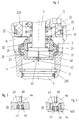
- eine Wassermischbatterie mit einem Umschaltventil für einen Wannenausfluß und einen Brauseausfluß, wobei der Armaturenkörper mit dem Umschaltventil und einem Entlastungsventil im Längsschnitt dargestellt ist;
- Fig. 2
- einen Teil des in Fig. 1 gezeigten Umschaltventils in vergrößerter Darstellung;
- Fig.3
- ein anderes Ausführungsbeispiel eines Entlastungsventils in vergrößerter Darstellung;
- Fig. 4
- ein weiteres Ausführungsbeispiel eines Entlastungsventils in vergrößerter Darstellung.
- Fig. 1
- a water mixer tap with a switching valve for a bath spout and a shower spout, the fitting body with the switching valve and a relief valve being shown in longitudinal section;
- Fig. 2
- a part of the switching valve shown in Figure 1 in an enlarged view.
- Fig. 3
- another embodiment of a relief valve in an enlarged view;
- Fig. 4
- another embodiment of a relief valve in an enlarged view.
Bei der in Fig. 1 dargestellten Wassermischbatterie ist
in einem Armaturenkörper 1 ein Ventilverschlußglied 2
eines Umschaltventils angeordnet, wobei das Verschlußglied
2 mit einer Spindel 3 betätigbar ist. An dem Armaturenkörper
1 sind Anschlüsse 10 für das zufließende
Kalt- und Warmwasser vorgesehen, wobei in dem Armaturenkörper
1 - in der Zeichnung nicht dargestellt - in
bekannter Weise ein Absperr- und Mischventil angeordnet
ist, von dem das erzeugte Mischwasser in einen Mischwasserkanal
11 abgegeben wird. Der Mischwasserkanal 11
mündet radial im Bereich des Verschlußglieds 2 des Umschaltventils.
Das Verschlußglied 2 ist als Hohlkolben
ausgebildet, wobei am Außenmantel des Hohlkolbens 20
ein Doppelkegel 21 ausgebildet ist, der mit Hilfe der
Spindel 3 durch eine axiale Verschiebung des Verschlußglieds
2 einerseits an einem ringförmigen Ventilsitz 23
für den Wannenausfluß und andererseits an einen ringförmigen
Ventilsitz 22 für den Brauseausfluß zur Anlage
bringbar ist, so daß das im Mischwasserkanal 11 zufließende
Mischwasser wahlweise den Wannenausfluß 12 oder
den Brauseausfluß 13 zuführbar ist. In dem Brauseausfluß
13 ist stromabwärts hinter dem Ventilsitz 23 ein
Rückflußverhinderer 5 angeordnet, so daß ein Rückfließen
von Brauchwasser über eine an einer Schlauchleitung
befestigten Handbrause - in der Zeichnung nicht dargestellt
- ausgeschlossen wird. Die Spindel 3 ist dabei
axial verschieblich in einem in dem Armaturenkörper 1
eingeschraubten Kopfstück 220 gelagert. Eine Stirnseite
des Kopfstücks 220 bildet den Ventilsitz 22, der den
Wannenausfluß 12 ringförmig umschließt. Der Wannenausfluß
12 ist im Kopfstück 220 als Ringkanal ausgebildet,
der stromabwärts über eine Radialöffnung im Kopfstück
220 in den Armaturenkörper 1 austritt. Der Rückflußverhinderer
5 ist koaxial zum Kopfstück 220 in einer ebenfalls
im Armaturenkörper 1 eingeschraubten Hülse 230
angeordnet, wobei deren innere Stirnseite den Ventilsitz
23 für den Brauseausfluß 13 bildet. Die Spindel 3
ist aus dem wasserführenden Bereich gedichtet aus dem
Kopfstück 220 herausgeführt und trägt am äußeren Endbereich
eine Betätigungseinrichtung 30 für die Handbetätigung
des Umschaltventils.
Am inneren Endbereich ist die Spindel 3 mit einem Kopfteil
31 axial begrenzt verschieblich in dem Hohlkolben
20 derart angeordnet, daß in einer neutralen Mittelstellung
der Spindel 3 das Verschlußglied 2 sowohl an
dem Ventilsitz 23 für den Wannenausfluß als auch an dem
Ventilsitz 22 für den Brauseausfluß dichtend anliegen
kann. Die Spindel 3 wird hierbei von zwei Federn 32
elastisch in eine neutrale Mittelstellung gedrängt. Außerdem
wirkt auf das Verschlußglied 2 eine Rückstellfeder
33 derart ein, daß das Verschlußglied 2 bei abgestelltem
Wasserzufluß in eine bevorzugte Absperrstellung,
nämlich gegen den Ventilsitz 23, gedrückt wird,
so daß das Umschaltventil nach Beendigung eines Brausevorgangs,
d. h. der Wasserzufluß wird abgesperrt,
selbsttätig den Brauseausfluß 13 absperrt und den Wannenausfluß
12 freigibt.In the water mixer tap shown in Fig. 1, a
At the inner end region, the
Im Bodenbereich des Hohlkolbens 2 ist ein Entlastungsventil
4 ausgebildet, wie es insbesondere aus Fig. 2 zu
entnehmen ist. Als Verschlußglied des Entlastungsventils
4 ist hierbei eine koaxial an der Stirnfläche des
Kopfteils 31 ausgebildete Nadel 40 vorgesehen, die so
dimensioniert ist, daß in einer neutralen Mittelposition
der Spindel 3 eine Entlastungsöffnung 41 von der Nadel
40 in allen Axialpositionen des Verschlußglieds 2,
also sowohl in der Anlage am Ventilsitz 23 als auch am
Ventilsitz 22, absperrt. Die Nadel 40 durchdringt hierbei
die Öffnung 41. Am vorderen Bereich der Nadel 40
ist eine Abflachung 42 ausgebildet, wobei die Abflachung
42 so angeordnet ist, daß sie, wenn das Verschlußglied
2 am Ventilsitz 23 anliegt und das Kopfteil
31 weiter aus der neutralen Mittelposition mit Hilfe
der Betätigungseinrichtung 30 vom Benutzer herausgezogen
wird, einen Entlastungs- bzw. Überströmkanal durch
die Entlastungsöffnung 41 freigibt. Hiermit wird es ermöglicht,
daß bei einer Umschaltung vom Brauseauslauf
auf den Wannenauslauf sich zwischen dem Rückflußverhinderer
5 und dem Verschlußglied 2 bildender Unterdruck
ohne zusätzliche Kraftaufwendung entlastet werden kann.
Zur guten Abdichtung zur Wandung der Nadel 40 ist die
Entlastungsöffnung 41 mit einer gummielastischen Auskleidung
45 versehen, die im Boden des Hohlkolbens 20
angespritzt, angeklebt oder eingeknöpft angeordnet sein
kann. Die Nadel 40 kann einstückig an dem Kopfteil 31
ausgebildet oder auch in einer Bohrung im Kopfteil 31
gehalten sein. Die Nadel 40 kann hierbei zweckmäßig aus
einem federelastischen nichtrostenden Werkstoff hergestellt
werden.In the bottom area of the
In Fig. 3 ist ein anderes Ausführungsbeispiel eines
Entlastungsventils dargestellt. Die Nadel 40 ist hierbei
im wesentlichen mit einer zylindrischen Mantelfläche
versehen, wobei im vorstehenden Stirnbereich eine
vorzugsweise kegelförmige Schrägung 44 ausgebildet. Im
Boden des Hohlkolbens 20 ist an der Innenseite eine der
Schrägung entsprechende, vorzugsweise kegelförmige Aussenkung
43 ausgebildet, an der sich die Entlastungsöffnung
41 anschließt. Die Nadel 40 ist hierbei in der
Länge so dimensioniert, daß die Schrägung 44 bei einer
extrem herausgezogenen Ventilspindel 3 nicht völlig aus
der Aussenkung 43 entfernt werden kann. Die Nadel 40
wird somit von der Aussenkung 43 aus der Entlastungsposition,
wie es in Fig. 3 dargestellt ist, sicher zur
Absperrung in die Entlastungsöffnung 41 zurückgeführt.3 is another embodiment of a
Relief valve shown. The
In Fig. 4 ist eine zur Fig. 3 abgewandelte Ausbildung
eines Entlastungsventils dargestellt. Die Entlastungsöffnung
41 ist hierbei in einer Hülse 46 angeordnet,
die mittels Gewinde 460 in den Boden des Hohlkolbens 20
einschraubbar ist.In Fig. 4 is a modified to Fig. 3 training
shown a relief valve. The
Claims (6)
Applications Claiming Priority (2)
| Application Number | Priority Date | Filing Date | Title |
|---|---|---|---|
| DE19807201A DE19807201A1 (en) | 1998-02-20 | 1998-02-20 | Diverter valve |
| DE19807201 | 1998-02-20 |
Publications (3)
| Publication Number | Publication Date |
|---|---|
| EP0937927A2 true EP0937927A2 (en) | 1999-08-25 |
| EP0937927A3 EP0937927A3 (en) | 2001-02-14 |
| EP0937927B1 EP0937927B1 (en) | 2003-08-20 |
Family
ID=7858431
Family Applications (1)
| Application Number | Title | Priority Date | Filing Date |
|---|---|---|---|
| EP99102273A Expired - Lifetime EP0937927B1 (en) | 1998-02-20 | 1999-02-05 | Diverter valve |
Country Status (6)
| Country | Link |
|---|---|
| EP (1) | EP0937927B1 (en) |
| AT (1) | ATE247790T1 (en) |
| DE (2) | DE19807201A1 (en) |
| DK (1) | DK0937927T3 (en) |
| ES (2) | ES2205610T3 (en) |
| PT (1) | PT937927E (en) |
Cited By (4)
| Publication number | Priority date | Publication date | Assignee | Title |
|---|---|---|---|---|
| WO2007048525A1 (en) * | 2005-10-27 | 2007-05-03 | Hansa Metallwerke Ag | Sanitary reversing valve |
| WO2011160737A1 (en) * | 2010-06-24 | 2011-12-29 | Neoperl Gmbh | Changeover valve |
| WO2015043702A1 (en) * | 2013-09-27 | 2015-04-02 | Grohe Ag | Switchover valve for sanitary fittings |
| EP3848519A1 (en) * | 2020-01-08 | 2021-07-14 | Duravit Aktiengesellschaft | Sanitary device comprising a urinal and a suction siphon to be attached or connected to the urinal and a flushing nozzle |
Citations (1)
| Publication number | Priority date | Publication date | Assignee | Title |
|---|---|---|---|---|
| EP0120318B1 (en) | 1983-02-28 | 1986-11-20 | FRIEDRICH GROHE ARMATURENFABRIK GmbH & CO | Diverter valve |
Family Cites Families (3)
| Publication number | Priority date | Publication date | Assignee | Title |
|---|---|---|---|---|
| DE2004918A1 (en) * | 1970-02-04 | 1971-08-19 | Bopp & Reuther Gmbh | Multi-way valve |
| DE2739196C2 (en) * | 1977-08-31 | 1982-07-22 | Friedrich Grohe Armaturenfabrik Gmbh & Co, 5870 Hemer | Changeover valve |
| DE3043482A1 (en) * | 1980-11-18 | 1982-06-03 | Friedrich Grohe Armaturenfabrik Gmbh & Co, 5870 Hemer | Changeover tap for shower or bathtub - has leaf spring to bias control knob to centre and change valve to preferred setting when switched off |
-
1998
- 1998-02-20 DE DE19807201A patent/DE19807201A1/en not_active Withdrawn
-
1999
- 1999-02-05 ES ES99102273T patent/ES2205610T3/en not_active Expired - Lifetime
- 1999-02-05 PT PT99102273T patent/PT937927E/en unknown
- 1999-02-05 DK DK99102273T patent/DK0937927T3/en active
- 1999-02-05 EP EP99102273A patent/EP0937927B1/en not_active Expired - Lifetime
- 1999-02-05 AT AT99102273T patent/ATE247790T1/en not_active IP Right Cessation
- 1999-02-05 DE DE59906622T patent/DE59906622D1/en not_active Expired - Fee Related
- 1999-02-19 ES ES009900453U patent/ES1042429Y/en not_active Expired - Fee Related
Patent Citations (1)
| Publication number | Priority date | Publication date | Assignee | Title |
|---|---|---|---|---|
| EP0120318B1 (en) | 1983-02-28 | 1986-11-20 | FRIEDRICH GROHE ARMATURENFABRIK GmbH & CO | Diverter valve |
Cited By (4)
| Publication number | Priority date | Publication date | Assignee | Title |
|---|---|---|---|---|
| WO2007048525A1 (en) * | 2005-10-27 | 2007-05-03 | Hansa Metallwerke Ag | Sanitary reversing valve |
| WO2011160737A1 (en) * | 2010-06-24 | 2011-12-29 | Neoperl Gmbh | Changeover valve |
| WO2015043702A1 (en) * | 2013-09-27 | 2015-04-02 | Grohe Ag | Switchover valve for sanitary fittings |
| EP3848519A1 (en) * | 2020-01-08 | 2021-07-14 | Duravit Aktiengesellschaft | Sanitary device comprising a urinal and a suction siphon to be attached or connected to the urinal and a flushing nozzle |
Also Published As
| Publication number | Publication date |
|---|---|
| ES2205610T3 (en) | 2004-05-01 |
| ES1042429Y (en) | 2000-02-01 |
| ES1042429U (en) | 1999-09-01 |
| EP0937927B1 (en) | 2003-08-20 |
| DK0937927T3 (en) | 2003-12-08 |
| DE19807201A1 (en) | 1999-08-26 |
| ATE247790T1 (en) | 2003-09-15 |
| DE59906622D1 (en) | 2003-09-25 |
| EP0937927A3 (en) | 2001-02-14 |
| PT937927E (en) | 2003-11-28 |
Similar Documents
| Publication | Publication Date | Title |
|---|---|---|
| EP0432553B1 (en) | Sanitary fixture | |
| DE69408058T2 (en) | Diverter valve cartridge | |
| DE102005003404B3 (en) | Sanitary outlet unit | |
| DE3637470C2 (en) | Spout for sanitary fittings | |
| EP1707692B1 (en) | Faucet with telescopic spout | |
| EP3189257B1 (en) | Shut-off valve and use of such a shut-off valve | |
| DE2524630A1 (en) | DIVERTING VALVE, IN PARTICULAR FOR SANITARY CONNECTIONS | |
| DE10133041A1 (en) | Mixer tap is fitted with valve cartridge which fits into housing mounted under plaster connecting hot and cold water feeds with bath outlet and shower outlet | |
| WO2011160737A1 (en) | Changeover valve | |
| EP0937927B1 (en) | Diverter valve | |
| DE10239177A1 (en) | Mixer tap has parallel valves for hot and cold water adjusted by rotating rings mounted on tap casing which cooperate with cogwheels on valves | |
| EP0441151A1 (en) | Watertap with backflow preventer | |
| EP1061299A2 (en) | Diverter valve | |
| DE19542748B4 (en) | switching valve | |
| DE3426480C2 (en) | ||
| DE3908009C2 (en) | Sanitary valve | |
| DE4138938A1 (en) | Tap fitment with mixer valve for wash basins - has separate pipe holder fixed at distance at top end of fixing socket, holder attached to water pipes and containing guide channels and fixers for mixer valve | |
| DE2907565C2 (en) | Combined self-closing and mixing valve | |
| EP0942210B1 (en) | Single-hole mixer | |
| DE19649004A1 (en) | Shower unit with hand-held shower | |
| EP1367184A1 (en) | Mixing faucet | |
| DE2616898B2 (en) | Control device for mixing valves | |
| DE2252395A1 (en) | SWITCH FOR A TUB-SHOWER SYSTEM | |
| DE3301181A1 (en) | Single-lever mixing valve | |
| EP0325099A1 (en) | Diverter valve for sanitary fittings |
Legal Events
| Date | Code | Title | Description |
|---|---|---|---|
| PUAI | Public reference made under article 153(3) epc to a published international application that has entered the european phase |
Free format text: ORIGINAL CODE: 0009012 |
|
| AK | Designated contracting states |
Kind code of ref document: A2 Designated state(s): AT BE CH DE DK ES FI FR GB IT LI NL PT SE |
|
| AX | Request for extension of the european patent |
Free format text: AL;LT;LV;MK;RO;SI |
|
| RAP1 | Party data changed (applicant data changed or rights of an application transferred) |
Owner name: FRIEDRICH GROHE AG & CO. KG |
|
| PUAL | Search report despatched |
Free format text: ORIGINAL CODE: 0009013 |
|
| AK | Designated contracting states |
Kind code of ref document: A3 Designated state(s): AT BE CH CY DE DK ES FI FR GB GR IE IT LI LU MC NL PT SE |
|
| AX | Request for extension of the european patent |
Free format text: AL;LT;LV;MK;RO;SI |
|
| 17P | Request for examination filed |
Effective date: 20010630 |
|
| AKX | Designation fees paid |
Free format text: AT BE CH DE DK ES FI FR GB IT LI NL PT SE |
|
| GRAH | Despatch of communication of intention to grant a patent |
Free format text: ORIGINAL CODE: EPIDOS IGRA |
|
| GRAH | Despatch of communication of intention to grant a patent |
Free format text: ORIGINAL CODE: EPIDOS IGRA |
|
| GRAA | (expected) grant |
Free format text: ORIGINAL CODE: 0009210 |
|
| AK | Designated contracting states |
Designated state(s): AT BE CH DE DK ES FI FR GB IT LI NL PT SE |
|
| REG | Reference to a national code |
Ref country code: GB Ref legal event code: FG4D Free format text: NOT ENGLISH |
|
| REG | Reference to a national code |
Ref country code: CH Ref legal event code: NV Representative=s name: BOVARD AG PATENTANWAELTE Ref country code: CH Ref legal event code: EP |
|
| REF | Corresponds to: |
Ref document number: 59906622 Country of ref document: DE Date of ref document: 20030925 Kind code of ref document: P |
|
| RAP2 | Party data changed (patent owner data changed or rights of a patent transferred) |
Owner name: GROHE WATER TECHNOLOGY AG & CO. KG |
|
| REG | Reference to a national code |
Ref country code: SE Ref legal event code: TRGR |
|
| REG | Reference to a national code |
Ref country code: DK Ref legal event code: T3 |
|
| REG | Reference to a national code |
Ref country code: PT Ref legal event code: PD4A Free format text: GROHE WATER TECHNOLOGY AG & CO. KG DE Effective date: 20031030 |
|
| GBT | Gb: translation of ep patent filed (gb section 77(6)(a)/1977) |
Effective date: 20031211 |
|
| PGFP | Annual fee paid to national office [announced via postgrant information from national office to epo] |
Ref country code: PT Payment date: 20040119 Year of fee payment: 6 |
|
| PGFP | Annual fee paid to national office [announced via postgrant information from national office to epo] |
Ref country code: DK Payment date: 20040123 Year of fee payment: 6 |
|
| PGFP | Annual fee paid to national office [announced via postgrant information from national office to epo] |
Ref country code: BE Payment date: 20040129 Year of fee payment: 6 |
|
| PGFP | Annual fee paid to national office [announced via postgrant information from national office to epo] |
Ref country code: SE Payment date: 20040130 Year of fee payment: 6 Ref country code: NL Payment date: 20040130 Year of fee payment: 6 |
|
| NLT2 | Nl: modifications (of names), taken from the european patent patent bulletin |
Owner name: GROHE WATER TECHNOLOGY AG & CO. KG |
|
| PGFP | Annual fee paid to national office [announced via postgrant information from national office to epo] |
Ref country code: GB Payment date: 20040204 Year of fee payment: 6 |
|
| PGFP | Annual fee paid to national office [announced via postgrant information from national office to epo] |
Ref country code: FI Payment date: 20040205 Year of fee payment: 6 |
|
| PGFP | Annual fee paid to national office [announced via postgrant information from national office to epo] |
Ref country code: CH Payment date: 20040213 Year of fee payment: 6 |
|
| PGFP | Annual fee paid to national office [announced via postgrant information from national office to epo] |
Ref country code: AT Payment date: 20040225 Year of fee payment: 6 |
|
| PGFP | Annual fee paid to national office [announced via postgrant information from national office to epo] |
Ref country code: FR Payment date: 20040227 Year of fee payment: 6 |
|
| PGFP | Annual fee paid to national office [announced via postgrant information from national office to epo] |
Ref country code: ES Payment date: 20040315 Year of fee payment: 6 |
|
| REG | Reference to a national code |
Ref country code: CH Ref legal event code: PFA Owner name: GROHE WATER TECHNOLOGY AG & CO. KG Free format text: FRIEDRICH GROHE AG & CO. KG#HAUPTSTRASSE 137#58675 HEMER (DE) -TRANSFER TO- GROHE WATER TECHNOLOGY AG & CO. KG#HAUPTSTRASSE 137#58675 HEMER (DE) |
|
| REG | Reference to a national code |
Ref country code: ES Ref legal event code: FG2A Ref document number: 2205610 Country of ref document: ES Kind code of ref document: T3 |
|
| ET | Fr: translation filed | ||
| PLBE | No opposition filed within time limit |
Free format text: ORIGINAL CODE: 0009261 |
|
| STAA | Information on the status of an ep patent application or granted ep patent |
Free format text: STATUS: NO OPPOSITION FILED WITHIN TIME LIMIT |
|
| 26N | No opposition filed |
Effective date: 20040524 |
|
| PG25 | Lapsed in a contracting state [announced via postgrant information from national office to epo] |
Ref country code: IT Free format text: LAPSE BECAUSE OF NON-PAYMENT OF DUE FEES Effective date: 20050205 Ref country code: GB Free format text: LAPSE BECAUSE OF NON-PAYMENT OF DUE FEES Effective date: 20050205 Ref country code: AT Free format text: LAPSE BECAUSE OF NON-PAYMENT OF DUE FEES Effective date: 20050205 |
|
| PG25 | Lapsed in a contracting state [announced via postgrant information from national office to epo] |
Ref country code: SE Free format text: LAPSE BECAUSE OF NON-PAYMENT OF DUE FEES Effective date: 20050206 |
|
| PG25 | Lapsed in a contracting state [announced via postgrant information from national office to epo] |
Ref country code: ES Free format text: LAPSE BECAUSE OF NON-PAYMENT OF DUE FEES Effective date: 20050207 |
|
| PG25 | Lapsed in a contracting state [announced via postgrant information from national office to epo] |
Ref country code: LI Free format text: LAPSE BECAUSE OF NON-PAYMENT OF DUE FEES Effective date: 20050228 Ref country code: DK Free format text: LAPSE BECAUSE OF NON-PAYMENT OF DUE FEES Effective date: 20050228 Ref country code: CH Free format text: LAPSE BECAUSE OF NON-PAYMENT OF DUE FEES Effective date: 20050228 Ref country code: BE Free format text: LAPSE BECAUSE OF NON-PAYMENT OF DUE FEES Effective date: 20050228 |
|
| PG25 | Lapsed in a contracting state [announced via postgrant information from national office to epo] |
Ref country code: PT Free format text: LAPSE BECAUSE OF NON-PAYMENT OF DUE FEES Effective date: 20050805 |
|
| BERE | Be: lapsed |
Owner name: *GROHE WATER TECHNOLOGY A.G. & CO. K.G. Effective date: 20050228 |
|
| PG25 | Lapsed in a contracting state [announced via postgrant information from national office to epo] |
Ref country code: NL Free format text: LAPSE BECAUSE OF NON-PAYMENT OF DUE FEES Effective date: 20050901 |
|
| GBPC | Gb: european patent ceased through non-payment of renewal fee |
Effective date: 20050205 |
|
| REG | Reference to a national code |
Ref country code: PT Ref legal event code: MM4A Effective date: 20050805 |
|
| REG | Reference to a national code |
Ref country code: DK Ref legal event code: EBP |
|
| EUG | Se: european patent has lapsed | ||
| REG | Reference to a national code |
Ref country code: CH Ref legal event code: PL |
|
| PG25 | Lapsed in a contracting state [announced via postgrant information from national office to epo] |
Ref country code: FR Free format text: LAPSE BECAUSE OF NON-PAYMENT OF DUE FEES Effective date: 20051031 |
|
| NLV4 | Nl: lapsed or anulled due to non-payment of the annual fee |
Effective date: 20050901 |
|
| REG | Reference to a national code |
Ref country code: FR Ref legal event code: ST Effective date: 20051031 |
|
| REG | Reference to a national code |
Ref country code: ES Ref legal event code: FD2A Effective date: 20050207 |
|
| BERE | Be: lapsed |
Owner name: *GROHE WATER TECHNOLOGY A.G. & CO. K.G. Effective date: 20050228 |
|
| PGFP | Annual fee paid to national office [announced via postgrant information from national office to epo] |
Ref country code: DE Payment date: 20080219 Year of fee payment: 10 |
|
| PG25 | Lapsed in a contracting state [announced via postgrant information from national office to epo] |
Ref country code: DE Free format text: LAPSE BECAUSE OF NON-PAYMENT OF DUE FEES Effective date: 20090901 |