EP0937667A2 - Method and apparatus to uniformly distribute bulk conveyed parts for inspection by a camera - Google Patents
Method and apparatus to uniformly distribute bulk conveyed parts for inspection by a camera Download PDFInfo
- Publication number
- EP0937667A2 EP0937667A2 EP99200356A EP99200356A EP0937667A2 EP 0937667 A2 EP0937667 A2 EP 0937667A2 EP 99200356 A EP99200356 A EP 99200356A EP 99200356 A EP99200356 A EP 99200356A EP 0937667 A2 EP0937667 A2 EP 0937667A2
- Authority
- EP
- European Patent Office
- Prior art keywords
- parts
- conveyor
- vibratory
- randomly oriented
- oriented parts
- Prior art date
- Legal status (The legal status is an assumption and is not a legal conclusion. Google has not performed a legal analysis and makes no representation as to the accuracy of the status listed.)
- Withdrawn
Links
Images

Classifications
-
- B—PERFORMING OPERATIONS; TRANSPORTING
- B65—CONVEYING; PACKING; STORING; HANDLING THIN OR FILAMENTARY MATERIAL
- B65G—TRANSPORT OR STORAGE DEVICES, e.g. CONVEYORS FOR LOADING OR TIPPING, SHOP CONVEYOR SYSTEMS OR PNEUMATIC TUBE CONVEYORS
- B65G47/00—Article or material-handling devices associated with conveyors; Methods employing such devices
- B65G47/02—Devices for feeding articles or materials to conveyors
- B65G47/04—Devices for feeding articles or materials to conveyors for feeding articles
- B65G47/12—Devices for feeding articles or materials to conveyors for feeding articles from disorderly-arranged article piles or from loose assemblages of articles
- B65G47/14—Devices for feeding articles or materials to conveyors for feeding articles from disorderly-arranged article piles or from loose assemblages of articles arranging or orientating the articles by mechanical or pneumatic means during feeding
- B65G47/1492—Devices for feeding articles or materials to conveyors for feeding articles from disorderly-arranged article piles or from loose assemblages of articles arranging or orientating the articles by mechanical or pneumatic means during feeding the articles being fed from a feeding conveyor
Landscapes
- Engineering & Computer Science (AREA)
- Mechanical Engineering (AREA)
- Jigging Conveyors (AREA)
- Feeding Of Articles To Conveyors (AREA)
- Investigating Materials By The Use Of Optical Means Adapted For Particular Applications (AREA)
Abstract
Description
- The present invention relates generally to automated manufacturing systems and, more particularly, to flexible parts feeding systems for automated inspection and/or manufacturing.
- Parts feeders used in the manufacturing industry are well known. Typically, such parts feeders comprise various types of hoppers, vibratory-type bowls or centrifugal-type bowls containing a bulk source of parts. These devices are used to separate and orient parts and properly present them to a subsequent process or assembly device. Such devices are typically capable of feeding one part type or a very small family of part types.
- The use of a vision-based flexible parts feeders is a relatively new phenomenon in the manufacturing industry which is gaining credibility. With the use of such vision-based parts feeders, companies are able to make their manufacturing systems more flexible by designing feeders with the capability to feed a very wide variety of parts. Doing so allows for a more cost effective means to automate the production of smaller volume products. Typically, in operation, such parts feeders deliver bulk parts from a source to a transport surface for inspection and subsequent picking therefrom by a robot. Preferably, a single camera is used to inspect the separated parts on the transport surface. The inspection is primarily used to identify which parts may be successfully grasped by a robot as well as the location of each identified "pickable" part. Flexible parts feeders also typically include a system for recirculating parts which cannot be grasped by the robot.
- The performance and maximum feed rate of a flexible parts feeder is closely related to the feed rate, distribution, separation, stability and orientation of parts passing into the camera field of view as well as the performance of the vision system used therewith. Controlling these part attributes results in the ability to maximize the number of parts that can be inspected and successfully grasped by a robot in a given amount of time. The part feed rate into the camera field of view is preferably very consistent and controlled by the device which introduces parts from the bulk source. The distribution and separation of parts being inspected is preferably controlled by the conveyance portion of the feeder preceding the camera field of view. In addition, this conveyance portion also typically dictates the distribution, separation and, to some extent, the orientation (or number of stable states) of parts passing into the field of view which all affect the number of pickable parts during a given amount of time. The stability of parts as they pass into the camera field of view is also determined by the same conveyance portion and the means by which parts are transferred from the conveyance portion to the said transfer surface. It should be understood that if parts are bouncing around or not resting in the most stable orientations, additional part settle time is needed before inspection may occur which reduces feeder throughput.
- One flexible parts feeder known in the prior art includes a series of tiered belts and an elevating bucket device for circulation of parts within the feeder. This parts handling technique results in a flow of parts through the feeder which is inconsistent due to a non-uniform part feed rate into the camera's field of view. In addition, parts are dropped from one belt to another in a way that results in a less than desirable part separation and additional undesirable part resting states. The belt which serves as the inspection surface is typically indexed back and forth to better spread out parts or is rapidly indexed to present more parts to the inspection camera. As a result additional parts settling time is required prior to inspection which limits performance and overall feeder throughput.
- Another type of flexible parts feeder which is known in the prior art incorporates two pile-covered vibratory conveyor devices. In this type of parts feeder, a quantity of bulk parts is circulated on two opposing and side-by-side vibratory conveyors to move bulk parts in a generally circulating pattern. The conveyor vibrations and pile material are used to both convey and distribute parts into the field of view of a downward-looking camera which is located directly over one portion of one of the conveyor surfaces. The robot grasps parts directly off of the vibratory conveyor surface. This requires that the part must settle out prior to part inspection and grasping thereby decreasing feeder performance. Further, due to the nature of the bristle geometry of the pile material used for the vibratory conveyor, very small parts or parts with sharp protrusions tend to lodge in the pile material. As a result of the method employed to recirculate parts, control of part feed rate and part distribution through the feeder, and parts "sticking" in the pile material, feeder through put is limited (average feed rates in the range of 15 to 40 parts per minute).
- Still another flexible parts feeder available on the market today includes a vibratory hopper for introducing parts from a bulk source, a relatively violent shake platen, a set of adjustable "fences" or gates for partially orienting parts and urging parts into a substantially single file prior to inspection and a belt which is indexed with rapid acceleration and deceleration to transport parts from the platen to the camera inspection area. Primarily due to the process of forming of the single file and the rapid indexing of the belt the rate of "pickable" parts presented to the camera field of view is limited to around 20 to 30 parts per minute.
- It is, therefore, an object of the present invention to provide a parts feeder to an inspection and/or robotic-assisted operation which can achieve higher feed rates of separated parts for inspection or acquisition.
- It is a further object of the present invention to provide a vibratory conveyor for use with a parts feeder which effectively spreads out bulk parts onto a surface for inspection in a way that increases the uniform distribution of separated parts on the surface and reduces the amount of time required for the parts to achieve a stable state after the parts are fed onto the final inspection belt surface.
- Yet another object of the present invention is to provide a vibratory conveyor which efficiently spreads out bulk parts in a relatively short conveyor length.
- Still another object of the present invention is to provide a vibratory conveyor which presents separated parts at a high feed rate without increasing inspection belt velocity.
- Another object of the present invention is to provide a vibratory conveyor apparatus that includes a series of ribs protruding upward from the conveyor surface which serve to more quickly spread out and separate bulk parts in both a width-wise and length-wise direction as they pass over the conveyor surface thereby reducing required conveyor length.
- Briefly stated, the foregoing and numerous other features, objects and advantages of the present invention will become readily apparent upon a review of the detailed description, claims and drawings set forth herein. These features, objects and advantages are accomplished through the combination of a belt conveyor preferably driven at a constant speed, and a vibratory conveyor which preferably includes flow obstructions which serve to increase the uniform distribution of separated parts and thus, the density of separated parts per unit area of the belt conveyor. It should be understood that effective inspection and/or acquisition of parts can only occur with separated (non-overlapping) parts. The vibratory and belt conveyors are preferably used in conjunction with a bulk elevator and a reciprocating-plate type hopper. The bulk elevator is used to separate a quantity of parts from a storage bin and deliver that quantity to a staging platform. The reciprocating-plate type conveyor separates smaller portions of the parts from the staging platform and delivers them to the vibratory conveyor. The vibratory conveyor, which has a relatively vertical shake angle, includes one or more obstructions protruding up from the surface thereof. Such obstructions are generally transverse to the direction of movement of the parts on the vibratory conveyor. The vibratory conveyor aids in separating of parts from one another and causes individual parts to seek the parts' most stable resting orientations. The obstructions serve to temporarily "dam up" the flow of parts which tends to very quickly spread out parts across the width of the conveyor. It has also been shown through experimentation that these obstructions tend to provide a much greater resistance to larger "clumps" of parts than those parts which are partially separated from one another. As a result, the obstructions effectively break up and spread out "clumps" of parts along the length of the vibratory conveyor. Due to both effects, parts exit the vibratory conveyor with a much greater density of singulated (separated inspectable and/or pickable) parts which serves to increase the feed rate of singulated parts presented to the inspection area and/or the picking area for picking by the robot. In other words, although the obstructions decrease the overall distribution density of parts on the vibratory conveyer (because clumps of parts and overlapping parts are substantially eliminated), the overall distribution density of separated and therefore, inspectable and/or pickable parts is increased. This increase in distribution density of separated parts results in the desired higher feed rate, and this higher feed rate of separated parts is accomplished without increasing the speed at which parts are conveyed. The vibratory conveyor drives the parts to be delivered to the belt conveyor which is preferably driven at a constant speed.
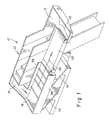
- Figure 1 is a perspective view of the parts feeder of the present invention with the electromagnetic actuator and associated support structure removed therefrom for simplicity.
- Figure 2 is a schematic cross-sectional schematic view of the storage bin and reciprocating plate parts elevator section of the apparatus depicted in Figure 1.
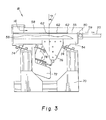
- Figure 3 is a side elevational view of the vibratory conveyor section of the apparatus depicted in Figure 1 with a sidewall partially removed therefrom.
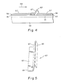
- Figure 4 is a side elevational view of a portion of the vibratory conveyor surface with an exemplary rib projecting therethrough.
- Figure 5 is a perspective view of the exemplary rib shown in Figure 4.
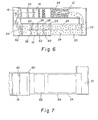
- Figure 6 is a top plan view schematic of the apparatus depicted in Figure 1 illustrating parts distribution density in the conveyance loop formed by the apparatus of Figure 1.
- Figure 7 is a top plan view of the continuous belt conveyor section of the apparatus of Figure 1.
- Turning first to Figure 1, there is shown a perspective view of the
flexible parts feeder 10 of the present invention. Theflexible parts feeder 10 includes astorage bin 12 which serves to hold the reservoir of parts. Parts are removed fromstorage bin 12 with a reciprocating plateparts elevator section 14 which will be described more fully hereinafter. The reciprocating plateparts elevator section 14 delivers parts to chute 16.Chute 16 is mounted tovibratory conveyor 18 and is inclined such that parts delivered thereto slide downchute 16 and ontovibratory conveyor 18. Parts conveyed along the length ofvibratory conveyor 18 are delivered tobelt conveyor 20 which is a typical endless loop belt conveyor system. As will be discussed in more detail hereinafter, a portion ofbelt conveyor 20 is in the field of view of an image capturing means (not shown) which may be used for inspection and/or identification of parts. Also not shown is a robot which "picks" the desired parts frombelt conveyor 20. Parts not picked frombelt conveyor 20 fall therefrom intotrough 22. Such parts slide downtrough 22 intostorage bin 12. In such manner, parts not picked by the robot are recirculated throughapparatus 10 such that they will once again pass through the camera's field of view onbelt conveyor 20. - Looking next at Figure 2, there is schematically depicted a cross-sectional view of the
storage bin 12 and reciprocating plateparts elevator section 14. As can be seen, a plurality of randomly orientedparts 24 reside instorage bin 12 which are introduced thereto through the open top ofstorage bin 12. The randomly orientedparts 24 may all be identical parts, or may be two or more different types of parts. Thebottom wall 26 ofstorage bin 12 is inclined towardelevator section 14. Thesidewalls 28 ofstorage bin 12 may also be inclined toward thebase 30 ofbottom wall 26. In such manner, theparts 24 are funneled toward the base 30 to press against thefront face 32 ofbulk elevator 34.Bulk elevator 34 is preferably supported bylinear bearings 36 and is preferably actuated by a reversinglead screw 38, abelt 40 and amotor 42.Bulk elevator 34 is driven in a reciprocating motion bymotor 42 such that on downward movement, a plurality ofparts 24 fall by gravity onto thetop surface 44 ofbulk elevator 34. On its upward stroke,bulk elevator 34 rises to a level such that thetop surface 44 is substantially even with thetop surface 46 ofstationary platform 48. Thus, whenbulk elevator 34 reaches the peak of its upward stroke, theparts 24 supported thereon fall by gravity onto thetop surface 46 of stagingplatform 48. Residing adjacent to stagingplatform 48 is areciprocating plate conveyor 50. Reciprocatingplate conveyor 50 is preferably that conveying apparatus taught in U.S. Patent 5,385,227. Such conveying apparatus is manufactured by Omnifeed Systems, Inc., of Emmanaus, Pennsylvania. Reciprocatingplate conveyor 50 includes a series of opposingly reciprocatedplates 52 which are actuated in a synchronized way (by means not shown) such thatparts 24 are taken fromtop surface 46 of stagingplatform 48 and raised and transferred to eachsuccessive reciprocating plate 52 to ultimately deliverparts 24 intochute 16. The rate at whichbulk elevator 34 reciprocates should be adjusted so that there is always some minimum quantity ofparts 24 residing ontop surface 46. It should, of course, reciprocate at a rate which is substantially less than the rate at whichreciprocating plates 52 reciprocate. A portion of thoseparts 24 residing ontop surface 46 then slide onto thelowest reciprocating plate 52 when thatlowest reciprocating plate 52 reaches the bottom of its downstroke during reciprocation. Through a series of transfers between subsequentreciprocating plates 52,parts 24 are elevated to the discharge area to fall intochute 16. The quantity of parts which can be held ontop surface 46 of stagingplatform 48 should be greater than the quantity ofparts 24 which can be held on top of any ofreciprocating plates 52. It is believed that the ratio of the surface area oftop surface 46 to the surface area of the top of areciprocating plate 52 should be in the range of from about 2:1 to about 3:1. The use ofbulk elevator 34 in combination with stagingplatform 48 aid in ensuring that a small and consistent quantity ofparts 24 is fed throughelevator section 14 tochute 16. Further, the use ofbulk elevator 34 results in a decrease in the churning of parts in the lower portion ofstorage bin 12 whenstorage bin 12 is relatively full. Merely extendingreciprocating plate conveyor 50 down into the full depth ofstorage bin 12 would have the disadvantage of having one or morereciprocating plates 52 which at the top of their respective strokes would still be below the level ofparts 24 instorage bin 12. The resulting churning ofparts 24 can potentially damage someparts 24. It should be understood that the series of transfers fromstorage bin 12 tobulk elevator 34 to stagingplatform 48 and to eachsuccessive reciprocating plate 52 tends to detangle the randomly orientedparts 24 from one another in a very gentle way. The rate at whichreciprocating plates 52 reciprocate should be adjusted so that some average desired part feed rate is obtained. - Other elevating-type conveyors may be substituted for reciprocating
plate conveyor 50 and/orbulk elevator 34. One example of such an elevating-type conveyor which could be used to acquireparts 24 fromstorage bin 12 and deliversuch parts 24 tochute 16 is a cleted conveyor belt. - Turning next to Figure 3, there is shown the side elevational schematic of the
vibratory conveyor section 18 of the present invention.Vibratory conveyor section 18 includes a support member orupper frame 54 with a generally planar top surface. The term "generally planar" top surface as used herein is intended to mean a surface comprised of a single surface or multiple surfaces, all of which reside in one plane. In other words, the top surface ofsupport member 54 may be either continuous or discontinuous. An example of asupport member 54 with a discontinuous top surface would be an extruded aluminum structural member with a series of spaced apart, parallel T-shaped sections forming the top surface. A second example of asupport member 54 with a discontinuous top surface would be asupport member 54 comprised of a plurality of spaced apart, parallel I-bars with the top surfaces of the individual I-bars residing in the same plane. The top surface ofsupport member 54 is covered or partially covered with a vibratory surface material which is preferably apile material 55 which includes a base 56 withfibers 57 projecting therefrom (see Figure 4). Bordering each side ofsupport member 54 is aside wall 58 which serves to containparts 24 therebetween.Pile material 55 is preferably Brushlon ® as manufactured by 3M Company of St. Paul, MN. Brushlon ® has fibers which are oriented about 15° to 20° from vertical. Theindividual fibers 57 ofpile material 55 are reoriented in the range of from about 50° to about 80° from vertical by compressing the material while heating. As a result,parts 24 are supported on the sides of the individual fibers or bristles 57 and not on the ends of thebristles 57 as is typical of vibratory conveyors of the prior art. The individual fibers or bristles 57 are all inclined toward the downstream direction and thecontinuous belt conveyor 20 as indicated byarrow 59. Thepile material 55 preferably includes abacker member 60 made of a ferromagnetic sheet metal which is adhered to the underside ofpile material 55. There is amagnetic vinyl sheet 61 which is affixed to supportmember 54. In such manner, thepile material 55 throughbacker member 60 can be magnetically coupled to supportmember 54. This method of coupling thepile material 55 to supportmember 54 provides an easy means to remove and/or replacepile material 55. Further, the magnetic coupling allows for more intimate planar contact between the two members as opposed to the Velcro®-type arrangement typically used to fasten pile material to the surfaces of a vibratory conveyor. It should be understood that the positions ofbacker member 60 andmagnetic vinyl sheet 61 can be reversed. In other words, abacker member 60 made of a ferromagnetic sheet metal can be adhered to thesupport member 54 and themagnetic vinyl sheet 61 can be affixed to the underside ofpile material 55. Further, a second magnetic vinyl sheet could be substituted forbacker member 60. The magnetic coupling arrangement of the present invention results in a more efficient transfer of energy during vibration over Velcro®-type interfaces which generally act to dampen vibration. Further, the magnetic coupling arrangement of the present invention allows for much easier positioning ofpile material 55 than is afforded by Velcro®-type interfaces. Those skilled in the art of vibratory conveyors will recognize that a smooth surfaced material such as steel, plastic or rubber may be substituted forpile material 55. Using a smooth surfaced material will likely require an adjustment of vibration amplitudedepending on thespecific parts 24 being conveyed. - Projecting upward from
support member 54 is at least onerib 62 and preferably, a series ofribs 62. Eachrib 62 preferably traverses the width ofpile material 55 and is preferably generally perpendicular to each ofsidewalls 58. However, it should be understood that eachrib 62 could be formed in two or more sections with a gap between adjacent sections and between the end sections and sidewalls 58. Thus, asingle rib 62 may be formed, for example, by an array of closely spaced, projecting nubs arranged in one or more lines across the width ofpile material 55 wherein the nubs in adjacent lines may be staggered from one another. Any gaps left inribs 62 should preferably be small enough such thatindividual parts 24 could not pass directly therethrough without having to pass over at least a portion ofrib 62. Each ofribs 62 may project to the same height abovepile material 55. However, it is preferred thatribs 62 are arranged in a such way that the height of eachsuccessive rib 62 moving toward the downstream is slightly less than the height of the precedingrib 62. With theribs 62 decreasing in height, less effort is required to get individual parts over eachsuccessive rib 62. Eachrib 62 aids in spreading the individual parts across thewidth pile material 55. Thus, eachrib 62 aids in obtaining a more optimum distribution density of parts for picking by a robot while being less of an obstacle to the forward movement of parts onvibratory conveyor section 18. The term "generally perpendicular" as used herein with reference toribs 62 is intended to includeribs 62 which are perpendicular to each ofsidewalls 58 andribs 62 which are within about 5° of being perpendicular to each ofsidewalls 58, as well asribs 62 formed by arrays of nubs wherein the array of nubs is perpendicular to each ofsidewalls 58, or the array of nubs is within about 5° of being perpendicular to each ofsidewalls 58. - One possible design for
ribs 62 is depicted in Figures 4 and 5. In such exemplary design,rib 62 is constructed from a formedsheet metal strip 64 to create abase portion 63 and an inverted V-shapedportion 65.Rib 62 is retained in place by trappingbase portion 63 betweenbacker member 60 andmagnetic vinyl sheet 61. Thus, ifsheet metal strip 64 is made from a ferromagnetic material, thenrib 62 is both mechanically and magnetically coupled betweenbacker member 60 andmagnetic vinyl sheet 61. Thefront face 67 ofrib 62 may be vertical but preferably resides at an angle of from about 10° to about 30° from vertical toward the direction of flow ofparts 24. Depending the shape and size ofparts 24 being conveyed a verticalfront face 67 may result in trapping someparts 24. The actual height ofribs 62 should be determined empirically for thespecific parts 24 being conveyed. - Returning to Figure 3,
support member 54 is connected tolower frame 70 by means offlexures 74. Extending fromsupport member 54 isbracket 76.Electromagnetic actuator 72 is connected tobracket 76 viaflexures 78 and is thus suspended fromsupport member 54. Flexures 74 andflexures 78 are preferably oriented such that they reside at an angle in the range of from about 10° to about 30° from the horizontal. This results in an angle of vibration ofsupport member 54 in the range of from about 10° to about 30° from vertical. Flexures 74 andflexures 78 which are generally equivalent to leaf springs are preferably made from Scotchply ® (which is a non-woven, fiberglass reinforced, epoxy resin material) as manufactured by 3M of St. Paul, MN. Other materials such as steel may be used. Throughelectromagnetic actuator 72,support member 54 andpile material 55 affixed thereon is vibrated in a more vertical direction than typical vibratory conveyors of the prior art. One suitableelectromagnetic actuator 72 for use with the present invention is the F-T01A electromagnetic actuator as manufactured by the FMC Material Handling Equipment Division, Homer City, PA. It is available as a unit complete withflexures 78. Those skilled in the art will recognize thatelectromagnetic actuator 72 will include means for adjusting the amplitude of vibration imparted tovibratory conveyor 18. Through the proper adjustment of vibration amplitude most unstable part orientations can be eliminated. - In operation, a quantity of
parts 24 slides downinclined chute 16 through both gravity and the vibrations imparted thereto byelectromagnetic actuator 72. The vibrations transmitted throughpile material 55cause parts 24 received viachute 16 to begin to spread out onpile material 55 and move toward thefirst rib 62. The more vertical direction of the vibration tends to spread out theparts 24 more effectively without increasing the speed of theparts 24 as they are conveyed over thepile material 55. Further, it should be appreciated that the relatively flat angle at which the individual fibers are oriented onpile material 56 substantially eliminates the risk of parts becoming stuck or lodged in thepile material 56 as can sometimes occur when conveyingparts 24 possessing sharp features over a pile material with fibers which are more vertically oriented. - Each
rib 62 creates a partial flow obstruction ofparts 24 moving alongpile material 55 towardbelt conveyor 20. This flow obstruction results in an accumulation ofparts 24 just upstream of eachrib 62 which causesparts 24 to further spread widthwise acrosspile material 55. It should also be noted that the flow obstructions created byrib 62 provide a means to control the flow ofparts 24 throughvibratory conveyor 18 regardless of part size. Preferably, the height of eachrib 62 and the vibration amplitude imparted toplanar member 54 are chosen in a way that will cause the greatest flow obstruction at thefirst rib 62, a lesser flow obstruction at thesecond rib 62, and so on such that, with each successive rib, the flow obstruction lessens. Thus, if the vibration amplitude is consistent acrossplanar member 54, the height of thefirst rib 62 would be the greatest with eachsubsequent rib 62 decreasing in height. It should be understood that the more vertically oriented vibration direction maximizes the effectiveness ofribs 62. The spacing betweenadjacent ribs 62 should be chosen based on the expected average accumulation ofparts 24 at eachrib 62. This can, of course, be determined empirically. Theparts 24 will separate from one another thereby minimizing the amount ofparts 24 overlapping one another. Overlappingparts 24 are not "pickable" and will therefore be recirculated. By helping to spread outparts 24 across the width ofvibratory conveyor 18,ribs 62 create a more uniform distribution of separatedparts 24. This results in an increase in the rate of flow of "pickable"parts 24. This is illustrated in Figure 6 which is a top plan view schematic showing part distribution density through the conveyance loop ofapparatus 10. Note that there is shownparts 24 gathering at eachsuccessive rib 62. This gathering is what causes spreading ofparts 24 across the width ofvibratory conveyor 18. With eachsuccessive rib 62 getting shorter, the "gathering" ofparts 24 decreases ultimately leading to the desired more uniform density ofparts 24 on the last section ofvibratory conveyor 18 just before transfer to thebelt conveyor 20. It will be appreciated that for a given series ofribs 62, the vibration amplitude of theplanar member 54 may be adjusted to better achieve the desired average accumulation ofparts 24 at eachrib 62. A larger vibration amplitude results in a overall decrease in average accumulation of parts at eachrib 62 and a smaller vibration amplitude results in an overall increase in average accumulation of parts in at eachrib 62. - At the exit of the
vibratory conveyor 18,parts 24 are moved across atransition plate 80 and ontobelt conveyor 20 due to the vibrations caused byelectromagnetic actuator 72.Transition plate 80 preferably has a minimal elevation change such that its length in the direction of flow is as short as possible and its angle of incline fromtransition plate 80 down tobelt conveyor 20 is not more than about 5°. The short length and minimal elevation change oftransition plate 80 allowsparts 24 to be transferred without significantly affecting individual part orientation and separation. The velocity ofbelt conveyor 20 should be greater than or equal to the average speed ofparts 24 traveling onvibratory conveyor 18.Belt conveyor 20 is preferably traveling at a relatively slow velocity such as about one inch per second (1"/sec) for the purpose of inspection and picking. The speed ofbelt conveyor 20 may, of course be increased to thereby further increase flow rate ofparts 24. However, operatingbelt conveyor 24 at higher speeds will likely require a more expensive strobe lighting system forviewing parts 24 with the image capture means (not shown). Preferably,conveyor belt 20 is driven at a constant speed by a motor (not shown) and not in an indexing motion. If any starting and stopping ofconveyor belt 20 is required, it should be done in such a manner that does not create any undesirable instability ofparts 24 resting onbelt conveyor 20. Those skilled in the art will recognize thatbelt conveyor 20 will also have associated therewith an encoder (not shown) which allows monitoring of incremental belt movement. - Looking next at Figure 7, there is shown a top plan view of the
belt conveyor section 20.Dotted line 82 represents the inspection field of view of the camera or other image capture means (not shown).Dotted line 84 represents the pick area from which the robot (not shown) picksparts 24 traveling onconveyor 20. The inspection camera (not shown) is preferably directed perpendicular to thebelt conveyor 20. Examples of lighting and image capture systems which are particularly useful in combination with the present invention are disclosed in U.S. Patent Application Serial No. 08/991,491 entitled, "Inspection Method and Apparatus for Determining the Side-up Orientation of an Object Resting on a Flat Surface" and U.S. Patent Application Serial No. 08/991,728 entitled, "Mehtod and Apparatus for Determining Orientation of Parts Resting on a Flat Surface" both filed on December 16, 1997, which are hereby incoroporated herein by reference. The combination ofvibratory conveyor 18,transition plate 80 andbelt conveyor 24 provide an advantage in delivering separatedparts 24 to an inspection field ofview 82 in stable orientations. This advantage is significantly enhanced with the incorporation ofribs 62 into thevibratory conveyor 18. -
Parts 24 pass into the field ofview 82 for inspection. Location information of all parts determined to be "pickable" is sent to the robot controller. The encoder allows for monitoring of all belt and part movement between the time of inspection and the time of grasping or picking.Parts 24 then pass into thepick area 84 where the robot grasps at least a portion of theparts 24 that have been inspected and determined to be "pickable". Anyparts 24 which are not picked by the robot continue to move alongbelt conveyor 20 to fall intotrough 22 and, as such, are returned tostorage bin 12. - Using the
vibratory conveyor 18 of the present invention in combination withbelt conveyor 20 enables separatedparts 24 to be delivered to the field ofview 82 far in excess of the conveyors of the prior art.Separated parts 24 can be delivered to the field ofview 82 at rates ranging up to 60 to 100 parts per minute, or even higher. The automated process (whether it be inspection, robotic assembly, and/or part classification, etc.) in which the conveying system is being used is no longer limited by the rate at which usable parts are presented. Rather, the overall process becomes limited by the speed of the downstream activities. Thus, for example, if the separatedparts 24 are being acquired from thepick area 84 for assembly, the speed of the assembly process will be limited by the speed of the robot and not by the rate at which separatedparts 24 pass into thepick area 84. - Due to the conveyance nature of the
vibratory conveyor 18 andtransition plate 80, the majority ofparts 24 passing into the inspection area or field ofview 82 possess orientations which are relatively stable thereby minimizing the number of likely orientations for eachindividual part 24. Minimizing the number of likely orientations increases the speed at which at whichparts 24 can be inspected and/or identified for picking. If a less stable part orientation is desired for inspection and grasping by a robot, a change in elevation betweentransition plate 80 andbelt conveyor 20 may be incorporated to intentionally and gently "tumble"parts 24 during transfer to beltconveyor 20. - Those skilled in the art will recognize that overall part separations on
belt conveyor 20 may, to some extent, be further increased without adversely affecting the uniformity of part distribution by two means. First, although not preferred,electromagnetic actuator 72 may be quickly cycled on and off to thereby operatevibratory conveyor 18 intermittently. By controllingelectromagnetic actuator 72 in such a manner, a reduction in the overall rate at whichparts 24 are transferred tobelt conveyor 20 is achieved, thus, further increasing overall part separation onbelt conveyor 20. Alternatively,belt conveyor 20 can be driven at a higher constant speed. The higher speed ofbelt conveyor 20 will result in a greater separation of parts supported thereon as they are transferred fromtransition plate 80. As stated above, those skilled in the art will appreciate that increasing the speed ofconveyor belt 20 may require strobe lighting to obtain the sharp image ofparts 24 necessary for inspection and/or picking. - From the foregoing, it will be seen that this invention is one well adapted to attain all of the ends and objects hereinabove set forth together with other advantages which are apparent and which are inherent to the invention.
- It will be understood that certain features and subcombinations are of utility and may be employed with reference to other features and subcombinations. This is contemplated by and is within the scope of the claims.
Claims (10)
- An apparatus for uniformly distributing parts on a conveyor surface:(a) a storage bin for holding randomly oriented parts in bulk;(b) an elevating conveyor adjacent the storage bin, the elevating conveyor acquiring a fragment of the randomly oriented parts in the storage bin, the elevating conveyor elevating the fragment of randomly oriented parts and delivering the fragment of randomly oriented parts to a chute;(c) a vibratory conveyor receiving the fragment of randomly oriented parts from the chute, the vibratory conveyor including at least one rib projecting upward therefrom and extending across at least a section of the vibratory conveyor perpendicular to a direction of conveyance of the vibratory conveyor, the at least one rib acting as a flow obstruction to cause the randomly oriented parts traveling on the vibratory conveyor to gather and spread across a width of the vibratory conveyor, the randomly oriented parts being spread more uniformly on the vibratory conveyor after passing over the at least one rib; and(d) a belt conveyor for receiving the randomly oriented parts from the vibratory conveyor.
- An apparatus as recited in claim 1 further comprising:(a) a camera field of view area and a robot pick area on the belt conveyor; and(b) a trough positioned adjacent a downstream end of the belt conveyor for receiving any of the randomly oriented parts not retrieved fromthe belt conveyor, the trough returning the randomly oriented parts received therein to the storage bin.
- An apparatus as recited in claim 1, the elevating conveyor comprising:(a) a bulk elevator including a top surface, the bulk elevator reciprocating to a low point at which a portion of the randomly oriented parts in the storage bin move by gravity to reside on the top surface; and(b) a staging platform adjacent the bulk elevator, the bulk elevator reciprocating to a high point at which at least some of the portion of the randomly oriented parts transfer by gravity to the staging platform to thereby create a secondary reservoir of randomly oriented parts on the staging platform which is continually restocked by the bulk elevator.
- An apparatus as recited in claim 3, the elevating conveyor further comprising:a reciprocating plate conveyor adjacent the staging platform, the reciprocating plate conveyor acquiring a fragment of the secondary reservoir of the randomly oriented parts, the reciprocating plate conveyor delivering the fragment of randomly oriented parts to the chute.
- A vibratory conveyor for uniformly distributing randomly oriented parts comprising:(a) a support member with a generally planar top surface;(b) means for vibrating the support member;(c) a vibratory surface material supported on the generally planar top surface; and(d) at least one rib projecting upward through the vibratory surface material and extending across at least a section of the support member, the at least one rib being about perpendicular to a direction of conveyance of the vibratory conveyor, the at least one rib acting as a flow obstruction to cause the randomly oriented parts traveling on the vibratory surface material to gather and spread across a width of the planar member, the randomly oriented parts being spread more uniformly on the vibratory surface material after passing over the at least one rib.
- A vibratory conveyor as recited in claim 5 further comprising:a backer member affixed to an underside of the vibratory surface material.
- A vibratory conveyor as recited in claim 5 wherein:
the rib includes a front face which is oriented at an angle of from about 10° to about 30° from vertical. - A vibratory conveyor as recited in claim 5 wherein:
the vibratory surface material is a pile material which includes a surface of fibers, the fibers oriented in a range of from about 50° to about 80° from vertical. - An apparatus as recited in claim 1, the vibratory conveyor comprising:(a) a pile material; and(b) a backer member affixed to an underside of the pile material.
- An apparatus for uniformly distributing parts comprising:(a) a vibratory conveyor for receiving a plurality of randomly oriented parts;(b) a belt conveyor for receiving the randomly oriented parts from the vibratory conveyor; and(c) a short transition plate between the vibratory conveyor and the belt conveyor over which the randomly oriented parts must pass to be transferred from the vibratory conveyor to the belt conveyor.
Applications Claiming Priority (2)
| Application Number | Priority Date | Filing Date | Title |
|---|---|---|---|
| US09/026,078 US6116409A (en) | 1998-02-19 | 1998-02-19 | Conveyor for uniformly distributing parts |
| US26078 | 1998-02-19 |
Publications (2)
| Publication Number | Publication Date |
|---|---|
| EP0937667A2 true EP0937667A2 (en) | 1999-08-25 |
| EP0937667A3 EP0937667A3 (en) | 2001-04-04 |
Family
ID=21829758
Family Applications (1)
| Application Number | Title | Priority Date | Filing Date |
|---|---|---|---|
| EP99200356A Withdrawn EP0937667A3 (en) | 1998-02-19 | 1999-02-08 | Method and apparatus to uniformly distribute bulk conveyed parts for inspection by a camera |
Country Status (3)
| Country | Link |
|---|---|
| US (2) | US6116409A (en) |
| EP (1) | EP0937667A3 (en) |
| JP (1) | JPH11314724A (en) |
Cited By (4)
| Publication number | Priority date | Publication date | Assignee | Title |
|---|---|---|---|---|
| US6216850B1 (en) * | 1999-05-26 | 2001-04-17 | Paul A. Svejkovsky | Cyclically powered conveyor with flow leveler |
| CN103496567A (en) * | 2013-10-18 | 2014-01-08 | 深圳市深立精机科技有限公司 | Automatic feeding device |
| CN104555352A (en) * | 2013-10-21 | 2015-04-29 | 泰科电子(上海)有限公司 | Automatic feed system |
| EP2114800A4 (en) * | 2007-03-01 | 2017-05-24 | Key Technology, Inc. | Manufacturing device for use with a vibratory conveyor, and method for manufacturing a product |
Families Citing this family (27)
| Publication number | Priority date | Publication date | Assignee | Title |
|---|---|---|---|---|
| US6116409A (en) * | 1998-02-19 | 2000-09-12 | Eastman Kodak Company | Conveyor for uniformly distributing parts |
| CA2270484C (en) | 1999-04-27 | 2000-10-17 | Maxi-Tour Inc. | Article transfer device |
| EP1051063A1 (en) * | 1999-05-07 | 2000-11-08 | Mikron SA Boudry | Parts feeding device |
| US6481560B2 (en) * | 2000-06-08 | 2002-11-19 | Christopher L. Kearney | Robotic feeding system |
| JP4061085B2 (en) * | 2002-02-07 | 2008-03-12 | Ykk株式会社 | Parts feeding device |
| DE10211976A1 (en) * | 2002-03-19 | 2003-10-02 | Bosch Gmbh Robert | Method and device at least for the sterilization of containers and / or their closing elements |
| NL1022679C1 (en) * | 2003-02-14 | 2004-08-17 | Dijkstra Vereenigde Bedrijven | Inspection device for loose objects, such as tablets. |
| US6845862B2 (en) * | 2003-03-31 | 2005-01-25 | Mark P. Southwick | Portable sawmill conveyor system |
| US7754984B2 (en) * | 2005-01-20 | 2010-07-13 | Ishida Co., Ltd. | Transportation device and combinational weighing apparatus including the same |
| US7399383B2 (en) * | 2005-07-22 | 2008-07-15 | Roboshop, Inc. | Vibratory conveyor with non-biased oscillation |
| WO2008055244A2 (en) | 2006-10-31 | 2008-05-08 | Sensient Colors Inc. | Modified pigments and methods for making and using the same |
| WO2009026552A2 (en) | 2007-08-23 | 2009-02-26 | Sensient Colors Inc. | Self-dispersed pigments and methods for making and using the same |
| US7571800B2 (en) * | 2007-10-30 | 2009-08-11 | Stork Townsend Inc. | Vibrating alignment conveyor |
| CN101652058A (en) * | 2008-08-13 | 2010-02-17 | 深圳富泰宏精密工业有限公司 | Conveyor device |
| US9221986B2 (en) | 2009-04-07 | 2015-12-29 | Sensient Colors Llc | Self-dispersing particles and methods for making and using the same |
| US8474597B2 (en) | 2011-03-22 | 2013-07-02 | Nordco Inc. | Tray for orienting and conveying items |
| US8516965B2 (en) * | 2011-03-22 | 2013-08-27 | Nordco Inc. | Automatic spike feeder system |
| US8857344B2 (en) | 2011-03-22 | 2014-10-14 | Nordco Inc. | Automatic spike feeder system |
| US8985307B2 (en) * | 2011-03-22 | 2015-03-24 | Nordco Inc. | Singulator for sorting random items |
| CN104220350B (en) * | 2012-01-31 | 2016-12-14 | Abb研究有限公司 | Method and system for feed element |
| CN104203493A (en) * | 2012-04-02 | 2014-12-10 | 株式会社安川电机 | Production system and manufacturing method for processed products |
| DE102014213639A1 (en) * | 2014-07-14 | 2016-01-14 | Robert Bosch Gmbh | Vibratory chute and vibratory conveyor for transporting shingled products in food production |
| US9969566B1 (en) | 2016-11-15 | 2018-05-15 | Nordco Inc. | Magnetic singulator for bulk rail fasteners |
| JP6564426B2 (en) * | 2017-07-07 | 2019-08-21 | ファナック株式会社 | Parts supply device and machine learning device |
| CH714498A2 (en) * | 2017-12-21 | 2019-06-28 | Eta Sa Mft Horlogere Suisse | Controlled distribution system of components. |
| JP2019209276A (en) * | 2018-06-06 | 2019-12-12 | 日本協同企画株式会社 | Waste material sorting method and waste material sorting device |
| CN116767804B (en) * | 2023-07-25 | 2024-01-16 | 南京明盛制冷科技有限公司 | Automatic pipe fitting sequencing device for processing refrigeration copper pipe |
Citations (7)
| Publication number | Priority date | Publication date | Assignee | Title |
|---|---|---|---|---|
| US3995733A (en) * | 1971-04-26 | 1976-12-07 | Lipe-Rollway Corporation | Vibratory pile conveyor system |
| US4457840A (en) * | 1981-07-27 | 1984-07-03 | Voest-Alpine Aktiengesellschaft | Apparatus for delivering a stream of green pellets |
| US4537300A (en) * | 1982-05-03 | 1985-08-27 | Farmatic S.R.L. | Apparatus for selecting and supplying capsules or like round articles of deformable material to the feed hopper of machines for handling these articles |
| US4819784A (en) * | 1982-10-25 | 1989-04-11 | Stiwa-Fertigungstechnik Sticht Gesellschaft M.B.H. | Arrangement for feeding parts |
| US5314055A (en) * | 1990-08-25 | 1994-05-24 | Intelligent Automation Systems, Inc. | Programmable reconfigurable parts feeder |
| US5558199A (en) * | 1993-07-31 | 1996-09-24 | Hauni Maschinenbau Aktiengesellschaft | Apparatus for forming a layer of tobacco particles |
| US5647472A (en) * | 1994-04-20 | 1997-07-15 | Fierkens; Richard H. J. | Automatic pellet feeding apparatus for use in forming encapsulated semiconductor chips and method therefor |
Family Cites Families (24)
| Publication number | Priority date | Publication date | Assignee | Title |
|---|---|---|---|---|
| US3150005A (en) * | 1958-09-22 | 1964-09-22 | Corn Products Co | Machine for treating particulate solids |
| US3224553A (en) * | 1963-02-27 | 1965-12-21 | Milford A Campbell | Vibratory work feeding and orienting unit |
| US3193080A (en) * | 1963-04-08 | 1965-07-06 | Speaker Sortation Systems Inc | Multiple station feeding means |
| GB1057745A (en) * | 1963-04-23 | 1967-02-08 | Willem De Ridder | Apparatus for transferring bakery pans from a delivery conveyor to a transverse conveyor |
| GB1122596A (en) * | 1965-07-20 | 1968-08-07 | Wharton Engs Elstree Ltd | Improvements relating to vibratory and oscillatory conveyors |
| US3667590A (en) * | 1970-01-02 | 1972-06-06 | Dennis E Mead | Vibratory pile feeder |
| US3648828A (en) * | 1970-12-31 | 1972-03-14 | Horace Mccaffrey Jr | Vibratory conveyor |
| US3841471A (en) * | 1971-04-27 | 1974-10-15 | Lipe Rollway Corp | Feeder and orienter |
| BE791991A (en) * | 1972-08-31 | 1973-03-18 | Fertilizantes De Iberia S A Fe | SETTING DEVICE |
| UST927006I4 (en) * | 1973-08-24 | 1974-10-01 | Plural conveyors with air cushioned transfer chute | |
| US3929221A (en) * | 1974-04-11 | 1975-12-30 | Lipe Rollway Corp | Paper sheet conveyor |
| US4037710A (en) * | 1974-07-11 | 1977-07-26 | Lipe-Rollway Corporation | Accumulator for object feeder |
| US4068029A (en) * | 1976-03-29 | 1978-01-10 | Lipe Rollway Corporation | Molded resilient element for vibratory feeder |
| CH622084A5 (en) * | 1977-07-14 | 1981-03-13 | Schenck Ag Carl | |
| AT369891B (en) * | 1981-07-27 | 1983-02-10 | Voest Alpine Ag | DEVICE FOR LOADING WALKING GRIDS WITH GREEN PELLETS |
| AT370654B (en) * | 1981-10-05 | 1983-04-25 | Voest Alpine Ag | DEVICE FOR THE DOSED CHARGING OF A CONTINUOUS CHOCOLATE WITH CASTING POWDER |
| DE3602773A1 (en) * | 1986-01-30 | 1987-08-06 | Bosch Gmbh Robert | DEVICE FOR STORING AND FEEDING SMALL PARTS |
| US5120190A (en) * | 1987-10-22 | 1992-06-09 | General Motors Corporation | Parts assembly kitting apparatus and method |
| US5069329A (en) * | 1987-10-22 | 1991-12-03 | General Motors Corporation | Parts feeder |
| GB2223998B (en) * | 1988-09-12 | 1992-03-04 | British Nuclear Fuels Plc | A transfer method and apparatus therefor |
| US5301791A (en) * | 1992-10-07 | 1994-04-12 | Lipe-Rollway Automation Equipment Div. Of Lipe-Rollway Corp. | Vibratory pile conveyor system |
| US5385227A (en) * | 1993-07-29 | 1995-01-31 | Marsh; Robert A. | Elevating conveyor for small articles |
| US5613595A (en) * | 1995-04-19 | 1997-03-25 | See-Chang Ting | Automatic slope fruit feeding machine used with a fruit grading machine |
| US6116409A (en) * | 1998-02-19 | 2000-09-12 | Eastman Kodak Company | Conveyor for uniformly distributing parts |
-
1998
- 1998-02-19 US US09/026,078 patent/US6116409A/en not_active Expired - Fee Related
-
1999
- 1999-02-08 EP EP99200356A patent/EP0937667A3/en not_active Withdrawn
- 1999-02-19 JP JP11040857A patent/JPH11314724A/en active Pending
-
2000
- 2000-04-21 US US09/556,856 patent/US6257395B1/en not_active Expired - Fee Related
Patent Citations (7)
| Publication number | Priority date | Publication date | Assignee | Title |
|---|---|---|---|---|
| US3995733A (en) * | 1971-04-26 | 1976-12-07 | Lipe-Rollway Corporation | Vibratory pile conveyor system |
| US4457840A (en) * | 1981-07-27 | 1984-07-03 | Voest-Alpine Aktiengesellschaft | Apparatus for delivering a stream of green pellets |
| US4537300A (en) * | 1982-05-03 | 1985-08-27 | Farmatic S.R.L. | Apparatus for selecting and supplying capsules or like round articles of deformable material to the feed hopper of machines for handling these articles |
| US4819784A (en) * | 1982-10-25 | 1989-04-11 | Stiwa-Fertigungstechnik Sticht Gesellschaft M.B.H. | Arrangement for feeding parts |
| US5314055A (en) * | 1990-08-25 | 1994-05-24 | Intelligent Automation Systems, Inc. | Programmable reconfigurable parts feeder |
| US5558199A (en) * | 1993-07-31 | 1996-09-24 | Hauni Maschinenbau Aktiengesellschaft | Apparatus for forming a layer of tobacco particles |
| US5647472A (en) * | 1994-04-20 | 1997-07-15 | Fierkens; Richard H. J. | Automatic pellet feeding apparatus for use in forming encapsulated semiconductor chips and method therefor |
Cited By (5)
| Publication number | Priority date | Publication date | Assignee | Title |
|---|---|---|---|---|
| US6216850B1 (en) * | 1999-05-26 | 2001-04-17 | Paul A. Svejkovsky | Cyclically powered conveyor with flow leveler |
| EP2114800A4 (en) * | 2007-03-01 | 2017-05-24 | Key Technology, Inc. | Manufacturing device for use with a vibratory conveyor, and method for manufacturing a product |
| CN103496567A (en) * | 2013-10-18 | 2014-01-08 | 深圳市深立精机科技有限公司 | Automatic feeding device |
| CN103496567B (en) * | 2013-10-18 | 2016-03-02 | 深圳市深立精机科技有限公司 | A kind of automatic charging device |
| CN104555352A (en) * | 2013-10-21 | 2015-04-29 | 泰科电子(上海)有限公司 | Automatic feed system |
Also Published As
| Publication number | Publication date |
|---|---|
| EP0937667A3 (en) | 2001-04-04 |
| US6116409A (en) | 2000-09-12 |
| JPH11314724A (en) | 1999-11-16 |
| US6257395B1 (en) | 2001-07-10 |
Similar Documents
| Publication | Publication Date | Title |
|---|---|---|
| US6116409A (en) | Conveyor for uniformly distributing parts | |
| CN1223410C (en) | Device for sorting based on color | |
| KR101977694B1 (en) | Singulator conveyor system for rigid parcels and large bags of small parcels | |
| CN109704003B (en) | Feeding system | |
| US20050199470A1 (en) | Transport of bulk material items | |
| CN111282838B (en) | Grain-by-grain seed metering device and seed sorting system | |
| CN111517098B (en) | Vacuum glass support separating and arranging device and method | |
| US20080149460A1 (en) | Textile separating apparatus | |
| CN107497688A (en) | A kind of potato sorting unit | |
| US5123516A (en) | Article conveying and orienting apparatus | |
| EP0527640B1 (en) | Improvements in or relating to a device for feeding objects | |
| US20070017784A1 (en) | Vibratory conveyor with non-biased oscillation | |
| US5931309A (en) | Magnetic separator with inclined conveyance | |
| JP2000343044A (en) | Object feeding device | |
| US5301791A (en) | Vibratory pile conveyor system | |
| CN206705115U (en) | Color selector charging gear | |
| CN208731871U (en) | A kind of material clamp structure and plate material transportation system | |
| CN114318509B (en) | Silicon material treatment device, silicon rod production equipment and silicon material treatment method | |
| JP2000118673A (en) | Alignment supply device for articles | |
| WO1999014139A1 (en) | Conical disc and associated delivery conveyor | |
| CN210847257U (en) | Automatic sorting device | |
| CN1543306A (en) | Electronic component assembly line material supplying device and assembly line comprising material supplying device | |
| CN114212460A (en) | Novel efficient belt type bucket elevator with circulating feeding and controllable tensioning force | |
| US4703846A (en) | Method and apparatus for arranging fragmentary particles into a row consisting of individual particles | |
| CA2198763A1 (en) | Modular frame vibratory pile flexible feeder system |
Legal Events
| Date | Code | Title | Description |
|---|---|---|---|
| PUAI | Public reference made under article 153(3) epc to a published international application that has entered the european phase |
Free format text: ORIGINAL CODE: 0009012 |
|
| AK | Designated contracting states |
Kind code of ref document: A2 Designated state(s): DE FR GB |
|
| AX | Request for extension of the european patent |
Free format text: AL;LT;LV;MK;RO;SI |
|
| PUAL | Search report despatched |
Free format text: ORIGINAL CODE: 0009013 |
|
| AK | Designated contracting states |
Kind code of ref document: A3 Designated state(s): AT BE CH CY DE DK ES FI FR GB GR IE IT LI LU MC NL PT SE |
|
| AX | Request for extension of the european patent |
Free format text: AL;LT;LV;MK;RO;SI |
|
| 17P | Request for examination filed |
Effective date: 20010912 |
|
| AKX | Designation fees paid |
Free format text: DE FR GB |
|
| 17Q | First examination report despatched |
Effective date: 20011207 |
|
| STAA | Information on the status of an ep patent application or granted ep patent |
Free format text: STATUS: THE APPLICATION IS DEEMED TO BE WITHDRAWN |
|
| 18D | Application deemed to be withdrawn |
Effective date: 20020319 |