EP0937631A2 - Automobile body frame - Google Patents
Automobile body frame Download PDFInfo
- Publication number
- EP0937631A2 EP0937631A2 EP99301234A EP99301234A EP0937631A2 EP 0937631 A2 EP0937631 A2 EP 0937631A2 EP 99301234 A EP99301234 A EP 99301234A EP 99301234 A EP99301234 A EP 99301234A EP 0937631 A2 EP0937631 A2 EP 0937631A2
- Authority
- EP
- European Patent Office
- Prior art keywords
- cross member
- automobile body
- body frame
- hollow beam
- frame according
- Prior art date
- Legal status (The legal status is an assumption and is not a legal conclusion. Google has not performed a legal analysis and makes no representation as to the accuracy of the status listed.)
- Granted
Links
Images


Classifications
-
- B—PERFORMING OPERATIONS; TRANSPORTING
- B62—LAND VEHICLES FOR TRAVELLING OTHERWISE THAN ON RAILS
- B62D—MOTOR VEHICLES; TRAILERS
- B62D21/00—Understructures, i.e. chassis frame on which a vehicle body may be mounted
- B62D21/15—Understructures, i.e. chassis frame on which a vehicle body may be mounted having impact absorbing means, e.g. a frame designed to permanently or temporarily change shape or dimension upon impact with another body
- B62D21/157—Understructures, i.e. chassis frame on which a vehicle body may be mounted having impact absorbing means, e.g. a frame designed to permanently or temporarily change shape or dimension upon impact with another body for side impacts
-
- B—PERFORMING OPERATIONS; TRANSPORTING
- B62—LAND VEHICLES FOR TRAVELLING OTHERWISE THAN ON RAILS
- B62D—MOTOR VEHICLES; TRAILERS
- B62D21/00—Understructures, i.e. chassis frame on which a vehicle body may be mounted
- B62D21/10—Understructures, i.e. chassis frame on which a vehicle body may be mounted in which the main member is plate-like
-
- B—PERFORMING OPERATIONS; TRANSPORTING
- B62—LAND VEHICLES FOR TRAVELLING OTHERWISE THAN ON RAILS
- B62D—MOTOR VEHICLES; TRAILERS
- B62D21/00—Understructures, i.e. chassis frame on which a vehicle body may be mounted
- B62D21/15—Understructures, i.e. chassis frame on which a vehicle body may be mounted having impact absorbing means, e.g. a frame designed to permanently or temporarily change shape or dimension upon impact with another body
- B62D21/152—Front or rear frames
-
- B—PERFORMING OPERATIONS; TRANSPORTING
- B62—LAND VEHICLES FOR TRAVELLING OTHERWISE THAN ON RAILS
- B62D—MOTOR VEHICLES; TRAILERS
- B62D25/00—Superstructure or monocoque structure sub-units; Parts or details thereof not otherwise provided for
- B62D25/02—Side panels
- B62D25/025—Side sills thereof
-
- B—PERFORMING OPERATIONS; TRANSPORTING
- B62—LAND VEHICLES FOR TRAVELLING OTHERWISE THAN ON RAILS
- B62D—MOTOR VEHICLES; TRAILERS
- B62D25/00—Superstructure or monocoque structure sub-units; Parts or details thereof not otherwise provided for
- B62D25/20—Floors or bottom sub-units
- B62D25/2009—Floors or bottom sub-units in connection with other superstructure subunits
- B62D25/2018—Floors or bottom sub-units in connection with other superstructure subunits the subunits being front structures
-
- B—PERFORMING OPERATIONS; TRANSPORTING
- B62—LAND VEHICLES FOR TRAVELLING OTHERWISE THAN ON RAILS
- B62D—MOTOR VEHICLES; TRAILERS
- B62D25/00—Superstructure or monocoque structure sub-units; Parts or details thereof not otherwise provided for
- B62D25/20—Floors or bottom sub-units
- B62D25/2009—Floors or bottom sub-units in connection with other superstructure subunits
- B62D25/2036—Floors or bottom sub-units in connection with other superstructure subunits the subunits being side panels, sills or pillars
-
- B—PERFORMING OPERATIONS; TRANSPORTING
- B62—LAND VEHICLES FOR TRAVELLING OTHERWISE THAN ON RAILS
- B62D—MOTOR VEHICLES; TRAILERS
- B62D29/00—Superstructures, understructures, or sub-units thereof, characterised by the material thereof
- B62D29/008—Superstructures, understructures, or sub-units thereof, characterised by the material thereof predominantly of light alloys, e.g. extruded
Abstract
Description
- The present invention relates to an automobile body frame.
- An automobile body frame of a space frame type comprising welded hollow members is generally such that front side frames extend on the respective inner sides of the front wheels, side sills extend on the respective sides of a passenger space floor, and the rear ends of the front side frames and the front ends of the side sills are all connected to a dash board lower cross member. In such an arrangement, the coupling locations at which the front side frames and the side sills are connected to the dash board lower cross member are respectively set in offset positions in the width direction of the automobile. As a result, if the automobile undergoes a head-on collision, input positions where the crashing load applied from the front side frame and the counterforce load applied from the side sill are applied to the dash board lower cross member, are shifted relative to each other.
Accordingly, the coupling regions where the front side frames and the dash board lower cross member are connected together tend to bend easily toward the interior of the passenger space. - It is undesirable for any deformation of the automobile body to intrude into the passenger space, and the rigidity of the passenger space floor has therefore been increased by enlarging the sectional areas of the dash board lower cross member and the side sills. However, if the sizes of these parts are increased, comfort in the passenger space and ease of boarding and alighting are reduced.
- Further, there is another problem in the case of a side impact. In order to protect a passenger from a side impact, a center pillar must be restrained from intruding into the passenger space. Consequently, the bending rigidity of the coupling between the center pillar and a side sill should be increased. Hence, a relatively greater sectional area is normally given to the side sill, which again may result in reduced ease of boarding and alighting.
- In an automobile body frame according to one aspect of the present invention, a hollow beam formed by extrusion molding from a light metal material is used to connect the rear end of a front side frame to the side end of a rear cross member. In consequence, load applied to the front side frame as a result of a head-on collision is received by the hollow beam extending longitudinally of the passenger space, so that the aforementioned intrusion of the dash board lower cross member into the passenger space is avoided. Desired rigidity can be obtained without increasing the thickness of the passenger space floor, by forming the hollow beam as a quadrilateral having a cross sectional shape whose width is smaller than its height and joining the facing inner surfaces of upper and lower walls of the hollow beam by a rib. Moreover, the rigidity of the joint between the hollow beam and the rear cross member can be increased further by connecting the rear end of the hollow beam and the side end of the rear cross member to an outrigger.
- In an automobile body frame according to another aspect of the invention, a hollow beam formed by extrusion molding from a light metal material is used to connect the rear end of a front side frame to the side end of a rear cross member on the inner side of a side sill, and a sheet rail bracket formed by die casting is used to connect the center pillar coupling portion of the side sill to the hollow beam. With this arrangement, the sectional area of the side sill may be reduced, since a load applied to the center pillar is received by both the side sill and the hollow beam. Moreover, no special highly rigid member is required as a coupling member since the side sill and the hollow beam are connected together by means of the sheet rail bracket.
- Two embodiments of the invention will now be described by way of example and with reference to the accompanying drawings, in which:-
- Fig. 1 is a perspective view of an automobile body frame according to a first embodiment of the present invention;
- Fig. 2 is a perspective view of part of the frame, showing the connection of each member to an outrigger;
- Fig. 3 is a sectional view of a floor beam;
- Fig. 4 is a perspective view of an outrigger;
- Fig. 5 shows the connection of a rear trailing arm to the outrigger;
- Fig. 6 is a perspective view of an automobile body frame according to a second embodiment of the present invention;
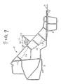
- Fig. 7 is a sectional view taken along line II-II in Fig. 6; and
- Fig. 8 is an enlarged perspective view of the arrangement of a sheet rail bracket in the embodiment of Fig. 6.
-
- Referring to Fig. 1, the frame is formed by welding together various members made of aluminum alloy, and comprises a pair of front side frames 2, a pair of
rear side frames 4, a pair ofside sills 5, afloor tunnel 6, a middle cross member 7, a pair of floor beams 8 (which are hollow beams),sheet rail brackets 9, and anoutrigger 10. - The front side frames 2 extend forward, and rear ends thereof are joined to a dash board lower cross member 1. The
rear side frames 4 extend rearward, and front ends thereof are joined to arear cross member 3. Theside sills 5 extend in the longitudinal direction so as to couple the respective side ends of the dash board lower cross member 1 and therear cross members 3. Thefloor tunnel 6 extends in the longitudinal direction and couples the central portions of the dash board lower cross member 1 and therear cross member 3. The middle cross member 7 couples the side sills 5 in the longitudinally intermediate region of a passenger space. Each of thefloor beams 8 couples the joint between the front side frame 2 and the dash board lower cross member 1 to the side end of therear cross member 3. Thefloor beams 8 are disposed so that the distance between them gradually increases in the rearward direction. Thesheet rail brackets 9 are located to the rear of the middle cross member 7 and couple theside sills 5 to the respectivehollow beams 8. Thesheet rail brackets 9 support the rear ends of sheet rails (not shown). Theoutrigger 10 is provided at each coupling location between therear cross member 3, therear side frame 4, theside sill 5 and thefloor beam 8. - Each of these members is formed of a hollow material by extrusion molding except that the dash board lower cross member 1, the
sheet rail brackets 9 and theoutriggers 10 are formed by die casting. - Although not illustrated in Fig. 1, flooring which is formed by press-molding an aluminum alloy sheet is provided in a passenger space and a trunk space.
- The
rear cross member 3 connected to the rear end of thefloor tunnel 6 is formed by extrusion molding from aluminum alloy. As shown in Fig. 2, the cross sectional shape of therear cross member 3 includes afirst portion 3a, asecond portion 3b, and an eaves-like portion 3c. Thefirst portion 3a is formed by two vertically stacked closed sectional portions C1, C2. Thesecond portion 3b extends downward from the front wall of thefirst portion 3a with its lower edge portion extending forward like an apron. The eaves-like portion 3c extends rearward from the top of thefirst portion 3a. - Both end regions of the
rear cross member 3 are curved rearwardly, and a portion above anintermediate partition wall 13 between the two closed sectional portions C1, C2 of thefirst portion 3a is cut off in each end region of the cross member. The ends of the lower closed sectional portion C2 and thesecond portion 3b are welded by fillet welding to the inner sides of theside sills 5. Thus theside sills 5 are coupled together via therear cross member 3, whose hollow closed sectional portion C2 is continuous over its whole length, in the width direction of the automobile. - As shown in Fig. 3, the cross sectional shape of the
floor beam 8 is an inverted trapezoid whose height is smaller than its width and whose lower side is narrower than its upper side. The facing inner surfaces of the upper and lower walls are joined by avertical rib 17, whereby sufficient buckling strength is achieved without increasing the sectional area. - The
outrigger 10 provided at each coupling location between therear cross member 3, therear side frame 4, theside sill 5 and thefloor beam 8, is formed by die casting as previously noted. As shown in Fig. 4, theoutrigger 10 comprises the following portions formed integrally with each other: a step-form rear crossmember connecting portion 18, a rear sideframe connecting portion 19, a sidesill connecting portion 20, a floorbeam connecting portion 21, anarm bracket portion 22, and a side jack-up point 23. Further, theoutrigger 10 is reinforced with ribs R. - The rear cross
member connecting portion 18 has a stepped shape so as to engage with the back and bottom of thefirst portion 3a in the end region of therear cross member 3, and the back of thesecond portion 3b thereof. The rear sideframe connecting portion 19 includesside walls 19a reinforced with triangular ribs R, to be joined to the sides of the front end region of therear side frame 4. Theportion 19 further includes abottom wall 19b in the form of a gentle arc, to be joined to the bottom of the front end region of therear side frame 4. The sidesill connecting portion 20 is joined to the inside of the rear end region of theside sill 5. The floorbeam connecting portion 21 is joined to the upper surface of the rear end region of thefloor beam 8. A rear trailing arm is pivotally connected to thearm bracket portion 22. - A shown in Fig. 2, the end regions of the extruded members, including the
rear cross member 3, therear side frame 4, theside sill 5 and thefloor beam 8, are welded to theoutrigger 10, and as shown in Fig. 5 the reartrailing arm 24 is pivotally connected to thearm bracket portion 22. - According to the above embodiment, a
hollow beam 8 formed by extrusion molding from a light metal material linearly couples the rear end of each front side frame 2 to the end of therear cross member 3. It thereby becomes possible to increase the bending rigidity of the passenger space flooring without enlarging the sectional area of theside sill 5. This achieves the effect of restraining deformation of the automobile body caused by a collision load from extending into the passenger space, but without incurring a reduction of comfort in the passenger space, and maintaining ease of boarding and lighting. Further, if the sectional shape of thehollow beam 8 is as shown in Fig. 3, desired rigidity can be obtained without increasing the thickness of the passenger space flooring. In addition, the rigidity of the joint between thehollow beam 8 and therear cross member 3 is increased by connecting the rear end of the hollow beam and the end of the rear cross member to theoutrigger 10. - Figs. 6 to 8 show a second embodiment of the invention. Parts which are the same as in the first embodiment are designated by the same numbers and explanation thereof will be omitted.
- In this embodiment the
sheet rail bracket 9, as shown in Figs. 7 and 8, has avertical face 11 which is joined by welding, for example, to the inner side of theside sill 5 in the region of the center pillar coupling portion of the side sill and thefloor beam 8, ahorizontal face 12 joined by welding, for example, to the surface of the flooring F extending over thefloor beam 8, and agusset portion 25 which connects the aforesaid two faces, all of these component elements of the sheet rail bracket being integrally formed by die casting from aluminum alloy. - The
gusset portion 25 is in the form of a box whose interior is spanned by a plurality ofribs 14 so as to obtain greater rigidity, and also has amount portion 15 on its sloping surface. Themount portion 15 is used for mounting the rear end of the sheet rail and is provided with aboss 26 having ascrew hole 16 to receive a bolt for fixing the sheet rail. - Thus, two members, the
side sill 5 and thefloor beam 8, extending in the longitudinal direction are laterally coupled together via a highly rigid member, thesheet rail bracket 9, in proximity to thecenter pillar 27, whereby theside sill 5 and thefloor beam 8 both receive load applied to thecenter pillar 27. Consequently, the bending rigidity of the connection between thecenter pillar 27 and theside sill 5 can be increased without the reduction in ease of boarding and alighting which would result from using a side sill having a large sectional area, and without using a special highly rigid member as a reinforcement, which could bring about a substantial increase in production cost. - Thus, according to the above embodiment, the bending rigidity of the connection between the center pillar and the side sill can be increased without incurring a substantial increase in the size of the side sill and thereby in production cost, with the result that deformation of the center pillar due to a side impact has a reduced effect in the passenger space.
- It will thus be seen that the present invention, at least in its preferred forms, provides an automobile body frame so designed so as to increase rigidity in the longitudinal direction of flooring without reducing comfort in the passenger space or ease of boarding and alighting, and so as also to increase the bending rigidity of the coupling between a center pillar and a side sill without incurring an increase in the size of the side sill.
Claims (10)
- An automobile body frame comprising:a front side frame (2);a rear cross member (3) ; anda hollow beam (8), formed by extrusion molding from a light metal material, coupling a rear end of said front side frame to a side end of said rear cross member.
- An automobile body frame according to claim 1, wherein said hollow beam (8) has a quadrilateral cross section of which the width is smaller than the height.
- An automobile body frame according to claim 2, wherein said hollow beam (8) has a rib (17) joining an upper wall and a lower wall thereof.
- An automobile body frame according to any preceding claim, further comprising an outrigger (10) formed by die casting, wherein a rear end of said hollow beam (8) and the side end of said rear cross member (3) are connected to said outrigger.
- An automobile body frame according to any preceding claim, wherein a pair of said hollow beams (8) are provided, the lateral spacing between which gradually increases in the rearward direction.
- An automobile body frame comprising:a side sill (5);a rear cross member (3);a hollow beam (8) formed by extrusion molding from a light metal material, said hollow beam connecting a rear end of said front side frame to a side end of said rear cross member on an inner side of said side sill; anda sheet rail bracket (9) formed by die casting which connects a center pillar (27) coupling region of said side sill to said hollow beam.
- An automobile body frame according to claim 6, wherein said hollow beam (8) has a quadrilateral cross section of which the width is smaller than the height.
- An automobile body frame according to claim 7, wherein said hollow beam (8) has a rib (17) joining an upper wall and a lower wall thereof.
- An automobile body frame according to any of claims 6 to 8, further comprising an outrigger (10) formed by die casting, wherein a rear end of said hollow beam (8) and the side end of said rear cross member (3) are connected to said outrigger.
- An automobile body frame according to any of claims 6 to 9, wherein a pair of said hollow beams (8) are provided, the lateral spacing between which gradually increases in the rearward direction.
Applications Claiming Priority (4)
| Application Number | Priority Date | Filing Date | Title |
|---|---|---|---|
| JP3720098 | 1998-02-19 | ||
| JP03720098A JP4060426B2 (en) | 1998-02-19 | 1998-02-19 | Auto body frame structure |
| JP31285598A JP3554204B2 (en) | 1998-11-04 | 1998-11-04 | Car body frame structure |
| JP31285598 | 1998-11-04 |
Publications (3)
| Publication Number | Publication Date |
|---|---|
| EP0937631A2 true EP0937631A2 (en) | 1999-08-25 |
| EP0937631A3 EP0937631A3 (en) | 2001-08-08 |
| EP0937631B1 EP0937631B1 (en) | 2004-12-15 |
Family
ID=26376312
Family Applications (1)
| Application Number | Title | Priority Date | Filing Date |
|---|---|---|---|
| EP99301234A Expired - Lifetime EP0937631B1 (en) | 1998-02-19 | 1999-02-19 | Automobile body frame |
Country Status (3)
| Country | Link |
|---|---|
| US (1) | US6203099B1 (en) |
| EP (1) | EP0937631B1 (en) |
| DE (1) | DE69922561T2 (en) |
Cited By (11)
| Publication number | Priority date | Publication date | Assignee | Title |
|---|---|---|---|---|
| EP0900717A2 (en) * | 1997-09-02 | 1999-03-10 | Honda Giken Kogyo Kabushiki Kaisha | Hollow frame member of aluminum alloy for vehicle body frame |
| FR2800694A1 (en) * | 1999-11-05 | 2001-05-11 | Renault | Rear drive mounting support panel for motor vehicle bodywork has integral single panel with supports for rear drive train and frame longitudinals |
| EP1129929A1 (en) * | 2000-03-02 | 2001-09-05 | Nissan Motor Co., Ltd. | Automotive floor structure |
| EP1640252A1 (en) * | 2004-09-22 | 2006-03-29 | Mazda Motor Corporation | Automobile underbody structure |
| EP1790552A3 (en) * | 2005-11-24 | 2007-08-29 | Toyota Jidosha Kabushiki Kaisha | Vehicle body rear portion structure |
| DE102006041102B4 (en) * | 2006-09-01 | 2011-06-01 | Audi Ag | Carrier hollow profile for attachment to a side skirts of a motor vehicle |
| EP3293086A1 (en) * | 2016-09-07 | 2018-03-14 | Thunder Power New Energy Vehicle Development Company Limited | Trunk as stiffening element |
| FR3081418A1 (en) * | 2018-05-22 | 2019-11-29 | Psa Automobiles Sa | REINFORCEMENT OF ALUMINUM LONGERON STAIRCASE FOR PROGRESSIVE LOADING OF LOW SEAT TRAVERSE. |
| CN114771667A (en) * | 2022-04-28 | 2022-07-22 | 重庆长安新能源汽车科技有限公司 | Automobile front assembly |
| EP4063240A1 (en) * | 2021-03-25 | 2022-09-28 | Hyundai Motor Company | Vehicle body frame using component integration type rear lower |
| WO2023094320A1 (en) * | 2021-11-23 | 2023-06-01 | Daimler Truck AG | Side impact protection longitudinal member for a commercial vehicle as well as arrangement |
Families Citing this family (35)
| Publication number | Priority date | Publication date | Assignee | Title |
|---|---|---|---|---|
| JP3357006B2 (en) * | 1999-02-19 | 2002-12-16 | 本田技研工業株式会社 | Vehicle body structure |
| US6460918B1 (en) * | 1999-10-19 | 2002-10-08 | Nissan Motor Co., Ltd. | Vehicle body structure |
| DE10059912A1 (en) * | 2000-12-01 | 2002-06-20 | Porsche Ag | Vehicle with a floor structure |
| US6679546B2 (en) * | 2001-06-12 | 2004-01-20 | Mazda Motor Corporation | Front body structure of vehicle |
| JP4094357B2 (en) * | 2002-07-02 | 2008-06-04 | 本田技研工業株式会社 | Fuel cell vehicle body structure |
| US7025524B2 (en) * | 2002-09-03 | 2006-04-11 | Aeroflex International Co., Ltd. | Bed liner retainer apparatus for a vehicle |
| JP3746758B2 (en) * | 2002-11-11 | 2006-02-15 | 本田技研工業株式会社 | Piping structure for fuel cell vehicles |
| JP3792640B2 (en) * | 2002-11-12 | 2006-07-05 | 本田技研工業株式会社 | Body layout structure of fuel cell system |
| JP3722124B2 (en) * | 2003-01-24 | 2005-11-30 | 日産自動車株式会社 | Body front structure |
| IL160887A (en) * | 2003-03-18 | 2008-06-05 | Aeroflex Int Co Ltd | Fastening assembly for securing bedliner to truck bed |
| US20050161267A1 (en) * | 2004-01-28 | 2005-07-28 | Gerald Elson | Fluid storage for fuel cell vehicles using closed section structural body rails |
| JP4525276B2 (en) * | 2004-09-29 | 2010-08-18 | マツダ株式会社 | Lower body structure |
| JP4359264B2 (en) * | 2005-06-03 | 2009-11-04 | 本田技研工業株式会社 | Car seat mounting structure |
| JP4297152B2 (en) * | 2006-10-06 | 2009-07-15 | トヨタ自動車株式会社 | Vehicle front structure |
| JP2008222185A (en) * | 2007-03-16 | 2008-09-25 | Mazda Motor Corp | Front body structure of vehicle |
| US7469957B1 (en) | 2007-12-07 | 2008-12-30 | Honda Motor Co., Ltd. | Front floor frame |
| DE102009047810A1 (en) | 2009-09-30 | 2011-03-31 | Audi Ag | Vehicle body construction with a body stiffener behind the second row of seats |
| DE102009059827A1 (en) * | 2009-12-21 | 2011-06-22 | GM Global Technology Operations LLC, ( n. d. Ges. d. Staates Delaware ), Mich. | Body structure for motor vehicles |
| DE102010053464A1 (en) * | 2010-12-03 | 2012-06-06 | GM Global Technology Operations LLC | Frame structure for a motor vehicle, rear frame structure and vehicle body |
| JP5575035B2 (en) * | 2011-03-29 | 2014-08-20 | 株式会社神戸製鋼所 | Car battery frame structure |
| JP6019735B2 (en) * | 2011-08-29 | 2016-11-02 | 日産自動車株式会社 | Body structure and method for manufacturing body |
| CN104768840B (en) * | 2012-10-24 | 2019-06-28 | Ksm铸造集团有限公司 | Modular system for automobile rear frame |
| DE102013002504A1 (en) * | 2013-02-14 | 2014-08-14 | Daimler Ag | Floor structure for motor vehicle, has upper shell which faces interior of motor vehicle, and floor structure has lower shell and reinforcement structure which is arranged between upper shell and lower shell |
| CN103523099B (en) * | 2013-10-31 | 2015-12-09 | 东风汽车公司 | Passenger vehicle front floor framework structure |
| JP6522982B2 (en) * | 2015-02-18 | 2019-05-29 | 本田技研工業株式会社 | Body structure |
| US9758192B2 (en) * | 2015-05-11 | 2017-09-12 | Ford Global Technologies, Llc | Underbody structure for absorbing energy to improve roof structure integrity during side impact |
| CN108025769B (en) | 2015-08-11 | 2021-01-19 | 碳卡车与拖车股份有限公司 | Self-supporting chassis for a vehicle and such a vehicle |
| KR101786673B1 (en) * | 2015-12-14 | 2017-10-18 | 현대자동차 주식회사 | Front vehicle body structure |
| US9738324B1 (en) | 2016-06-20 | 2017-08-22 | Honda Motor Co., Ltd. | Vehicle support structure pillar and method of manufacturing the same |
| JP6642402B2 (en) * | 2016-12-09 | 2020-02-05 | トヨタ自動車株式会社 | Vehicle frame structure |
| CN109760747A (en) * | 2019-02-22 | 2019-05-17 | 奇瑞汽车股份有限公司 | Automobile reinforcing mechanisms and automobile |
| DE102020003013B3 (en) * | 2020-05-19 | 2021-03-18 | Daimler Ag | Fastening arrangement of an integral support on a body for a passenger car and passenger car |
| JP2022170209A (en) * | 2021-04-28 | 2022-11-10 | 株式会社Subaru | Vehicle body structure |
| CN114932955A (en) * | 2022-06-06 | 2022-08-23 | 蔚来汽车科技(安徽)有限公司 | Vehicle and front longitudinal beam rear section thereof |
| CN114919666A (en) * | 2022-06-06 | 2022-08-19 | 蔚来汽车科技(安徽)有限公司 | Vehicle and front cabin framework of vehicle body |
Family Cites Families (5)
| Publication number | Priority date | Publication date | Assignee | Title |
|---|---|---|---|---|
| US2289470A (en) * | 1936-12-07 | 1942-07-14 | Packard Motor Car Co | Motor vehicle |
| JPS58128970A (en) * | 1982-01-27 | 1983-08-01 | Mazda Motor Corp | Construction of car body |
| JPH0481372A (en) * | 1990-07-24 | 1992-03-16 | Nissan Motor Co Ltd | Car body structure |
| US5435110A (en) * | 1993-08-04 | 1995-07-25 | Aluminum Company Of America | Method of joining of hollow framework and associated frame assembly |
| DE4333557C1 (en) * | 1993-10-01 | 1995-04-20 | Daimler Benz Ag | Vehicle body and method for its production |
-
1999
- 1999-02-18 US US09/252,090 patent/US6203099B1/en not_active Expired - Lifetime
- 1999-02-19 EP EP99301234A patent/EP0937631B1/en not_active Expired - Lifetime
- 1999-02-19 DE DE69922561T patent/DE69922561T2/en not_active Expired - Fee Related
Non-Patent Citations (1)
| Title |
|---|
| None |
Cited By (18)
| Publication number | Priority date | Publication date | Assignee | Title |
|---|---|---|---|---|
| EP0900717A3 (en) * | 1997-09-02 | 2001-01-31 | Honda Giken Kogyo Kabushiki Kaisha | Hollow frame member of aluminum alloy for vehicle body frame |
| EP1398247A2 (en) * | 1997-09-02 | 2004-03-17 | Honda Giken Kogyo Kabushiki Kaisha | Hollow frame member of aluminum alloy for vehicle body frame |
| EP1398247A3 (en) * | 1997-09-02 | 2007-04-04 | Honda Giken Kogyo Kabushiki Kaisha | Hollow frame member of aluminum alloy for vehicle body frame |
| EP0900717A2 (en) * | 1997-09-02 | 1999-03-10 | Honda Giken Kogyo Kabushiki Kaisha | Hollow frame member of aluminum alloy for vehicle body frame |
| FR2800694A1 (en) * | 1999-11-05 | 2001-05-11 | Renault | Rear drive mounting support panel for motor vehicle bodywork has integral single panel with supports for rear drive train and frame longitudinals |
| EP1129929A1 (en) * | 2000-03-02 | 2001-09-05 | Nissan Motor Co., Ltd. | Automotive floor structure |
| US6568747B2 (en) | 2000-03-02 | 2003-05-27 | Nissan Motor Co., Ltd. | Automotive floor structure |
| US7270369B2 (en) | 2004-09-22 | 2007-09-18 | Mazda Motor Corporation | Automobile underbody structure |
| EP1640252A1 (en) * | 2004-09-22 | 2006-03-29 | Mazda Motor Corporation | Automobile underbody structure |
| EP1790552A3 (en) * | 2005-11-24 | 2007-08-29 | Toyota Jidosha Kabushiki Kaisha | Vehicle body rear portion structure |
| DE102006041102B4 (en) * | 2006-09-01 | 2011-06-01 | Audi Ag | Carrier hollow profile for attachment to a side skirts of a motor vehicle |
| EP3293086A1 (en) * | 2016-09-07 | 2018-03-14 | Thunder Power New Energy Vehicle Development Company Limited | Trunk as stiffening element |
| US10414442B2 (en) | 2016-09-07 | 2019-09-17 | Thunder Power Electric Vehicle Limited | Trunk as stiffening element |
| FR3081418A1 (en) * | 2018-05-22 | 2019-11-29 | Psa Automobiles Sa | REINFORCEMENT OF ALUMINUM LONGERON STAIRCASE FOR PROGRESSIVE LOADING OF LOW SEAT TRAVERSE. |
| EP4063240A1 (en) * | 2021-03-25 | 2022-09-28 | Hyundai Motor Company | Vehicle body frame using component integration type rear lower |
| US11634002B2 (en) | 2021-03-25 | 2023-04-25 | Hyundai Motor Company | Vehicle body frame using component integration type rear lower |
| WO2023094320A1 (en) * | 2021-11-23 | 2023-06-01 | Daimler Truck AG | Side impact protection longitudinal member for a commercial vehicle as well as arrangement |
| CN114771667A (en) * | 2022-04-28 | 2022-07-22 | 重庆长安新能源汽车科技有限公司 | Automobile front assembly |
Also Published As
| Publication number | Publication date |
|---|---|
| EP0937631A3 (en) | 2001-08-08 |
| US6203099B1 (en) | 2001-03-20 |
| DE69922561D1 (en) | 2005-01-20 |
| DE69922561T2 (en) | 2005-05-12 |
| EP0937631B1 (en) | 2004-12-15 |
Similar Documents
| Publication | Publication Date | Title |
|---|---|---|
| EP0937631B1 (en) | Automobile body frame | |
| EP0937630B1 (en) | Cross member of an automobile body | |
| EP1595772B1 (en) | Vehicle body floor structure | |
| KR100283607B1 (en) | Cab of construction machinery | |
| US6234568B1 (en) | Body frame structure for vehicle | |
| US5303973A (en) | Front body structure of vehicle | |
| US4822096A (en) | Front frame structure for vehicle | |
| US6811211B2 (en) | Vehicle body front structure | |
| US20220144347A1 (en) | Body structure for an electrically operated vehicle | |
| CN100408409C (en) | Automobile inferior body structure | |
| JPH09175433A (en) | Front part structure of passenger car with supporting structure | |
| CN111152850A (en) | Lower body structure of vehicle | |
| JP4556320B2 (en) | Lower body structure of the vehicle | |
| JP3311797B2 (en) | Lower body structure of car | |
| JP2001030954A (en) | Front part structure of automobile body | |
| JP2002029342A (en) | Rear bumper structure for vehicle | |
| JP3218763B2 (en) | Bumper mounting structure | |
| EP0683741B1 (en) | Structural sub-assembly | |
| JP4592399B2 (en) | Vehicle front pillar structure | |
| JP4060426B2 (en) | Auto body frame structure | |
| JP3091188B1 (en) | Structure of joint between floor tunnel and cross member | |
| JP3554204B2 (en) | Car body frame structure | |
| JP2000016343A (en) | Car body structure of automobile | |
| JP7288000B2 (en) | Body front structure | |
| JP2002274439A (en) | Rear frame structure of vehicle |
Legal Events
| Date | Code | Title | Description |
|---|---|---|---|
| PUAI | Public reference made under article 153(3) epc to a published international application that has entered the european phase |
Free format text: ORIGINAL CODE: 0009012 |
|
| AK | Designated contracting states |
Kind code of ref document: A2 Designated state(s): DE FR GB |
|
| AX | Request for extension of the european patent |
Free format text: AL;LT;LV;MK;RO;SI |
|
| PUAL | Search report despatched |
Free format text: ORIGINAL CODE: 0009013 |
|
| AK | Designated contracting states |
Kind code of ref document: A3 Designated state(s): AT BE CH CY DE DK ES FI FR GB GR IE IT LI LU MC NL PT SE |
|
| AX | Request for extension of the european patent |
Free format text: AL;LT;LV;MK;RO;SI |
|
| 17P | Request for examination filed |
Effective date: 20020128 |
|
| AKX | Designation fees paid |
Free format text: DE FR GB |
|
| 17Q | First examination report despatched |
Effective date: 20030701 |
|
| GRAP | Despatch of communication of intention to grant a patent |
Free format text: ORIGINAL CODE: EPIDOSNIGR1 |
|
| GRAS | Grant fee paid |
Free format text: ORIGINAL CODE: EPIDOSNIGR3 |
|
| GRAA | (expected) grant |
Free format text: ORIGINAL CODE: 0009210 |
|
| AK | Designated contracting states |
Kind code of ref document: B1 Designated state(s): DE FR GB |
|
| REG | Reference to a national code |
Ref country code: GB Ref legal event code: FG4D |
|
| REF | Corresponds to: |
Ref document number: 69922561 Country of ref document: DE Date of ref document: 20050120 Kind code of ref document: P |
|
| PGFP | Annual fee paid to national office [announced via postgrant information from national office to epo] |
Ref country code: GB Payment date: 20050215 Year of fee payment: 7 |
|
| PLBE | No opposition filed within time limit |
Free format text: ORIGINAL CODE: 0009261 |
|
| STAA | Information on the status of an ep patent application or granted ep patent |
Free format text: STATUS: NO OPPOSITION FILED WITHIN TIME LIMIT |
|
| ET | Fr: translation filed | ||
| 26N | No opposition filed |
Effective date: 20050916 |
|
| PG25 | Lapsed in a contracting state [announced via postgrant information from national office to epo] |
Ref country code: GB Free format text: LAPSE BECAUSE OF NON-PAYMENT OF DUE FEES Effective date: 20060219 |
|
| PGFP | Annual fee paid to national office [announced via postgrant information from national office to epo] |
Ref country code: FR Payment date: 20060220 Year of fee payment: 8 |
|
| GBPC | Gb: european patent ceased through non-payment of renewal fee |
Effective date: 20060219 |
|
| REG | Reference to a national code |
Ref country code: FR Ref legal event code: ST Effective date: 20071030 |
|
| PG25 | Lapsed in a contracting state [announced via postgrant information from national office to epo] |
Ref country code: FR Free format text: LAPSE BECAUSE OF NON-PAYMENT OF DUE FEES Effective date: 20070228 |
|
| PGFP | Annual fee paid to national office [announced via postgrant information from national office to epo] |
Ref country code: DE Payment date: 20080214 Year of fee payment: 10 |
|
| PG25 | Lapsed in a contracting state [announced via postgrant information from national office to epo] |
Ref country code: DE Free format text: LAPSE BECAUSE OF NON-PAYMENT OF DUE FEES Effective date: 20090901 |