EP0937545B1 - Geschlossene pneumatische Spannvorrichtung - Google Patents
Geschlossene pneumatische Spannvorrichtung Download PDFInfo
- Publication number
- EP0937545B1 EP0937545B1 EP19980301257 EP98301257A EP0937545B1 EP 0937545 B1 EP0937545 B1 EP 0937545B1 EP 19980301257 EP19980301257 EP 19980301257 EP 98301257 A EP98301257 A EP 98301257A EP 0937545 B1 EP0937545 B1 EP 0937545B1
- Authority
- EP
- European Patent Office
- Prior art keywords
- fluid
- clamp
- brackets
- piston rod
- enclosed
- Prior art date
- Legal status (The legal status is an assumption and is not a legal conclusion. Google has not performed a legal analysis and makes no representation as to the accuracy of the status listed.)
- Expired - Lifetime
Links
Images

Classifications
-
- B—PERFORMING OPERATIONS; TRANSPORTING
- B25—HAND TOOLS; PORTABLE POWER-DRIVEN TOOLS; MANIPULATORS
- B25B—TOOLS OR BENCH DEVICES NOT OTHERWISE PROVIDED FOR, FOR FASTENING, CONNECTING, DISENGAGING, OR HOLDING
- B25B5/00—Clamps
- B25B5/06—Arrangements for positively actuating jaws
- B25B5/12—Arrangements for positively actuating jaws using toggle links
- B25B5/122—Arrangements for positively actuating jaws using toggle links with fluid drive
Definitions
- the invention broadly relates to clamps for assembly and machining environments, and more particularly, to a pneumatically operated clamp with enclosed actuating mechanism.
- Power clamps are used in applications for holding workpieces during various operations in drilling, welding or machining stations.
- the typical power clamp is pneumatically or hydraulically powered to actuate clamp arms through a range of motion to hold a workpiece in place.
- Linkage components translate the motion of pneumatically or hydraulically powered pistons to clamp arms which are routinely exposed to the adverse environment of the welding or machining stations, particularly those contaminated with oil splatter, salt chips, coolants, dust and dirt, and other shavings or residue from drilling, welding or machining operations. Accordingly, with actuating parts exposed to such adverse environments, the contaminates interfere with the motion and cooperation of the actuating linkage to eventually cause the power clamps to fail.
- the typical powered clamp is designed with the majority of its structure being metal either die casted or machined. Consequently, the typical clamp is heavy and expensive to manufacture.
- US 5,215,295 which is considered to represent the most relevant state of the art, discloses an enclosed rotable head power clamp which has an adapter mounted on a base surface between a power cylinder and a clamp head with an actuating piston rod extending through the adapter guided by rollers in tracks formed in bifurcated hollow side plates completely enclosing the actuating linkage for a pivoted clamp arm.
- the clamp head connection to the adapter can be adjustable indexed to any of eight angular operative positions about the axis of the piston rod.
- an enclosed fluid-actuated clamp comprising: a cylinder having a fluid chamber therein and a pair of fluid ports longitudinally spaced from one another in fluid communication with said fluid chamber; a piston sealingly disposed for slidable, longitudinal movement within said fluid chamber between said fluid ports in order to selectively move said piston longitudinally in response to respective greater and lesser fluid pressures in one of said fluid ports with respect to the other of said fluid ports; a piston rod with a first end removably attached to said piston; a housing removably secured to said cylinder, said housing having an enclosed longitudinal bore to receive a second end of said piston rod and an enclosed cavity communicating with said bore; a linkage means pivotally connected to a second end of said piston rod and pivotally connected to the housing inside said cavity, said linkage means converts the longitudinal motion of the piston rod into rotational motion of a linkage member; and at least one clamp arm removably secured to said linkage member having at least a portion of said clamp arm cooperating outside said housing for rotational motion of
- clamp has an actuating linkage assembly that is sealed in a fluid-tight, lubricating environment protected from adverse environments.
- the clamp also has a simple actuating design for easy maintenance and replacement of actuating components, the components for the actuating linkage being capable of being produced from a typical stamping process.
- the power clamp includes a light weight body.
- the hereinafter described and illustrated embodiment of a pneumatically powered clamp completely encloses the actuating linkage assembly in a fluid-tight, lubricated environment.
- the clamp includes a pneumatic cylinder longitudinally and removably secured to a plastic body by brackets.
- the body has a bore to receive a piston rod, and a cavity in communication with the bore.
- the cavity allows room for the linkage assembly to be pivotally held and cooperate in the body.
- the bracket substantially seals the body needing only a nylon washer to establish a fluid-tight seal.
- the linkage means converts the linear motion of the piston rod into rotational motion in the clamp arms which are securely held outside the brackets.
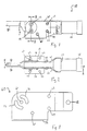
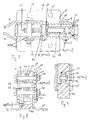
- FIG. 1-9 illustrate the enclosed pneumatic clamp 10 of the present invention, and generally comprises a pneumatic cylinder 20 removably secured to a body 40 by brackets 60, 61.
- the body 40 and brackets 60, 61 enclose a linkage means that converts the linear motion of a piston rod 22 into rotational motion of a drive ratchet 52.
- Clamp arms 80, 81 are removably attached to the drive ratchet to rotate with the drive ratchet 52 and provide the clamping force on a workpiece (not shown).
- the pneumatic cylinder 20 has a fluid chamber 24 therein and a pair of fluid ports 25,26 (fig. 4) longitudinally spaced in first and second cylinder heads 27, 28 respectively, which are in fluid communication with the fluid chamber 24.
- a piston 21 slidably held within the fluid chamber 24 is securely attached to the piston rod 22, the piston rod 22 extends longitudinally in the fluid chamber 24 through an opening (not shown) in the first cylinder head 27, as illustrated in figures 4-5.
- the piston 21 is sealingly disposed for longitudinal movement within the fluid chamber 24 between the fluid ports 25, 26 in order to selectively retract (fig. 4) and extend (fig. 5) the piston rod 22 longitudinally in response to respective greater and lesser fluid pressures in one of the fluid ports with respect to the other fluid port.
- Figures 4-5 demonstrate the body 40 includes a longitudinal bore 42 to receive the piston rod 22, and the bore 42 is in communication with a pentagonally-shaped cavity 44 open on both sides of the body 40. Longitudinal grooves 45 extend from the cavity 44 along opposite sides of the bore 42 to leave the bore 42 partially open.
- the body 40 is molded out of Delrin or other plastic such as polyurethane to reduce the weight of the clamp and to simplify the production of the body 40.
- Figure 2 illustrates the dimension of the body 40 between the brackets 60, 61 is relatively narrow further reducing the weight of the clamp. Additionally, the small coefficient of friction between Delrin and the piston rod 22 allows the piston rod 22 to easily more through the bore 42 of the body 40 without any lubrication.
- Fig. 3 illustrates one 60 of two brackets for the present invention that removably secures the body 40 to the cylinder head at a threaded opening 128 in the cylinder head 27 and substantially covers the bore 42 and cavity 44. Only a nylon washer 92 is needed, illustrated in fig. 6, to fluidly seal the body.
- the brackets 60, 61 rest on opposite sides of the body 40.
- Each bracket has a first opening 62 to receive a first fastener (not shown), such as a bolt, to attach the brackets 60, 61 to the cylinder 20; second and third openings 63, 64 to receive second and third fasteners 65, 66, such as bolts (illustrated in figs.
- each bracket has a pair of circumferentially-spaced grooves 71, 72 extending generally for 90° in opposing quadrants with the fifth opening 69 at the center of the circumferentially-spaced grooves 71, 72.
- Each circumferentially-spaced groove receives a shoulder screw 73, 74 (figs. 1-2 and 7-8) to secure the clamp arms 80, 81 to the drive ratchet 52.
- the brackets 60, 61 further include a generally perpendicular portion 75, 76, shown in figs. 2-3, with openings 77 to receive securing means (not shown), such as bolts, to secure the clamp to a work station.
- the linkage means is best illustrated in figures 4-5, and includes a linearly-shaped drive link 48, a linearly-shaped anchor link 49, each having openings at the ends, and the drive ratchet 52.
- the drive ratchet 52 is pentagonally shaped with three openings 54, 55, 56 in alignment, two openings 54, 56 are positioned in two corners of the drive ratchet 52.
- the center opening 55 is held in alignment with the fifth opening 69 of the brackets 60, 61 by the first-stepped pivot pin 70 which pivotally connects the drive ratchet 52 to the brackets.
- the two outer openings 54, 56 of the drive ratchet 52 receive the shoulder screws 73, 74 to secure the clamps arms 80, 81 to the drive ratchet 52 adjacent the outer surface of the brackets.
- the drive ratchet 52 further includes a linear slot 53 having a longitudinal axis that is perpendicular to the line established by the three openings of the drive ratchet 52 and intersecting the center opening 55.
- the slot 53 receives a second-stepped pivot pin 78 (shown in figure 7) having a central portion hexagonally shaped to provide more point-contact area with the drive ratchet 52.
- Figures 4-5 and 7-9 illustrate the pivotal cooperation between the drive ratchet 52, anchor 49 and drive links 48, and piston rod 22.
- Figure 9 demonstrates a pivot pin 90 pivotally connects and aligns first ends of two drive links 48 on opposite sides of the piston rod 22 at a first axis.
- the drive links 48 are longitudinally positioned adjacent the bore 42 in the adjacenf-grooves 45.
- the second-stepped pivot pin 78 pivotally connects and aligns first ends of two anchor links 49 on the outside of second ends of the two drive links 48 at a second axis.
- the second-stepped pivot pin 78 slidingly cooperates within the slots 53 of three aligned drive ratchets 52 effectively connecting the anchor 49 and drive links 48 to the drive ratchet 52 in pivotal cooperation at the second axis.
- the three drive ratchets 52 are aligned side by side in between the drive 48 and anchor links 49.
- the bolt 68 held in the fourth opening 67 of the brackets 60, 61 pivotally anchors the second end of the anchor link 49 to the brackets and establishes a third axis.
- the first-stepped pivot pin 70 held in the fifth opening 69 of the bracket 60, 61 pivotally anchors the drive ratchet 52 at the center opening 55 to the brackets and establishes a fourth axis.
- three drive ratchets The purpose for three drive ratchets is to have a thin enough piece of metal that can be produced using a typical stamping technique without having to machine or die cast the piece. Additionally, the brackets, clamp arms, and drive and anchor links are also produced using the same typical stamping technique to reduce manufacturing costs and time needed to produce the components.
- Figure 4 illustrates the present invention with the piston rod 22 in the retracted position where the first, second and fourth axes establish a first plane perpendicular to a second plane established by the second and third axes.
- the piston 21 experiences air pressure differentials within the fluid chamber 24 of the cylinder 20 , the piston 21 moves in the direction of the lesser fluid pressure, and in this illustration, begins to move the piston rod 22 into the extended position, as shown in figure 5, where the second and third axes establish a plane parallel to a plane established by the first and fourth axes.
- axis one is moved longitudinally through the bore 42 while the second axis rotates about the third axis and simultaneously slides through the slot 53 of the drive ratchet 52 to rotate the drive ratchet 52 in a clockwise motion.
- the grooves 71, 72 in the brackets allow the shoulder screws 73, 74 to rotate with the drive ratchet 52 to selectively move the clamp arms 80, 81 into the clamped position of figure 4, and alternatively, the released position of figure 5.
- the shoulder screws 73, 74 are precisely stacked with suitable spacers 82 and wave or spring (or curved or belleville) washers 83 to provide proper tightening force between the clamp arms and brackets while permitting free rotation of the clamp arms.
- the nylon washer 92 secured between the clamp arms 80, 81 and brackets 60, 61 includes three openings 93 in a line, the outer two openings receive the shoulder screws 73, 74 with the center opening receiving the first-stepped pivot pin 70, and with the brackets 60, 61 create a fluid-tight seal with the body 40. Accordingly, the drive link 48, anchor link 49 and drive ratchet 52 are sealed from the environment allowing lubricating fluid such as grease to be directly added and contained therein without contamination during machining operations. This feature eliminates the necessity to add a lubricating fluid through the pneumatic system which can allow impurities to enter the actuating mechanism and cause the clamp to fail.
- the clamp operates to release the clamp arms from a workpiece when the piston rod is extending through the bore using the stroke of greatest force where there has been the most frequent binding of similar clamping mechanisms due to contaminates such as chips or shavings to interfere with the motion of the clamp arms.
- clamp arms could have any configuration necessary for a particular work piece requiring at least two openings to receive the shoulder bolts 73, 74. It is understood the brackets have inverted designs to facilitate alignment on opposite sides of the body. Additionally, it is understood the clamp could be hydraulically powered.
Landscapes
- Engineering & Computer Science (AREA)
- Mechanical Engineering (AREA)
- Clamps And Clips (AREA)
- Jigs For Machine Tools (AREA)
Claims (7)
- Gekapselte fluidbetätigte Klemme mit:worin das Gehäuse einen Körper (40) mit der mit dem Hohlraum (44) in Verbindung stehenden Längsbohrung (42) und zwei Träger (60, 61) auf gegenüberliegenden Seiten des Körpers (40) einschließt, um den Körper (40) in Längsrichtung am Zylinder (20) abnehmbar zu befestigen;einem Zylinder (20), der eine Fluidkammer (24) enthält, und einem Paar in Längsrichtung voneinander beabstandeter Fluidöffnungen (25, 26) in Fluidverbindung mit der Fluidkammer (24);einem Kolben (21), der für eine gleitende Längsbewegung innerhalb der Fluidkammer (24) zwischen den Fluidöffnungen (25, 26) abdichtend angeordnet ist, um den Kolben (21) als Antwort auf höhere bzw. niedrigere Fluiddrücke in einer der Fluidöffnungen (25, 26) in Bezug auf die andere der Fluidöffnungen (25, 26) in Längsrichtung selektiv zu bewegen;einer Kolbenstange (22) mit einem am Kolben (21) abnehmbar angebrachten ersten Ende;einem am Zylinder (20) abnehmbar befestigten Gehäuse, wobei das Gehäuse eine gekapselte Längsbohrung (42), um ein zweites Ende der Kolbenstange (22) aufzunehmen, und einen mit der Bohrung (42) in Verbindung stehenden gekapselten Hohlraum (44) aufweist;einem Gestänge, das mit einem zweiten Ende der Kolbenstange (22) gelenkig verbunden ist und mit dem Gehäuse innerhalb des Hohlraums (44) gelenkig verbunden ist, wobei das Gestänge eine Längsbewegung der Kolbenstange (22) in eine Drehbewegung eines Gestängeelements umwandelt; undzumindest einem Klemmarm (80, 81), der am Gestängeelement abnehmbar befestigt ist, das zumindest einen Teil des Klemmarms (80, 81) außerhalb des Gehäuses für eine Drehbewegung des Klemmarms (80, 81) zusammenwirken läßt;
worin jeder Träger (60, 61) in Umfangsrichtung beabstandete Rillen (71, 72) aufweist; und
worin ein Befestigungsmittel den zumindest einen Klemmarm (80, 81) durch die in Umfangsrichtung beabstandeten Rillen (71, 72) in den Trägern (60, 61) am Gestängeelement abnehmbar befestigt. - Gekapselte fluidbetätigte Klemme nach Anspruch 1, worin die beiden Träger (60, 61) auf gegenüberliegenden Seiten des Körpers die Bohrung (42) und den Hohlraum (44) fluidmäßig abdichten;
das Gestänge mit den Trägern (60, 61) im Inneren des Hohlraums (44) des Körpers (40) gelenkig verbunden ist; und
der zumindest eine Klemmarm (80, 81) am Gestängeelement außerhalb der Träger (60, 61) abnehmbar befestigt ist. - Gekapselte fluidbetätigte Klemme nach Anspruch 1, worin das Gestänge ein Antriebsglied (48) mit einer ersten Gelenkverbindung mit dem zweiten Ende der Kolbenstange (22) an einer ersten Achse und einer zweiten Gelenkverbindung mit einem Ankerglied (49) an einer zweiten Achse einschließt, die Gelenkverbindung an der zweiten Achse mit einer Antriebsklinke (52) in einem geradlinigen Schlitz (53) gleitend zusammenwirkt, wobei das Ankerglied (49) eine zweite Gelenkverbindung mit dem Gehäuse an einer dritten Achse aufweist, die Antriebsklinke ferner eine Gelenkverbindung mit dem Gehäuse an einer vierten Achse aufweist, der geradlinige Schlitz (53) zur vierten Achse senkrecht ist, die Kolbenstange (22) eine zurückgezogene Stellung aufweist, bei der die erste, zweite und vierte Achse eine Ebene bilden, die zu einer durch die zweite und dritte Achse gebildeten Ebene senkrecht ist, und die Kolbenstange (22) eine ausgefahrene Stellung hat, bei der die zweite und dritte Achse eine zu einer durch die erste und vierte Achse gebildete Ebene parallele Ebene bilden.
- Gekapselte fluidbetätigte Klemme nach Anspruch 3, worin die beiden Träger die Bohrung und den Hohlraum fluidmäßig abdichten; und
der zumindest eine Klemmarm (80, 81) an der Antriebsklinke abnehmbar befestigt ist. - Gekapselte fluidbetätigte Klemme nach einem der vorhergehenden Ansprüche, worin der zumindest eine Klemmarm (80, 81) zwei, auf gegenüberliegenden Seiten des Gehäuses in Bezug auf den anderen ausgerichtete Klemmarme (80, 81) aufweist.
- Gekapselte fluidbetätigte Klemme nach einem der vorhergehenden Ansprüche, ferner enthaltend zwischen dem zumindest einen Klemmarm (80, 81) und den Trägern (60, 61) befestigte Unterlegscheiben aus Nylon, um eine fluiddichte Abdichtung an den in Umfangsrichtung beabstandeten Rillen (71, 72) der Träger (60, 61) zu schaffen.
- Gekapselte fluidbetätigte Klemme nach einem der vorhergehenden Ansprüche, worin der Kolben (21) pneumatisch angetrieben wird.
Priority Applications (2)
| Application Number | Priority Date | Filing Date | Title |
|---|---|---|---|
| EP19980301257 EP0937545B1 (de) | 1998-02-18 | 1998-02-18 | Geschlossene pneumatische Spannvorrichtung |
| DE1998605497 DE69805497T2 (de) | 1998-02-18 | 1998-02-18 | Geschlossene pneumatische Spannvorrichtung |
Applications Claiming Priority (1)
| Application Number | Priority Date | Filing Date | Title |
|---|---|---|---|
| EP19980301257 EP0937545B1 (de) | 1998-02-18 | 1998-02-18 | Geschlossene pneumatische Spannvorrichtung |
Publications (2)
| Publication Number | Publication Date |
|---|---|
| EP0937545A1 EP0937545A1 (de) | 1999-08-25 |
| EP0937545B1 true EP0937545B1 (de) | 2002-05-22 |
Family
ID=8234679
Family Applications (1)
| Application Number | Title | Priority Date | Filing Date |
|---|---|---|---|
| EP19980301257 Expired - Lifetime EP0937545B1 (de) | 1998-02-18 | 1998-02-18 | Geschlossene pneumatische Spannvorrichtung |
Country Status (2)
| Country | Link |
|---|---|
| EP (1) | EP0937545B1 (de) |
| DE (1) | DE69805497T2 (de) |
Families Citing this family (1)
| Publication number | Priority date | Publication date | Assignee | Title |
|---|---|---|---|---|
| DE102004040606B3 (de) * | 2004-08-21 | 2006-01-12 | Tünkers Maschinenbau Gmbh | Als Gripper ausgebildete Kniehebelspannvorrichtung, insbesondere zur Verwendung im Karosseriebau der Kfz-Industrie |
Family Cites Families (6)
| Publication number | Priority date | Publication date | Assignee | Title |
|---|---|---|---|---|
| US3545050A (en) * | 1969-01-30 | 1970-12-08 | I S I Mfg Inc | Power clamp with pull-back action |
| DE3419878C1 (de) * | 1984-05-28 | 1985-12-19 | De-Sta-Co Metallerzeugnisse Gmbh, 6000 Frankfurt | Tragplatte insbesondere Transportwagen- od. Palettentragplatte mit Spannvorrichtung |
| FR2588494B3 (fr) * | 1985-10-11 | 1988-01-15 | Renault Automation | Dispositif de bridage de pieces |
| DE3938208C1 (de) * | 1989-11-17 | 1990-11-22 | Josef Gerhard 4030 Ratingen De Tuenkers | |
| US5215295A (en) * | 1992-06-29 | 1993-06-01 | Delaware Capital Formation | Enclosed rotatable head power clamp |
| US5634629A (en) * | 1994-12-22 | 1997-06-03 | Isi Norgren Inc. | Rotary clamp having a common plane mounting arrangement |
-
1998
- 1998-02-18 EP EP19980301257 patent/EP0937545B1/de not_active Expired - Lifetime
- 1998-02-18 DE DE1998605497 patent/DE69805497T2/de not_active Expired - Lifetime
Also Published As
| Publication number | Publication date |
|---|---|
| DE69805497T2 (de) | 2003-01-16 |
| DE69805497D1 (de) | 2002-06-27 |
| EP0937545A1 (de) | 1999-08-25 |
Similar Documents
| Publication | Publication Date | Title |
|---|---|---|
| US5171001A (en) | Sealed power clamp | |
| US6059277A (en) | Retracting power clamp | |
| US6612557B2 (en) | Adjustable stroke clamp | |
| CA1233322A (en) | Automatic centering and gripper apparatus | |
| EP0771614B1 (de) | Angetriebene Spannvorrichtung | |
| US6908077B2 (en) | Clamp with swinging and linear motion | |
| US6666489B2 (en) | Sealed gripper apparatus | |
| US6378855B1 (en) | Locking pin clamp | |
| US6105947A (en) | Low profile pneumatic retractor clamp | |
| US5967502A (en) | Enclosed pneumatic clamp | |
| US5823519A (en) | Toggle lever clamp | |
| US20050242483A1 (en) | Pin clamp | |
| US20050225018A1 (en) | Toggle clamping device | |
| US5634629A (en) | Rotary clamp having a common plane mounting arrangement | |
| US6877730B2 (en) | Powered clamp | |
| US8029229B2 (en) | Compensator for robotic arm | |
| KR100443733B1 (ko) | 척 장치 | |
| US20050035516A1 (en) | Sealed pin locator clamp | |
| US6412845B1 (en) | Sealed gripper | |
| US7156384B1 (en) | Multi-purpose flexible jaw universal vise with removable clamp feature | |
| US20020153650A1 (en) | Powered pivot unit | |
| EP0937545A1 (de) | Geschlossene hydraulische Spannvorrichtung | |
| US4982988A (en) | Side panel clamp mechanism | |
| CN217620049U (zh) | 一种液压夹钳 | |
| EP0937538A1 (de) | Einschiebare pneumatische Flachprofilspannvorrichtung |
Legal Events
| Date | Code | Title | Description |
|---|---|---|---|
| PUAI | Public reference made under article 153(3) epc to a published international application that has entered the european phase |
Free format text: ORIGINAL CODE: 0009012 |
|
| AK | Designated contracting states |
Kind code of ref document: A1 Designated state(s): DE FR GB IT |
|
| AX | Request for extension of the european patent |
Free format text: AL;LT;LV;MK;RO;SI |
|
| 17P | Request for examination filed |
Effective date: 20000225 |
|
| AKX | Designation fees paid |
Free format text: DE FR GB IT |
|
| 17Q | First examination report despatched |
Effective date: 20001219 |
|
| GRAG | Despatch of communication of intention to grant |
Free format text: ORIGINAL CODE: EPIDOS AGRA |
|
| GRAG | Despatch of communication of intention to grant |
Free format text: ORIGINAL CODE: EPIDOS AGRA |
|
| GRAH | Despatch of communication of intention to grant a patent |
Free format text: ORIGINAL CODE: EPIDOS IGRA |
|
| GRAH | Despatch of communication of intention to grant a patent |
Free format text: ORIGINAL CODE: EPIDOS IGRA |
|
| GRAA | (expected) grant |
Free format text: ORIGINAL CODE: 0009210 |
|
| REG | Reference to a national code |
Ref country code: GB Ref legal event code: FG4D |
|
| REF | Corresponds to: |
Ref document number: 69805497 Country of ref document: DE Date of ref document: 20020627 |
|
| ET | Fr: translation filed | ||
| RAP2 | Party data changed (patent owner data changed or rights of a patent transferred) |
Owner name: DELAWARE CAPITAL FORMATION, INC. |
|
| PLBE | No opposition filed within time limit |
Free format text: ORIGINAL CODE: 0009261 |
|
| STAA | Information on the status of an ep patent application or granted ep patent |
Free format text: STATUS: NO OPPOSITION FILED WITHIN TIME LIMIT |
|
| 26N | No opposition filed |
Effective date: 20030225 |
|
| REG | Reference to a national code |
Ref country code: FR Ref legal event code: CA |
|
| PGFP | Annual fee paid to national office [announced via postgrant information from national office to epo] |
Ref country code: GB Payment date: 20040218 Year of fee payment: 7 |
|
| PG25 | Lapsed in a contracting state [announced via postgrant information from national office to epo] |
Ref country code: IT Free format text: LAPSE BECAUSE OF NON-PAYMENT OF DUE FEES;WARNING: LAPSES OF ITALIAN PATENTS WITH EFFECTIVE DATE BEFORE 2007 MAY HAVE OCCURRED AT ANY TIME BEFORE 2007. THE CORRECT EFFECTIVE DATE MAY BE DIFFERENT FROM THE ONE RECORDED. Effective date: 20050218 Ref country code: GB Free format text: LAPSE BECAUSE OF NON-PAYMENT OF DUE FEES Effective date: 20050218 |
|
| GBPC | Gb: european patent ceased through non-payment of renewal fee |
Effective date: 20050218 |
|
| REG | Reference to a national code |
Ref country code: FR Ref legal event code: ST Effective date: 20091030 |
|
| REG | Reference to a national code |
Ref country code: FR Ref legal event code: RN |
|
| PG25 | Lapsed in a contracting state [announced via postgrant information from national office to epo] |
Ref country code: FR Free format text: LAPSE BECAUSE OF NON-PAYMENT OF DUE FEES Effective date: 20090302 |
|
| REG | Reference to a national code |
Ref country code: FR Ref legal event code: D3 |
|
| PGRI | Patent reinstated in contracting state [announced from national office to epo] |
Ref country code: FR Effective date: 20100428 |
|
| PGFP | Annual fee paid to national office [announced via postgrant information from national office to epo] |
Ref country code: FR Payment date: 20120306 Year of fee payment: 15 |
|
| PGFP | Annual fee paid to national office [announced via postgrant information from national office to epo] |
Ref country code: DE Payment date: 20120228 Year of fee payment: 15 |
|
| REG | Reference to a national code |
Ref country code: FR Ref legal event code: ST Effective date: 20131031 |
|
| REG | Reference to a national code |
Ref country code: DE Ref legal event code: R119 Ref document number: 69805497 Country of ref document: DE Effective date: 20130903 |
|
| PG25 | Lapsed in a contracting state [announced via postgrant information from national office to epo] |
Ref country code: DE Free format text: LAPSE BECAUSE OF NON-PAYMENT OF DUE FEES Effective date: 20130903 Ref country code: FR Free format text: LAPSE BECAUSE OF NON-PAYMENT OF DUE FEES Effective date: 20130228 |