EP0937232B1 - Elektronische wägevorrichtung mit akustischen oberflächenwellen - Google Patents
Elektronische wägevorrichtung mit akustischen oberflächenwellen Download PDFInfo
- Publication number
- EP0937232B1 EP0937232B1 EP97939640A EP97939640A EP0937232B1 EP 0937232 B1 EP0937232 B1 EP 0937232B1 EP 97939640 A EP97939640 A EP 97939640A EP 97939640 A EP97939640 A EP 97939640A EP 0937232 B1 EP0937232 B1 EP 0937232B1
- Authority
- EP
- European Patent Office
- Prior art keywords
- amplifier
- frequency
- transducers
- substrate
- transducer
- Prior art date
- Legal status (The legal status is an assumption and is not a legal conclusion. Google has not performed a legal analysis and makes no representation as to the accuracy of the status listed.)
- Expired - Lifetime
Links
- 238000005303 weighing Methods 0.000 title claims abstract description 28
- 238000010897 surface acoustic wave method Methods 0.000 title claims description 61
- 239000000758 substrate Substances 0.000 claims abstract description 128
- 238000006073 displacement reaction Methods 0.000 claims abstract description 41
- 230000010363 phase shift Effects 0.000 claims abstract description 12
- 230000008859 change Effects 0.000 claims description 22
- 230000006870 function Effects 0.000 claims description 16
- 230000000737 periodic effect Effects 0.000 claims description 16
- 238000012545 processing Methods 0.000 claims description 8
- 239000011810 insulating material Substances 0.000 claims description 3
- 238000001514 detection method Methods 0.000 claims 2
- 230000003213 activating effect Effects 0.000 claims 1
- 238000005259 measurement Methods 0.000 abstract description 16
- 230000000694 effects Effects 0.000 abstract description 7
- 230000002277 temperature effect Effects 0.000 abstract description 4
- 230000010355 oscillation Effects 0.000 description 40
- 230000004044 response Effects 0.000 description 12
- 239000012212 insulator Substances 0.000 description 8
- 230000008901 benefit Effects 0.000 description 4
- 238000010586 diagram Methods 0.000 description 4
- 238000005516 engineering process Methods 0.000 description 4
- 230000014509 gene expression Effects 0.000 description 4
- 230000007423 decrease Effects 0.000 description 3
- 239000000463 material Substances 0.000 description 3
- 230000000295 complement effect Effects 0.000 description 2
- 239000004020 conductor Substances 0.000 description 2
- 230000005684 electric field Effects 0.000 description 2
- GQYHUHYESMUTHG-UHFFFAOYSA-N lithium niobate Chemical compound [Li+].[O-][Nb](=O)=O GQYHUHYESMUTHG-UHFFFAOYSA-N 0.000 description 2
- 238000000034 method Methods 0.000 description 2
- 230000000644 propagated effect Effects 0.000 description 2
- 238000004904 shortening Methods 0.000 description 2
- 229910000831 Steel Inorganic materials 0.000 description 1
- 230000002411 adverse Effects 0.000 description 1
- XAGFODPZIPBFFR-UHFFFAOYSA-N aluminium Chemical compound [Al] XAGFODPZIPBFFR-UHFFFAOYSA-N 0.000 description 1
- 229910052782 aluminium Inorganic materials 0.000 description 1
- 238000005452 bending Methods 0.000 description 1
- 238000009529 body temperature measurement Methods 0.000 description 1
- 238000006243 chemical reaction Methods 0.000 description 1
- 230000002301 combined effect Effects 0.000 description 1
- 230000001010 compromised effect Effects 0.000 description 1
- 238000011109 contamination Methods 0.000 description 1
- 238000012937 correction Methods 0.000 description 1
- 239000007788 liquid Substances 0.000 description 1
- 238000012544 monitoring process Methods 0.000 description 1
- 230000001902 propagating effect Effects 0.000 description 1
- 230000000284 resting effect Effects 0.000 description 1
- 238000005488 sandblasting Methods 0.000 description 1
- 238000007789 sealing Methods 0.000 description 1
- 230000035945 sensitivity Effects 0.000 description 1
- 239000010959 steel Substances 0.000 description 1
Images


Classifications
-
- G—PHYSICS
- G01—MEASURING; TESTING
- G01G—WEIGHING
- G01G3/00—Weighing apparatus characterised by the use of elastically-deformable members, e.g. spring balances
- G01G3/12—Weighing apparatus characterised by the use of elastically-deformable members, e.g. spring balances wherein the weighing element is in the form of a solid body stressed by pressure or tension during weighing
- G01G3/13—Weighing apparatus characterised by the use of elastically-deformable members, e.g. spring balances wherein the weighing element is in the form of a solid body stressed by pressure or tension during weighing having piezoelectric or piezoresistive properties
Definitions
- the invention relates to electronic weighing devices. More particularly, the invention relates to an electronic weighing device which employs surface acoustic waves to measure weight.
- Precision electronic weighing devices are widely known in the art and there are many different technologies utilized in these electronic weighing devices.
- Laboratory scales or "balances" typically have a capacity of about 1,200 grams and a resolution of about 0.1 gram, although scales with the same resolution and a range of 12,000 grams are available.
- the accuracy of these scales is achieved through the use of a technology known as magnetic force restoration.
- magnetic force restoration involves the use of an electromagnet to oppose the weight on the scale platform. The greater the weight on the platform, the greater the electrical current needed to maintain the weight. While these scales are very accurate (up to one part in 120,000), they are expensive and very sensitive to ambient temperature. In addition, their range is relatively limited.
- load cell scales Most all other electronic weighing devices use load cell technology.
- the applied weight compresses a column which has strain gauges bonded to its surface.
- the strain gauge is a fine wire which undergoes a change in electrical resistance when it is either stretched or compressed. A measurement of this change in resistance yields a measure of the applied weight.
- Load cell scales are used in non-critical weighing operations and usually have a resolution of about one part in 3,000. The maximum resolution available in a load cell scale is about one part in 10,000 which is insufficient for many critical weighing operations. However, load cell scales can have a capacity of several thousand pounds.
- US-A-4,107,626 and US-A-4,623,813 disclose electronic weighing apparatus having a SAW transmitter and a SAW receiver mounted on the surface of a member which deflects according to an applied load, the transmitter and receiver being interconnected with an amplifier to form an oscillator.
- US-A-5,476,002 discloses a contamination monitor which includes SAW transducers mounted to a heat sink.
- an electronic weighing apparatus comprising:
- the electronic weighing apparatus of the present invention includes a base which supports a cantilevered elastic member upon which a load platform is mounted.
- the free end of the elastic member is provided with a first piezoelectric transducer and a second piezoelectric transducer is supported by the base.
- the interior of the elastic member is hollowed and is provided with first and second piezoelectric transducers which are mounted on respective opposed posts.
- each transducer includes a substantially rectangular piezoelectric substrate and a pair of electrodes acting as a transmitter and the other pair of electrodes acting as a receiver.
- the transducers are arranged with their substrates substantially parallel to each other with a small gap between them and with their respective electrodes in relatively opposite positions.
- the receiver electrodes of the second transducer are coupled to the input of an amplifier and the output of the amplifier is coupled to the transmitter electrodes of the first transducer.
- the transducers form a "delay line” and the resulting circuit of the delay line and the amplifier is a positive feedback loop, i.e. a natural oscillator. More particularly, the output of the amplifier causes the first transducer to emit a surface acoustic wave (“SAW”) which propagates along the surface of the first transducer substrate away from its electrodes.
- SAW surface acoustic wave
- the propagating waves in the first transducer induce an oscillating electric field in the substrate which in turn induces similar SAW waves on the surface of the second transducer substrate which propagate in the same direction along the surface of the second transducer substrate toward the electrodes of the second transducer.
- the induced waves in the second transducer cause it to produce an alternating voltage which is supplied by the electrodes of the second transducer to the amplifier input.
- the circuit acts as a natural oscillator, with the output of the amplifier having a particular frequency which depends on the physical characteristics of the transducers and their distance from each other, as well as the distance between the respective electrodes of the transducers.
- the cantilevered elastic member moves or bends and causes the first transducer to move relative to the second transducer.
- the movement of the first transducer relative to the second transducer causes a change in the frequency at the output of the amplifier.
- the movement or bending of the elastic member is proportional to the weight of the applied load and the frequency and/or change in frequency at the output of the amplifier can be calibrated to the displacement of the elastic member.
- the embodiments provide for: accounting for different modes of oscillation of the frequency response of the delay line, and accounting for temperature gradients in the system.
- the provided apparatus can achieve an accuracy on the order of at least one part in one hundred thousand, e.g. one gram per hundred kilograms.
- the components of the apparatus are easily manufactured and the assembly of the apparatus is inexpensive.
- the circuit which is coupled to the outputs of the amplifiers may be provided with self-calibration capability and can be provided with a user-friendly interface so that the apparatus is easy to use. Additional objects and advantages of the invention will become apparent to those skilled in the art upon reference to the detailed description taken in conjunction with the provided figures.
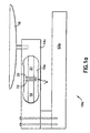
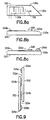
- a first embodiment of an electronic weighing apparatus 10 includes a base 12 which supports a cantilevered elastic member 14 having a cut-out 15, and upon which a load platform 16 is mounted.
- the free end 18 of the elastic member is provided with a first piezoelectric transducer 20 and a second piezoelectric transducer 22 is supported by the base 12.
- the elastic member 14 is provided with a strain gauge 17 or other means of determining gross position.
- FIG. 1a A second, presently preferred embodiment of an electronic weighing apparatus 10a according to the invention is seen in Figure 1a to include a base 12a which supports a cantilevered elastic member 14a having a cut-out 15a, and upon which a load platform 16 is mounted.
- the cut-out 15a is provided with two opposed posts 19, 21 upon which are respectively mounted a first piezoelectric transducer 20 and a second piezoelectric transducer 22.
- the posts 19, 21 serve to locate the transducers 20, 22 at the center of the elastic member 14a and to mechanically couple the transducers to opposite ends of the elastic member 14a. It will be appreciated that locating the transducers at the center of the elastic member compensates for any torque on the member which would exhibit itself at the free end of the member.
- the elastic member is made of aluminum or steel.
- the presently preferred elastic member exhibits a maximum displacement of 0.1 to 0.2 mm at maximum load.
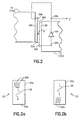
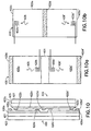
- the first transducer 20 includes a substantially rectangular piezoelectric substrate 20a and a pair of electrodes 20b imprinted on the substrate at the upper end thereof.
- the second transducer 22 includes a substantially rectangular piezoelectric substrate 22a and a pair of electrodes 22b imprinted on the substrate at the lower end thereof.
- the substrates are preferably made of lithium-niobate.
- the transducers are arranged with their substrates substantially parallel to each other with a small gap "g" between them.
- the electrodes 22b of the second transducer 22 are coupled to the input 24a of an amplifier 24 powered by a power source (not shown) and the output 24b of the amplifier 24 is coupled to the electrodes 20b of the first transducer 20.
- the resulting circuit is a positive feedback loop natural oscillator, a "delay line”.
- the output 24b of the amplifier 24 generates an alternating voltage in the electrodes 20b of the first transducer 20 which generates a surface acoustic wave (“SAW”) 26 which propagates along the surface of the first transducer substrate 20a away from its electrodes 20b.
- SAW surface acoustic wave
- an oscillating electric field which is induced as a result of the SAW waves 26 in the piezoelectric substrate 20a is able to in turn induce similar SAW waves 28 on the surface of the second transducer substrate 22a which propagate in the same direction along the surface of the second transducer substrate toward the electrodes 22b of the second transducer 22.
- the induced waves 28 in the second transducer 22 cause the electrode 22b of the second transducer 22 to produce an alternating voltage which is provided to the input 24a of the amplifier 24.
- the circuit acts as a natural oscillator with the output 24a of the amplifier 24 having a particular frequency which depends on the physical characteristics of the transducers and their distance from each other, as well as the distance between the respective electrodes of the transducers.
- the frequency of the oscillator is directly related to the time it takes for the SAW to propagate from the electrodes 20b to the electrodes 22b.
- the SAW 26 has a wavelength of approximately 100-200 microns at 20-50 MHz.
- the gap "g" between the substrates of the first and second transducers is as small as possible and preferably no more than one half to one wavelength, i.e. 100-200 microns; and even more preferably, no more than 0.1 wavelength. With such a gap, an oscillating system can typically be generated if the amplifier 24 has a gain of at least approximately 17 dB.
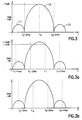
- the frequency response of the delay line is represented by a series of lobes, e.g. L1, L2, and L3 which represent possible frequencies of oscillation of the oscillator circuit, i.e. where the gain is greater than the loss.
- the central or main lobe L2 includes the frequencies at which the oscillator has the lowest loss.
- the frequency f 0 is the frequency in the main lobe L2 where the circuit has the minimum loss. Since the frequency response curve is divided into these lobes, it will be understood that there are some frequencies at which the circuit will not oscillate. Moreover, it will be appreciated that the circuit will attempt to oscillate at the frequency having the least loss and that the frequency of oscillation may change modes to achieve the lowest loss.
- the different modes of oscillation are frequencies which have a phase shift of multiples of 2 ⁇ .
- three modes of oscillation, f 0 , f 0 +2 ⁇ and f 0 -2 ⁇ , are shown in Figure 3, where w is a constant. Since the loss in frequency response among these modes is the lowest at the frequency f 0 , the oscillator will oscillate at f 0 .
- the frequency of the oscillator increases.
- the frequency of the oscillator will rise from f 0 ( Figure 3) to f 1 ( Figure 3a).
- the frequency response of the delay line exhibits many modes of oscillation, four of which, f 1 , f 1 +2 ⁇ , f 1 -2 ⁇ , and f 1 -4 ⁇ , are shown in Figure 3a.
- f 1 is the frequency of the mode with the lowest loss; but the loss at the mode having the frequency f 1 -2 ⁇ is almost as low as the mode having the frequency f 1.
- the frequency of the oscillator will increase beyond the frequency f 1 to a frequency f 2 +2 ⁇ shown in Figure 3b.
- Figure 3b it will be appreciated that when the frequency of the oscillator is brought to f 2 +2 ⁇ , many nodes of oscillation are possible, including: f 2 , f 2 +2 ⁇ , f 2 -2 ⁇ , and f 2 +4 ⁇ . It will also be appreciated from Figure 3b that the loss in response at the mode having the frequency f 2 is less than the loss at the mode having the frequency f 2 +2 ⁇ . The oscillator will therefore change modes of oscillation and oscillate at a lower frequency, i.e. f 2 .
- the changing of the modes of oscillation can be avoided by limiting the displacement of the first transducer so that the frequency of the oscillator is never brought beyond the frequency at which the mode of oscillation would change.
- the delay line By designing the delay line to exhibit an appropriate frequency response, it is possible to allow the length of the delay line to change by up to one wavelength before the mode of oscillation changes.
- the length of the delay line could be shortened by about 200 microns, i.e. the elastic member could be displaced by about 200 microns without causing a change in the mode of oscillation. Such a small displacement would either limit the range of weight measurement or would reduce the "resolution" (accuracy) of the measurement depending on the characteristics of the elastic member.
- a "soft" elastic member could be used for measuring a small range of light weights
- a "stiff" elastic member could be used for measuring a broad range of weights with limited accuracy.
- the length of the delay line is permitted to change by about 700 microns and the mode of oscillation is therefore permitted to change three to four times.
- Figure 4 illustrates the frequency "f" of the output of the amplifier 24 as a function of displacement "d" of the elastic member 14.
- the frequency of the amplifier output increases from a first frequency f 0 to a second frequency f 1 .
- the oscillator changes mode of oscillation and oscillates at a lower frequency f 2 rather than the higher frequency f 2 +2 ⁇ .
- the range of frequencies will repeat through f 1 at position P 3 until the mode changes again, etc.
- the frequency output of the amplifier will be a periodic function with the same frequencies generated at different displacements of the elastic member.
- the same frequency f 1 will be representative of different displacement positions P 1 , P 3 , and P 4 of the elastic member 14.
- the elastic member 14 can be provided with a gross displacement detector 17 such as a strain gauge, a capacitance or inductance transducer, or the like which generates a non-periodic output.
- Figure 4a illustrates the alternative method wherein a strain gauge or other "gross" position transducer is coupled to the elastic member to provide a non-periodic signal f' in response to the displacement of the elastic member.
- the signal f' need not represent a very accurate indication of the position of the elastic member. It is sufficient that the signal f' be accurate enough to determine how many cycles of the periodic function f' have been traversed.
- FIGs 4 and 4a when the elastic member is displaced to positions P 1, P 3 or P 4 , three distinct signals f' 1 , f' 3 , and f' 4 are generated by the gross position transducer. Each cycle of the periodic signal f is represented by a range of signals f'.
- a second periodic function f is generated and combined with or compared to the periodic function f as described in detail below.
- a second pair of transducers 80, 82 are provided adjacent to the first pair 20,22 and coupled to each other in the same type of delay line feedback loop via a second amplifier 84.
- the second pair of transducers generate and detect a SAW 86, 88 having a longer wavelength, e.g. 220 microns at 18 MHz, than the SAW 26, 28 utilized by the first pair of transducers. Therefore, the output 84b of the second amplifier 84 is a periodic function with a different frequency than the periodic function which is the output of the first amplifier 24.
- Figure 4b illustrates the periodic function f" of the output of the second amplifier 84. Comparing Figures 4 and 4b, it will be appreciated that for each position, e.g. P 1 , P 3 and P 4 , where the output of the first amplifier is the same value f 1 , the output of the second amplifier will be a non-repeating value, i.e. f" 1 , f" 3 , and f" 4 .
- the exact displacement of the elastic member may be determined, i.e., the weight of the applied load can be determined using a look-up table for a particular elastic member.
- the transducers 20 and 80 share the same substrate and generate respective SAWs in separate channels in the substrate.
- the transducers 22 and 82 share the same substrate and receive SAWs in respective substrate channels.
- One preferred frequency of the first SAW wave is 20-22 MHz and a preferred frequency of the second SAW wave is 18-20 MHz.
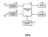
- FIG. 6 is a block diagram illustrating how the signals from the two amplifiers 24, 84 are used to indicate the weight of an object placed on the load platform.
- a first frequency counter 30 determines the frequency at the output 24b of the first amplifier and a second frequency counter 30a determines the frequency at the output 84b of the second amplifier.
- the frequency information is supplied to a processing unit 32 which is coupled to a non-volatile memory 34 which stores a look-up table.
- the frequency information is compared to the look-up table which returns a weight value and the processing unit displays that value on the display 36.
- the operation of the processing unit 32 may be controlled by a keyboard 38 which can also be used to calibrate the look-up table.
- the look-up table is typically calibrated by placing known weights on the load platform and entering the weight value(s) via the keyboard 38.
- the processing unit stores the weight values obtained from the keyboard with the frequency values obtained from the frequency counters in the form of a look-up table in the memory 34. Frequency values and corresponding weight values which are not stored in the look-up table are obtained by interpolating the values in the look-up table.
- the processing unit may include other functions for temperature compensation, compensation for non-linearity of the transducers/elastic member, conversion to different weight measurement units, etc.
- the display may be numeric, alpha-numeric, or graphical.
- a single frequency counter may be used to determine the two frequencies consecutively rather than simultaneously, in which case, the processing unit will have means for switching between the amplifiers to obtain their frequencies separately.
- the look-up table may comprise one or several look-up tables.
- an embodiment of the weighing apparatus 10 may include a circular base 12 with four radially cantilevered elastic members 14a-14d supporting the load platform 16. Each elastic member will be provided with its own transducer circuit and the weights measured at each elastic member will be summed to obtain the correct weight of a load placed on the load platform. It will be understood that more than four or fewer than four elastic members may be used to obtain similar results.
- reflected waves may occur on the substrate of the transmitting transducer which interfere with SAW wave generation and result in non-linearity of measurements. More particularly, when the wave 26 (Fig. 2a) propagates along the substrate 20a, it reaches the end 20c of the substrate and a portion of the wave is reflected back 180° toward the electrodes 20b. The reflected wave interferes with the propagated wave 26. In fact, a portion of the reflected wave is again reflected off the other end 20d of the substrate 20a causing additional interference. Reflected waves can also be a problem in the receiving transducer.
- Figures 8a-8c show several anti-reflection structures according to the invention.
- a transducer 120 includes a piezoelectric substrate 120a and a pair of electrodes 120b for generating a SAW wave 126.
- the end 120c of the substrate 120a is cut at an angle relative to the propagation path of the SAW wave 126.
- any reflection of the wave is at an angle relative to the line of propagation so that the reflected wave does not interfere with the propagated wave.
- a transducer 220 includes a piezoelectric substrate 220a and a pair of electrodes 220b for generating a SAW wave 226.
- the end 220c of the substrate 220a is rounded (e.g., by sandblasting) relative to the propagation path of the SAW wave 226.
- the wave 226 reaches the end 220c of the substrate it is scattered rather than reflected back.
- a transducer 320 includes a piezoelectric substrate 320a and a pair of electrodes 320b for generating a SAW wave 326.
- a damper such as a soft elastomeric 320d is placed on the surface of the substrate adjacent the end 320c.
- the damper material shown in Figure 8c appears to be the presently preferred structure. Accordingly, as shown in Figure 9, a pair of transducers 320, 322 are provided with damper material 320d, 322d adjacent ends 320c, 322c opposite electrodes 320b, 322b on the respective substrates 320a, 322a.
- the transducers 320, 322 are advantageously arranged in an overlapping manner as shown in Figure 9.
- the full scale output for one mode is about 200Khz. Since the substrate shows a temperature effect of 1.4Khz per degree C, this results in a 0.7% variation of the full scale per degree C. In order to maintain an accuracy of within 0.007% of the full scale, therefore, the temperature difference should be less than 0.01 degree C.
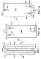
- FIGS 10, 10a, and 10b show a pair of transducers 420, 422 according to the invention which embody several aspects of the invention.
- the transducer system includes a transmitting transducer 420 and a receiving transducer 422.
- the transmitting transducer 420 includes two piezoelectric substrates 420a, 420a' which are mounted on one side a thermal sink 421, and a thermal insulator 423 is mounted on the other side of the thermal sink 421.
- the thermal sink 421 helps to maintain a constant temperature across both substrates 420a, 420a' and the thermal insulator 423 helps to prevent ambient temperature changes from affecting the temperature of the thermal sink 421 and thus the substrates 420a, 420a'.
- Each substrate 420a, 420a' has a pair of electrodes 420b, 420b' at one end thereof and a surface damper 420d, 420d' at the other end thereof.
- the substrates are arranged on the thermal sink so that their respective electrode pairs are close to each other and adjacent to the center of the transducer as seen best in Figures 6 and 7.
- the transmitting transducer 420 therefore generates two SAW waves 426, 426' which propagate in opposite directions from the approximate center of the transducer 420.
- the dampers 420d, 420d' serve to inhibit reflections of the SAW waves 426, 426'.
- the receiving transducer 422 includes a piezoelectric substrate 422a which is mounted on one side of a thermal sink 425, and a thermal insulator 427 is mounted on the other side of the thermal sink 425.
- the thermal sink 425 helps to maintain a constant temperature across the substrate 422a and the thermal insulator 427 helps to prevent ambient temperature changes from affecting the temperature of the thermal sink 425 and thus the substrate 422a.
- the substrate 422a has two pairs of electrodes 422b, 422b', each pair being located approximately at opposite rounded ends 422c, 422c' of the substrate 422a, and a surface damper 422d is located approximately at the center of the substrate 422a.
- the receiving transducer 422 therefore receives two SAW waves 428, 428' which are induced respectively by the transmitted SAW waves 426, 426', and which propagate in opposite directions.
- the electrode pairs 420b and 422b are coupled to one amplifier to form one delay line oscillator and the electrode pairs 420b' and 422b' are coupled to a second amplifier to form a second delay line oscillator.
- the combined change in frequency ⁇ f due to temperature and displacement therefore equals f 0 (k ⁇ t ⁇ g ⁇ x).
- the differential transducer system described above not only eliminates the affects of ambient temperature change from the weighing measurement, but also provides double the resolution scale of a single transducer system. Nevertheless, the system described with reference to Figures 10, 10a, and 10b will not automatically compensate for temperature gradients across the substrates of the transducer and that is why the transducer system is provided with the thermal sinks described above. It will also be appreciated that the overall length (height) of the transducer system is substantially doubled as compared with the non-differential system. In order to reduce the overall size of the transducer system and to increase the sensitivity and resolution of the system, the present invention preferably uses a frequency of approximately 50mhz as compared to the 20mhz frequency of the parent application. At this frequency, in order to achieve the desired accuracy (0.5grams per 10kg), the temperature difference between the substrates must be kept below .01 degrees C°.
- FIGS 11, 11a, and 11b show a schematic illustration of a differential transducer system similar to the one described above, but with both transducer channels operating on the same substrate and with one of the transducer channels being split.
- the transducer system includes a transmitting transducer 520 and a receiving transducer 522.
- the transmitting transducer 520 includes a piezoelectric substrate 520a which is mounted on one side a thermal sink 521, and a thermal insulator 523 is mounted on the other side of the thermal sink 521.
- the thermal sink 521 helps to maintain a constant temperature across the substrate 520a and the thermal insulator 523 helps to prevent ambient temperature changes from affecting the temperature of the thermal sink 521 and thus the substrate 520a.
- a first transmitting electrode 520b is located at one end of the substrate 520a on a central axis thereof.
- a second transmitting electrode pair 520c, 520d is located at the other end of the substrate on opposite sides of the central axis.
- Each of the electrodes 520c, 520d is approximately half the wavelength of the electrode 520b and the electrodes 520c, 520d are coupled in parallel to form the electrode pair.
- the transmitting transducer 520 therefore generates three SAW waves 526, 526', and 526".
- the first SAW wave 526 propagates along a central channel on the substrate and in a first direction.
- the second and third SAW waves 526' and 526" propagate along two side channels on the substrate an in a direction opposite to the first SAW wave.
- the receiving transducer 522 includes a piezoelectric substrate 522a which is mounted on one side of a thermal sink 525, and a thermal insulator 527 is mounted on the other side of the thermal sink 525.
- the thermal sink 525 helps to maintain a constant temperature across the substrate 522a and the thermal insulator 527 helps to prevent ambient temperature changes from affecting the temperature of the thermal sink 525 and thus the substrate 522a.
- the substrate 522a has a first receiving electrode 522b and a second receiving electrode pair 522c, 522d.
- the receiving electrode 522b is at one end of the substrate on a central axis thereof and the receiving electrodes 522c, 522d are located at the other end of the substrate on opposite sides of the central axis.
- the receiving electrodes 522c, 522d are half the wavelength of the electrode 522b and are coupled in parallel to each other.
- the receiving transducer 522 therefore receives three SAW waves 528, 528', and 528" which are induced respectively by the transmitted SAW waves 526, 526', 526".
- the arrangement shown in Figures 11, 11a, and 11b has several advantages.
- the SAW wave propagation channels are closer together on the same substrate and therefore the temperature gradient between them will be smaller.
- the overall size of the transducer system is smaller.
- the transducers are axially symmetrical which enhances mechanical performance.
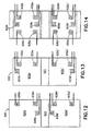
- a transmitting transducer 620 includes a first piezoelectric substrate 620a and a second piezoelectric substrate 620a', both of which are mounted on a base 623 which is preferably constructed as a sandwich of insulating and conductive materials as described above with reference to Figure 6.
- the first piezoelectric substrate 620a is provided with a first pair of transmitting electrodes 620b at a lower central portion thereof and the second piezoelectric substrate 620a' is provided with a second pair of transmitting electrodes 620b' at an upper central portion thereof.
- first piezoelectric substrate 620a is provided with two pair of electrodes 630a, 630b which are spaced apart from each other and arranged off center from the first pair of transmitting electrodes 620b.
- the electrodes 630a, 630b are respectively a transmitter and receiver which are used to measure the temperature of the substrate 620a as described below.
- the substrate 620a' is also provided with two pair of temperature measuring electrodes 630a', 630b'.
- a receiving transducer 622 includes a first piezoelectric substrate 622a and a second piezoelectric substrate 622a', both of which are mounted on a base 627 which is preferably constructed as a sandwich of insulating and conductive materials as described above with reference to Figure 6.
- the first piezoelectric substrate 622a is provided with a first pair of receiving electrodes 622b at an upper central portion thereof and the second piezoelectric substrate 622a' is provided with a second pair of transmitting electrodes 622b' at a lower central portion thereof.
- the first piezoelectric substrate 622a is provided with two pair of temperature measuring electrodes 632a, 632b which are spaced apart from each other and arranged off center from the first pair of transmitting electrodes 522b.
- the substrate 522a' is also provided with two pair of temperature measuring electrodes 632a', 632b'.
- the transducer arrangement shown in Figures 12-14 incorporates several of the features of the transducer arrangement described above with reference to Figures 10, 10a, and 10b.
- the electrode pairs 620b, 620b', 622b, 622b' are arranged to provide a differential displacement measurement system as described above.
- the differential system utilizes two acoustic channels which are centrally located, one on the upper pair of substrates and the other on the lower pair of substrates.
- the transmitting substrates are slightly larger than the receiving substrates and therefore overlap the receiving substrates with the same advantages as described above.
- the transmitting transducer 620 is approximately 45mm long and the space between the first and second substrates is approximately 5 ⁇ m.
- the receiving transducer 622 is approximately 10mm shorter than the transmitting transducer and the space between the first and second receiving substrates is approximately 5 ⁇ m.
- each of the four piezoelectric substrates is provided with a two pair of temperature measuring electrodes which are arranged as a fixed position delay line on each substrate.
- Each of the four sets of temperature measuring electrodes is coupled to a respective amplifier and thereby forms a natural oscillator which preferably oscillates at a frequency which is different from the frequency at which the displacement measuring oscillators oscillate. Since the temperature measuring electrode sets are stationary on their respective substrates, the frequency of their respective oscillators will vary only due to changes in temperature. With this provided arrangement, the temperature of each of the four substrates can be determined and accounted for when making displacement and weight measurements.
- each of the two measuring electrode sets operates in a separate acoustic channel. It is possible, however, to provide two measuring electrode sets which operate in almost the same channel. This minimizes the thermal gradient between the two channels.
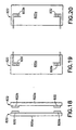
- Figures 15-17 illustrate one embodiment of such an arrangement.
- a transmitting transducer 720 includes a piezoelectric substrate 720a with a pair of transmitting electrodes 720b located at a lower end thereof and a pair of receiving electrodes 730 located at an upper end thereof.
- a receiving transducer 722 includes a piezoelectric substrate 722a with a pair of receiving electrodes 722b at an upper end thereof.
- the transmitting and receiving electrodes 720b, 722b are arranged with amplifier 750 to form a delay line for measuring displacement and weight as described above.
- the receiving electrodes 730 on the transmitting substrate form a stationary delay line with amplifier 760 and the transmitting electrodes 720b for measuring the temperature of the transmitting substrate 720a.
- the amplifiers 750 and 760 may be operated simultaneously if the delay lines have significantly different frequencies. Alternatively, the amplifiers 750, 760 may be switched on and off alternatingly. It will be appreciated that all of the electrodes operate in the same acoustic channel.
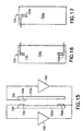
- the transducer system shown in Figures 15-17 is a non-differential system wherein the temperature of the transmitting substrate is assumed to be close to that of the receiving substrate. However, it is possible to apply the technology of this system to a differential system wherein separate measurements are made for the two channels. Such a system is shown in Figures 18-20.
- a transmitting transducer 820 includes a piezoelectric substrate 820a with a pair of transmitting electrodes 820b located at a lower end thereof and a pair of transceiving electrodes 830 located at an upper end thereof.
- a receiving transducer 822 includes a piezoelectric substrate 822a with a pair of receiving electrodes 822b at an upper end thereof and a pair of transceiving electrodes 832 at a lower end thereof. It will be appreciated that the transmitting and receiving electrodes 820b, 822b are arranged to form a delay line for measuring displacement and weight as described above.
- the transceiving electrodes 830 and 832 can be used to form a stationary delay line with respective electrodes 820b, 822b or may be used with each other to form a displacement measuring delay line which is differential to the delay line formed by electrodes 820b, 822b.
- the four electrode pairs may be multiplexed such that at one moment, two differential displacement measuring delay lines are activated and at another moment two stationary temperature measuring delay lines are activated. In this manner, the temperature of each substrate can be ascertained prior to or even during temperature measurement. It will be appreciated that all of the electrodes operate in the same acoustic channel.
- the delay lines according to the invention may oscillate in more than one mode and within each mode, the gain will vary as the frequency changes.
- the phase of the oscillator may be shifted ⁇ 180° in order to increase gain (decrease loss).
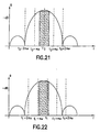
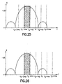
- Figures 21-26 illustrate how the modes of oscillation change during weighing and how phase shifting can be used to increase gain.
- the delay line in the idle state, with no weight applied to the scale, the delay line will oscillate at a frequency "f 0 " which is shown in Figure 21 as the point having the most gain (least loss).
- the optimal gain area of the graph of Figure 21 is shown in the shaded area surrounding f 0 and represents a range of ⁇ 100 Khz, for example. This area is considered optimal not only because it is the area of least loss, but because it is the area wherein the curve exhibits the least "non-linearity" and is least influenced by temperature.
- the delay line may oscillate in any of several modes and the modes are separated from each other by a phase difference of 2 ⁇ .
- the frequency f 0 has a lower mode f 0 -2 ⁇ and a higher mode f 0 +2 ⁇ , where w is the interger one, the phase difference between the modes representing approximately 340Khz in this example.
- the delay line will oscillate at a higher frequency "f 0 +n". For example, after adding a relatively small weight, the frequency of oscillation will rise to f 0 +70Khz which is shown in Figure 22 as f 1 .
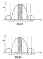
- an oscillation frequency f 2 which is approximately 120Khz higher than f 0, would move the frequency out of the optimal gain area. Nevertheless, as shown in Figure 23, the higher and lower modes of oscillation would still show greater loss than the central mode at f 2 . Those skilled in the art will therefore appreciate that from this point onward, additional weight will raise the frequency of oscillation though an increasingly high loss area until the lower mode achieves greater gain than the central mode which is shown in Figure 24.
- an oscillation frequency f 3 which is approximately 170Khz higher than f 0 would cause a shift to the lower mode of oscillation f 3 -2 ⁇ . It will be appreciated, however, that even after the mode shift, the frequency of oscillation must shift through approximately 70Khz more before oscillation of the lower mode will occur in the optimal gain area. According to the invention, therefore, it is possible to apply a phase shift of ⁇ w to the oscillator in order to force early oscillation in the optimal gain area. For example, as shown in Figures 23 and 24 as soon as the oscillation frequency f 2 exhibits loss which indicates it is no longer in the optimal gain area, a phase shift of - ⁇ is applied.
- FIG. 27 shows a simplified schematic diagram of a positive feedback loop with phase shifting according to the invention.
- a simplified delay loop according to the invention includes a first transducer 920, a second transducer 922, a first differential amplifier 950, a second differential amplifier 952, a pair of matching transformers 954,956, a frequency counter and amplifier controller 958, and an output processor and weight display 960.
- the first transducer 920 includes a piezoelectric substrate 920a and electrodes 920b.
- the second transducer 922 includes a piezoelectric substrate 922a and electrodes 922b.
- the electrodes 920b are coupled via the matching transformer 954 to the inputs of the differential amplifiers 950, 952 in a parallel manner.
- the electrodes 922b are coupled to the outputs of the amplifiers 950, 952 via the matching transformer 956. As shown in Figure 27, the polarity of the outputs of the amplifier 950 is opposite to the polarity of the outputs of the amplifier 952.
- the enable input of each amplifier is coupled to the frequency counter and amplifier controller 958 which is also coupled to the outputs of the amplifiers. According to the invention, the amplifiers 950, 952 are turned on at one time by the frequency counter and amplifier controller 958. It will be appreciated that the phase of the outputs of the amplifiers differs by 180° or ⁇ . Thus, in order to apply or remove a phase shift, one of the amplifiers is turned off and the other is turned on.
- the frequency counter and amplifier controller 958 monitors the output of the amplifier 950 and detects when the frequency passes beyond the optimal gain area as described above, e.g., increases by 100Khz. When the frequency increases by a preselected amount, the frequency counter and amplifier controller 958 turns off amplifier 950 and turns on amplifier 952. The frequency counter and amplifier controller 958 then monitors the output of amplifier 952. After the frequency increases by an additional preselected amount, e.g. 100Khz, the frequency counter and amplifier controller 958 turns off amplifier 952 and turns on amplifier 950. While the frequency counter and amplifier controller 958 is monitoring frequencies, the frequencies are passed to the output processor and weight display 960 which analyzes the frequency of oscillation, correlates the frequency with a particular weight according to the methods described in the parent application, and displays the weight.
- the frequencies are passed to the output processor and weight display 960 which analyzes the frequency of oscillation, correlates the frequency with a particular weight according to the methods described in the parent application, and displays the weight.
- the gap may be filled with a liquid or other material which allows free movement between the substrates but which decreases the loss in the oscillator loop.
- the transducers can be protected against moisture by proper sealing. A dessicant can be introduced into the sealed cavity to reduce humidity fluctuations.
- an open loop system could be utilized with a pulse generator, where the delay in, eg., an RF pulse can be measured and will be proportional to the displacement between the transducers.
- an external oscillator could be utilized, and as the transducers move relative to each other as a result of a load, a phase shift which is proportional to the displacement will occur.
Landscapes
- Physics & Mathematics (AREA)
- General Physics & Mathematics (AREA)
- Transmission And Conversion Of Sensor Element Output (AREA)
- Measurement Of Velocity Or Position Using Acoustic Or Ultrasonic Waves (AREA)
- Measurement Of Mechanical Vibrations Or Ultrasonic Waves (AREA)
- Apparatuses For Generation Of Mechanical Vibrations (AREA)
Claims (16)
- Elektrische Wiegevorrichtung, die aufweist:wobei die Vorrichtung dadurch gekennzeichnet ist, daß wenigstens einer der ersten und zweiten piezoelektrischen Meßwandler (20, 22) ein Substrat aufweist, das mit einer Anti-Reflexionsstruktur versehen ist, um Reflexion der akustischen Wellen zu minimalisieren, wobei die Anti-Reflexionsstruktur aus einem Oberflächendämpfer (320d) auf dem Substrat, einem gewinkelten Schnitt (120c) an einem Ende des Substrats oder einem abgerundeten Ende (220c) auf dem Substrat besteht.a) verschiebbare elastische Gliedmittel (14) zum Aufnehmen einer Last, und die durch die Last so verschoben werden, daß die Verschiebung der elastischen Gliedmittel zum Gewicht der Last in Bezug steht;b) einen ersten piezoelektrischen Meßwandler (20), der einen ersten Sender (20b) für akustische Oberflächenwellen (SAW) hat;c) einen zweiten piezoelektrischen Meßwandler (22), der einen ersten SAW-Empfänger (22b) aufweist, wobei der zweite piezoelektrische Meßwandler in großer Nähe zu dem ersten piezoelektrischen Meßwandler angebracht ist, wobei wenigstens einer der ersten und zweiten piezoelektrischen Meßwandler mit den elastischen Gliedmitteln (14) verbunden ist;d) einen ersten Verstärker (24) mit einem Eingang und einem Ausgang, wobei der Eingang des ersten Verstärkers mit dem ersten SAW-Empfänger (22b) verbunden ist und der Ausgang des ersten Verstärkers mit dem ersten SAW-Sender (20b) so verbunden ist, daß der erste piezoelektrische Meßwandler (20), der erste Verstärker (24) und der zweite piezoelektrische Meßwandler (22) einen ersten Oszillator bilden, der eine erste Ausgangsfrequenz hat; unde) Prozessormittel (32), die mit dem Ausgang des ersten Verstärkers verbunden sind, wobei Verschiebung der elastischen Gliedmittel (14) eine Verschiebung von einem der ersten und zweiten piezoelektrischen Meßwandler (20, 22) relativ zum anderen bewirkt und dadurch die erste Ausgangsfrequenz ändert, und wobei die erste Ausgangsfrequenz durch die Prozessormittel verwendet wird, um eine Anzeige des Gewichtes der Last zu bestimmen;
- Vorrichtung nach Anspruch 1, dadurch gekennzeichnet, daß der erste SAW-Sender (20b) an einem ersten Ende eines ersten Substrats (20a) angeordnet ist, und daß der erste SAW-Empfänger (22b) an einem zweiten Ende eines zweiten Substrats (22a) angeordnet ist.
- Vorrichtung nach Anspruch 2, dadurch gekennzeichnet, daß jedes der ersten und zweiten Substrate (20a, 22a) im wesentlichen rechteckig ist.
- Vorrichtung nach Anspruch 2 oder 3, dadurch gekennzeichnet, daß der erste piezoelektrische Meßwandler (20) SAWs erzeugt, die eine erste Wellenlänge haben, und daß der erste piezoelektrische Meßwandler (20) und der zweite piezoelektrische Meßwandler (22) mit einem Zwischenraum (g) zwischen sich angebracht sind, wobei der Zwischenraum eine Größe hat, die geringer ist als eine erste wellenlänge.
- Vorrichtung nach einem der vorangehenden Ansprüche, dadurch gekennzeichnet, daß ein Basisglied (12) vorgesehen ist und das elastische Glied (14) fliegend an dem Basisglied (12) mit einem freien Ende angebracht ist, daß der erste piezoelektrische Meßwandler (20) auf dem freien Ende angebracht ist und der zweite piezoelektrische Meßwandler (22) durch das Basisglied (12) getragen wird.
- Vorrichtung nach einem der Ansprüche 1 bis 4, dadurch gekennzeichnet, daß das elektrische Glied (14a) einen ausgehöhlten mittigen Bereich (15a) hat und die ersten und zweiten piezoelektrischen Meßwandler (20, 22) mit dem elastischen Glied (14a) innerhalb des ausgehöhlten mittigen Bereiches (15a) verbunden sind.
- Vorrichtung nach einem vorangehenden Anspruch, dadurch gekennzeichnet, daß die Prozessormittel Frequenzzählermittel (30) zum Bestimmen der ersten Ausgangsfrequenz, Speichermittel (34) zum Speichern einer Nachschlagtabelle, die Frequenz mit Gewicht korreliert, und Anzeigemittel (36) zum Anzeigen von Gewicht einschließen.
- Vorrichtung nach einem vorangehenden Anspruch, dadurch gekennzeichnet, daß die ersten und zweiten piezoelektrischen Meßwandler (420a, 420a1) auf ersten und zweiten Substraten angeordnet sind, und daß wenigstens eines der ersten und zweiten Substrate auf einem Kühlkörper (421) angebracht ist, wobei der Kühlkörper vorzugsweise auf einem thermisch isolierten Material (423) angebracht ist.
- Vorrichtung nach einem vorangehenden Anspruch, dadurch gekennzeichnet, daß die ersten und zweiten piezoelektrischen Meßwandler (620, 622) auf ersten und zweiten Substraten angeordnet sind und einer der ersten und zweiten Meßwandler Temperaturfühlmittel (630a, 630b) auf ihrem Substrat zum Bestimmen der Temperatur ihres Substrats einschließen, wobei die Temperaturfühlmittel mit den Prozessormitteln (32) verbunden sind und die Temperatur durch die Prozessormittel verwendet wird, um eine Anzeige des Gewichts der Last zu bestimmen.
- Vorrichtung nach Anspruch 9, dadurch gekennzeichnet, daß die Temperaturfühlmittel einen SAW-Sender (630a) und einen SAW-Empfänger (630b) einschließen, die bevorzugt in demselben akustischen Kanal wie der erste SAW-Sender (620b) angeordnet sind.
- Vorrichtung nach einem vorangehenden Anspruch, dadurch gekennzeichnet, daß Phasenverschiebungsmittel (952) mit dem ersten Verstärker (950) zum Verschieben der Phase der ersten Ausgangsfrequenz um ungefähr 180° verbunden sind; und daß eines von Frequenz- und Verstärkungsdetektionsmitteln (958) mit dem Ausgang des ersten Verstärkers (950) verbunden ist und mit den Phasenverschiebungsmitteln verbunden ist, um die Phasenverschiebungsmittel zu aktivieren, wenn eine vorbestimmte Frequenz oder Verstärkung festgestellt wird.
- Vorrichtung nach einem vorangehenden Anspruch, dadurch gekennzeichnet, daß eine dritter piezoelektrischer Meßwandler (420a1) vorgesehen ist, der einen zweiten SAW-Sender (420b1) hat, daß ein vierter piezoelektrischer Meßwandler vorgesehen ist, der einen zweiten SAW-Empfänger (422b1) hat, wobei der vierte piezoelektrische Meßwandler in großer Nähe zum dritten piezoelektrischen Meßwandler angebracht ist, wobei wenigstens einer der dritten und vierten piezoelektrischen Meßwandler mit dem elastischen Glied (14) verbunden ist, und daß ein zweiter Verstärker vorgesehen ist, der einen Eingang und einen Ausgang aufweist, wobei der Eingang des zweiten Verstärkers mit dem zweiten Empfänger (422b1) verbunden ist und der Ausgang des Verstärkers mir dem zweiten Sender (420b1) und mit dem Verstärker verbunden ist, wobei der dritte piezoelektrische Meßwandler, der zweite Verstärker und der vierte piezoelektrische Meßwandler einen zweiten Oszillator bilden, der eine zweite Ausgangsfrequenz hat, wobei Verschiebung der elastischen Gliedmittel (14) eine Verschiebung eines der dritten und vierten piezoelektrischen Meßwandler relativ zum anderen bewirkt und dadurch die zweite Ausgangsfrequenz ändert, und daß die zweite Ausgangsfrequenz durch die Prozessormittel (32) verwendet wird, um die Anzeige des Gewichtes der Last zu bestimmen.
- Vorrichtung nach Anspruch 12, dadurch gekennzeichnet, daß die Änderung in der ersten Ausgangsfrequenz eine erste periodische Funktion ist, daß die Änderung in der zweiten Ausgangsfrequenz eine zweite periodische Funktion ist, und daß die ersten und zweiten periodischen Funktionen unterschiedliche Frequenzen haben.
- Vorrichtung nach Anspruch 12 oder 13, dadurch gekennzeichnet, daß der zweite SAW-Sender (420b1) an einem ersten Ende des dritten Substrats im wesentlichen angrenzend an oder zusammenhängend mit dem ersten Substrat angeordnet ist und der zweite SAW-Empfänger (422b1) an einem zweiten Ende eines vierten Substrats vorzugsweise zusammenhängend mit oder angrenzend an das zweite Substrat angeordnet ist.
- Vorrichtung nach einem der Ansprüche 12 bis 14, dadurch gekennzeichnet, daß der dritte piezoelektrische Meßwandler (420a1) eine zweite akustische Oberflächenwelle erzeugt, die eine zweite Wellenlänge, die wenigstens ungefähr 220 Mikron beträgt, und daß der dritte piezoelektrische Meßwandler und der vierte piezoelektrische Meßwandler mit einem zweiten Zwischenraum zwischen sich angebracht sind, wobei der zweite Zwischenraum ungefähr halb so groß bis gleich groß wie die zweite Wellenlänge ist.
- Vorrichtung nach einem der Ansprüche 12 bis 15, dadurch gekennzeichnet, daß die Verschiebung der dritten und vierten piezoelektrischen Meßwandler relativ zueinander in einer Richtung entgegengesetzt zu der Verschiebung der ersten und zweiten piezoelektronischem Meßwandler (420a, 422a) relativ zueinander ist, und in einem Ausmaß erfolgt, das im wesentlichen gleich derselben ist, und daß dadurch die zweite Ausgangsfrequenz sich um eine entgegengesetzte aber im Wesentlichen gleiche Größe ändert wie die Änderung in der ersten Ausgangsfrequenz, wobei die ersten und zweiten Ausgangsfrequenzen durch die Prozessormittel (32) verwendet werden, um die Anzeige des Gewichts der Last zu bestimmen.
Applications Claiming Priority (3)
| Application Number | Priority Date | Filing Date | Title |
|---|---|---|---|
| US08/729,752 US5910647A (en) | 1995-06-12 | 1996-10-07 | Electronic weighing apparatus utilizing surface acoustic waves |
| US729752 | 1996-10-07 | ||
| PCT/US1997/015199 WO1998015803A1 (en) | 1995-06-12 | 1997-08-28 | Electronic weighing apparatus utilizing surface acoustic waves |
Publications (3)
| Publication Number | Publication Date |
|---|---|
| EP0937232A1 EP0937232A1 (de) | 1999-08-25 |
| EP0937232A4 EP0937232A4 (de) | 2000-04-05 |
| EP0937232B1 true EP0937232B1 (de) | 2004-02-11 |
Family
ID=24932462
Family Applications (1)
| Application Number | Title | Priority Date | Filing Date |
|---|---|---|---|
| EP97939640A Expired - Lifetime EP0937232B1 (de) | 1996-10-07 | 1997-08-28 | Elektronische wägevorrichtung mit akustischen oberflächenwellen |
Country Status (8)
| Country | Link |
|---|---|
| US (1) | US5910647A (de) |
| EP (1) | EP0937232B1 (de) |
| JP (1) | JP3676822B2 (de) |
| AT (1) | ATE259499T1 (de) |
| AU (1) | AU4168197A (de) |
| DE (1) | DE69727587T2 (de) |
| ES (1) | ES2217427T3 (de) |
| WO (1) | WO1998015803A1 (de) |
Families Citing this family (17)
| Publication number | Priority date | Publication date | Assignee | Title |
|---|---|---|---|---|
| US7770920B2 (en) | 1995-06-07 | 2010-08-10 | Automotive Technologies International, Inc. | Vehicular seats with fluid-containing weight sensing system |
| US7766383B2 (en) * | 1998-11-17 | 2010-08-03 | Automotive Technologies International, Inc. | Vehicular component adjustment system and method |
| US6812413B1 (en) * | 1995-06-12 | 2004-11-02 | Circuits And Systems, Inc. | Electronic weighing apparatus utilizing surface acoustic waves |
| US9477638B2 (en) | 1995-06-12 | 2016-10-25 | Circuits & Systems, Inc. | Surface acoustic wave scale that automatically updates calibration information |
| US6211473B1 (en) | 1995-06-12 | 2001-04-03 | Circuits And Systems, Inc. | Electronic weighing apparatus utilizing surface acoustic waves |
| US6448513B1 (en) * | 2001-02-02 | 2002-09-10 | Circuits & Systems Inc. | Electronic weighing apparatus utilizing surface acoustic waves |
| KR20010032603A (ko) * | 1997-12-02 | 2001-04-25 | 앨런 엘. 스미스 | 질량과 열 유량 측정센서 |
| WO2003001162A1 (en) * | 2001-06-22 | 2003-01-03 | Hill-Rom Services, Inc. | Load cell apparatus having gap measuring device |
| DE10232360A1 (de) * | 2002-07-17 | 2004-02-05 | Robert Bosch Gmbh | Vorrichtung zur Gewichtsmessung in einem Fahrzeug |
| CN100476599C (zh) * | 2002-09-20 | 2009-04-08 | Asml荷兰有限公司 | 光刻标记结构、包含该光刻标记结构的光刻投射装置和利用该光刻标记结构进行基片对准的方法 |
| JP4933778B2 (ja) * | 2003-05-07 | 2012-05-16 | ローベルト ボツシユ ゲゼルシヤフト ミツト ベシユレンクテル ハフツング | 力測定素子 |
| US7176391B2 (en) * | 2004-09-13 | 2007-02-13 | Hill-Rom Services, Inc. | Load cell to frame interface for hospital bed |
| US8717181B2 (en) | 2010-07-29 | 2014-05-06 | Hill-Rom Services, Inc. | Bed exit alert silence with automatic re-enable |
| CN104019879B (zh) * | 2014-05-27 | 2016-10-19 | 成都九洲电子信息系统股份有限公司 | 一种能够实现无线打印标签的电子秤 |
| EP2995242B1 (de) | 2014-09-11 | 2023-11-15 | Hill-Rom S.A.S. | Patientenliegevorrichtung |
| US11320298B2 (en) | 2019-07-25 | 2022-05-03 | Circuits & Systems, Inc. | Surface acoustic wave scale |
| US12460961B2 (en) | 2020-07-07 | 2025-11-04 | Circuits & Systems, Inc. | Surface acoustic wave scale |
Citations (1)
| Publication number | Priority date | Publication date | Assignee | Title |
|---|---|---|---|---|
| US5476002A (en) * | 1993-07-22 | 1995-12-19 | Femtometrics, Inc. | High sensitivity real-time NVR monitor |
Family Cites Families (6)
| Publication number | Priority date | Publication date | Assignee | Title |
|---|---|---|---|---|
| US4096740A (en) * | 1974-06-17 | 1978-06-27 | Rockwell International Corporation | Surface acoustic wave strain detector and gage |
| US4107626A (en) * | 1976-12-20 | 1978-08-15 | Gould Inc. | Digital output force sensor using surface acoustic waves |
| US4294321A (en) * | 1980-02-27 | 1981-10-13 | Rca Corporation | Position sensing and display means |
| JPS60133320A (ja) * | 1983-12-22 | 1985-07-16 | Ishida Scales Mfg Co Ltd | 荷重検出器 |
| JPS62249024A (ja) * | 1986-04-21 | 1987-10-30 | Yamato Scale Co Ltd | 力測定装置 |
| US5663531A (en) * | 1995-06-12 | 1997-09-02 | Circuits And Systems | Electronic weighing apparatus utilizing surface acoustic waves |
-
1996
- 1996-10-07 US US08/729,752 patent/US5910647A/en not_active Expired - Lifetime
-
1997
- 1997-08-28 DE DE69727587T patent/DE69727587T2/de not_active Expired - Lifetime
- 1997-08-28 AT AT97939640T patent/ATE259499T1/de not_active IP Right Cessation
- 1997-08-28 AU AU41681/97A patent/AU4168197A/en not_active Abandoned
- 1997-08-28 JP JP51749798A patent/JP3676822B2/ja not_active Expired - Fee Related
- 1997-08-28 EP EP97939640A patent/EP0937232B1/de not_active Expired - Lifetime
- 1997-08-28 ES ES97939640T patent/ES2217427T3/es not_active Expired - Lifetime
- 1997-08-28 WO PCT/US1997/015199 patent/WO1998015803A1/en not_active Ceased
Patent Citations (1)
| Publication number | Priority date | Publication date | Assignee | Title |
|---|---|---|---|---|
| US5476002A (en) * | 1993-07-22 | 1995-12-19 | Femtometrics, Inc. | High sensitivity real-time NVR monitor |
Also Published As
| Publication number | Publication date |
|---|---|
| EP0937232A4 (de) | 2000-04-05 |
| US5910647A (en) | 1999-06-08 |
| JP3676822B2 (ja) | 2005-07-27 |
| DE69727587D1 (de) | 2004-03-18 |
| AU4168197A (en) | 1998-05-05 |
| EP0937232A1 (de) | 1999-08-25 |
| JP2001501738A (ja) | 2001-02-06 |
| ES2217427T3 (es) | 2004-11-01 |
| DE69727587T2 (de) | 2004-12-23 |
| ATE259499T1 (de) | 2004-02-15 |
| WO1998015803A1 (en) | 1998-04-16 |
Similar Documents
| Publication | Publication Date | Title |
|---|---|---|
| EP0937232B1 (de) | Elektronische wägevorrichtung mit akustischen oberflächenwellen | |
| JP2695291B2 (ja) | ロードセル | |
| US4838369A (en) | Load cell having digital output | |
| US10788358B2 (en) | Surface acoustic wave scale that automatically updates calibration information | |
| US6880407B2 (en) | Load sensor with use of crystal resonator | |
| US6448513B1 (en) | Electronic weighing apparatus utilizing surface acoustic waves | |
| JP2011117944A (ja) | 加速度センサー | |
| US5663531A (en) | Electronic weighing apparatus utilizing surface acoustic waves | |
| US11320298B2 (en) | Surface acoustic wave scale | |
| US6812413B1 (en) | Electronic weighing apparatus utilizing surface acoustic waves | |
| AU762582B2 (en) | Improved electronic weighing apparatus utilizing surface acoustic waves | |
| Cheshmehdoost et al. | Characteristics of a force transducer incorporating a mechanical DETF resonator | |
| US5219032A (en) | Microwave electronic load measuring system | |
| MX2008002651A (es) | Sensor piezoelectrico de fuerza de viga vibratoria. | |
| JPH0641888B2 (ja) | Sawフオ−スセンサ | |
| SU1622781A1 (ru) | Способ измерени силы с компенсацией температурной погрешности | |
| RU2042942C1 (ru) | Электроакустический твердомер | |
| Talbi et al. | Surface acoustic wave pressure sensor | |
| JPH0641886B2 (ja) | Sawフオ−スセンサ | |
| SU1597540A1 (ru) | Устройство дл измерени линейных перемещений | |
| JPS63145931A (ja) | 荷重検出器 | |
| JPS6141925A (ja) | 水晶振動式電子秤 |
Legal Events
| Date | Code | Title | Description |
|---|---|---|---|
| PUAI | Public reference made under article 153(3) epc to a published international application that has entered the european phase |
Free format text: ORIGINAL CODE: 0009012 |
|
| 17P | Request for examination filed |
Effective date: 19990507 |
|
| AK | Designated contracting states |
Kind code of ref document: A1 Designated state(s): AT BE CH DE DK ES FR GB IE IT LI NL |
|
| A4 | Supplementary search report drawn up and despatched |
Effective date: 20000223 |
|
| AK | Designated contracting states |
Kind code of ref document: A4 Designated state(s): AT BE CH DE DK ES FR GB IE IT LI NL |
|
| RIC1 | Information provided on ipc code assigned before grant |
Free format text: 7G 01G 3/14 A, 7G 01G 3/13 B |
|
| 17Q | First examination report despatched |
Effective date: 20021108 |
|
| GRAH | Despatch of communication of intention to grant a patent |
Free format text: ORIGINAL CODE: EPIDOS IGRA |
|
| GRAS | Grant fee paid |
Free format text: ORIGINAL CODE: EPIDOSNIGR3 |
|
| GRAA | (expected) grant |
Free format text: ORIGINAL CODE: 0009210 |
|
| AK | Designated contracting states |
Kind code of ref document: B1 Designated state(s): AT BE CH DE DK ES FR GB IE IT LI NL |
|
| PG25 | Lapsed in a contracting state [announced via postgrant information from national office to epo] |
Ref country code: NL Free format text: LAPSE BECAUSE OF FAILURE TO SUBMIT A TRANSLATION OF THE DESCRIPTION OR TO PAY THE FEE WITHIN THE PRESCRIBED TIME-LIMIT Effective date: 20040211 Ref country code: LI Free format text: LAPSE BECAUSE OF FAILURE TO SUBMIT A TRANSLATION OF THE DESCRIPTION OR TO PAY THE FEE WITHIN THE PRESCRIBED TIME-LIMIT Effective date: 20040211 Ref country code: CH Free format text: LAPSE BECAUSE OF FAILURE TO SUBMIT A TRANSLATION OF THE DESCRIPTION OR TO PAY THE FEE WITHIN THE PRESCRIBED TIME-LIMIT Effective date: 20040211 Ref country code: BE Free format text: LAPSE BECAUSE OF FAILURE TO SUBMIT A TRANSLATION OF THE DESCRIPTION OR TO PAY THE FEE WITHIN THE PRESCRIBED TIME-LIMIT Effective date: 20040211 Ref country code: AT Free format text: LAPSE BECAUSE OF FAILURE TO SUBMIT A TRANSLATION OF THE DESCRIPTION OR TO PAY THE FEE WITHIN THE PRESCRIBED TIME-LIMIT Effective date: 20040211 |
|
| REG | Reference to a national code |
Ref country code: GB Ref legal event code: FG4D |
|
| REG | Reference to a national code |
Ref country code: CH Ref legal event code: EP |
|
| REG | Reference to a national code |
Ref country code: IE Ref legal event code: FG4D |
|
| REF | Corresponds to: |
Ref document number: 69727587 Country of ref document: DE Date of ref document: 20040318 Kind code of ref document: P |
|
| PG25 | Lapsed in a contracting state [announced via postgrant information from national office to epo] |
Ref country code: DK Free format text: LAPSE BECAUSE OF FAILURE TO SUBMIT A TRANSLATION OF THE DESCRIPTION OR TO PAY THE FEE WITHIN THE PRESCRIBED TIME-LIMIT Effective date: 20040511 |
|
| NLV1 | Nl: lapsed or annulled due to failure to fulfill the requirements of art. 29p and 29m of the patents act | ||
| PG25 | Lapsed in a contracting state [announced via postgrant information from national office to epo] |
Ref country code: IE Free format text: LAPSE BECAUSE OF NON-PAYMENT OF DUE FEES Effective date: 20040830 |
|
| REG | Reference to a national code |
Ref country code: CH Ref legal event code: PL |
|
| REG | Reference to a national code |
Ref country code: ES Ref legal event code: FG2A Ref document number: 2217427 Country of ref document: ES Kind code of ref document: T3 |
|
| ET | Fr: translation filed | ||
| PLBE | No opposition filed within time limit |
Free format text: ORIGINAL CODE: 0009261 |
|
| STAA | Information on the status of an ep patent application or granted ep patent |
Free format text: STATUS: NO OPPOSITION FILED WITHIN TIME LIMIT |
|
| 26N | No opposition filed |
Effective date: 20041112 |
|
| REG | Reference to a national code |
Ref country code: IE Ref legal event code: MM4A |
|
| PGFP | Annual fee paid to national office [announced via postgrant information from national office to epo] |
Ref country code: ES Payment date: 20160622 Year of fee payment: 20 Ref country code: GB Payment date: 20160624 Year of fee payment: 20 |
|
| REG | Reference to a national code |
Ref country code: FR Ref legal event code: PLFP Year of fee payment: 20 |
|
| PGFP | Annual fee paid to national office [announced via postgrant information from national office to epo] |
Ref country code: IT Payment date: 20160803 Year of fee payment: 20 Ref country code: DE Payment date: 20160829 Year of fee payment: 20 |
|
| PGFP | Annual fee paid to national office [announced via postgrant information from national office to epo] |
Ref country code: FR Payment date: 20160810 Year of fee payment: 20 |
|
| REG | Reference to a national code |
Ref country code: DE Ref legal event code: R071 Ref document number: 69727587 Country of ref document: DE |
|
| REG | Reference to a national code |
Ref country code: GB Ref legal event code: PE20 Expiry date: 20170827 |
|
| PG25 | Lapsed in a contracting state [announced via postgrant information from national office to epo] |
Ref country code: GB Free format text: LAPSE BECAUSE OF EXPIRATION OF PROTECTION Effective date: 20170827 |
|
| REG | Reference to a national code |
Ref country code: ES Ref legal event code: FD2A Effective date: 20171205 |
|
| PG25 | Lapsed in a contracting state [announced via postgrant information from national office to epo] |
Ref country code: ES Free format text: LAPSE BECAUSE OF EXPIRATION OF PROTECTION Effective date: 20170829 |