EP0937229B1 - Interferometric measuring device for form measurement on rough surfaces - Google Patents
Interferometric measuring device for form measurement on rough surfaces Download PDFInfo
- Publication number
- EP0937229B1 EP0937229B1 EP98951246A EP98951246A EP0937229B1 EP 0937229 B1 EP0937229 B1 EP 0937229B1 EP 98951246 A EP98951246 A EP 98951246A EP 98951246 A EP98951246 A EP 98951246A EP 0937229 B1 EP0937229 B1 EP 0937229B1
- Authority
- EP
- European Patent Office
- Prior art keywords
- measuring device
- reference beam
- arrangement
- path
- compensation
- Prior art date
- Legal status (The legal status is an assumption and is not a legal conclusion. Google has not performed a legal analysis and makes no representation as to the accuracy of the status listed.)
- Expired - Lifetime
Links
Images
Classifications
-
- G—PHYSICS
- G01—MEASURING; TESTING
- G01B—MEASURING LENGTH, THICKNESS OR SIMILAR LINEAR DIMENSIONS; MEASURING ANGLES; MEASURING AREAS; MEASURING IRREGULARITIES OF SURFACES OR CONTOURS
- G01B11/00—Measuring arrangements characterised by the use of optical techniques
- G01B11/30—Measuring arrangements characterised by the use of optical techniques for measuring roughness or irregularity of surfaces
- G01B11/303—Measuring arrangements characterised by the use of optical techniques for measuring roughness or irregularity of surfaces using photoelectric detection means
-
- G—PHYSICS
- G01—MEASURING; TESTING
- G01B—MEASURING LENGTH, THICKNESS OR SIMILAR LINEAR DIMENSIONS; MEASURING ANGLES; MEASURING AREAS; MEASURING IRREGULARITIES OF SURFACES OR CONTOURS
- G01B9/00—Measuring instruments characterised by the use of optical techniques
- G01B9/02—Interferometers
- G01B9/02001—Interferometers characterised by controlling or generating intrinsic radiation properties
- G01B9/02002—Interferometers characterised by controlling or generating intrinsic radiation properties using two or more frequencies
- G01B9/02003—Interferometers characterised by controlling or generating intrinsic radiation properties using two or more frequencies using beat frequencies
-
- G—PHYSICS
- G01—MEASURING; TESTING
- G01B—MEASURING LENGTH, THICKNESS OR SIMILAR LINEAR DIMENSIONS; MEASURING ANGLES; MEASURING AREAS; MEASURING IRREGULARITIES OF SURFACES OR CONTOURS
- G01B9/00—Measuring instruments characterised by the use of optical techniques
- G01B9/02—Interferometers
- G01B9/02055—Reduction or prevention of errors; Testing; Calibration
- G01B9/02056—Passive reduction of errors
- G01B9/02058—Passive reduction of errors by particular optical compensation or alignment elements, e.g. dispersion compensation
-
- G—PHYSICS
- G01—MEASURING; TESTING
- G01B—MEASURING LENGTH, THICKNESS OR SIMILAR LINEAR DIMENSIONS; MEASURING ANGLES; MEASURING AREAS; MEASURING IRREGULARITIES OF SURFACES OR CONTOURS
- G01B9/00—Measuring instruments characterised by the use of optical techniques
- G01B9/02—Interferometers
- G01B9/02055—Reduction or prevention of errors; Testing; Calibration
- G01B9/02062—Active error reduction, i.e. varying with time
- G01B9/02064—Active error reduction, i.e. varying with time by particular adjustment of coherence gate, i.e. adjusting position of zero path difference in low coherence interferometry
- G01B9/02065—Active error reduction, i.e. varying with time by particular adjustment of coherence gate, i.e. adjusting position of zero path difference in low coherence interferometry using a second interferometer before or after measuring interferometer
-
- G—PHYSICS
- G01—MEASURING; TESTING
- G01B—MEASURING LENGTH, THICKNESS OR SIMILAR LINEAR DIMENSIONS; MEASURING ANGLES; MEASURING AREAS; MEASURING IRREGULARITIES OF SURFACES OR CONTOURS
- G01B9/00—Measuring instruments characterised by the use of optical techniques
- G01B9/02—Interferometers
- G01B9/0209—Low-coherence interferometers
-
- G—PHYSICS
- G01—MEASURING; TESTING
- G01B—MEASURING LENGTH, THICKNESS OR SIMILAR LINEAR DIMENSIONS; MEASURING ANGLES; MEASURING AREAS; MEASURING IRREGULARITIES OF SURFACES OR CONTOURS
- G01B2290/00—Aspects of interferometers not specifically covered by any group under G01B9/02
- G01B2290/40—Non-mechanical variable delay line
Definitions
- the invention relates to an interferometric measuring device for shape measurement on rough surfaces of a measurement object with a radiation generation unit, which emits a short coherent input radiation with a Beam splitter device, for forming a reference beam which is directed onto a device with a reflective element for periodically changing the light path is directed, and a measuring beam, which is directed to the measurement object, with a superimposition element on which that of the measurement object and that of the Device coming reference beam are brought to interference, and with a photodetector that receives the interfered radiation and an evaluation device supplies.
- the reference wave is the reflective element in the form of the piezo-moving Mirror provided.
- the invention has for its object an interferometric measuring device to provide the type mentioned above, with which the structure is simplified and a high measuring accuracy is achieved.
- a modulation interferometer arrangement which is constructed in this way is that with a first beam splitter of the beam splitter device other than the reference beam a second sub-beam is formed that the device for changing of the light path is arranged at least in the beam path of the reference beam parallel shifting arrangement and the reflective element a retro grid is that in the beam path of the reference beam in front of the parallel shift Arrangement is arranged a compensation grid on which the reference beam both before and after the passage through the parallel shifting arrangement is diffracted that the same in the beam path of the second beam Pair as in the beam path of the reference beam from a further compensation grating and a further retro grid arranged downstream of this is, the optical path lengths of the two arms thus formed for the Reference beam and the second sub-beam of the modulation interferometer arrangement have a difference greater than the coherence length, and that the via the compensation grid and the reference beam returned via the Further compensation grids return the second partial beam to an intermediate beam be merged, and
- the in of the modulation interferometer arrangement is formed with a second arm same retro grating and compensation grating as in the arm of the reference beam and the specified structure of the demodulation interferometer arrangement this additional dispersion is compensated and an additional one Separation between the relatively large structure of the modulation interferometer arrangement and the relatively compact, miniaturizable as a measuring probe Demodulation interferometer arrangement realized so that the measuring device is also easy to handle.
- the measures are favorable that the parallel displacement arrangement in a Beam path arranged acousto-optical deflector device, and that the deflector device is controlled frequency modulated and in relation to the incoming reference beam and arranged on the reflection grid in such a way is that the reference beam led to the overlay element its deflection in the deflector device experiences the change in its light path.
- the light path can easily be changed in a precisely defined manner and the interference maximum is clearly determined as a function of the light path become.
- the lattice constant of the compensation grid and second compensation grid is twice the grid constant of the Retrogitters or the further retrogrid, so the angular dispersion and the spatial decoherence of the wave fronts is particularly well eliminated.
- the measure continues to compensate for spatial decoherence advantageous that the compensation grid and the retro grid and the other Compensation grid and the further retro grid each parallel to each other are arranged.
- the structure is further simplified in that the compensation grid are designed reflective that in the beam path of the reference beam and second partial beam between the first beam splitter and the compensation grids
- a mirror is arranged with which the reference beam or second partial beam on the way to the associated compensation grid and on its way back is aimed at the beam splitter, which is the intermediate beam generated, and in that the further beam splitter simultaneously the overlay element forms.
- the demodulation interferometer arrangement via a light guide with the modulation interferometer arrangement is coupled.
- a two-dimensional evaluation is made possible by the fact that the intermediate beam at the entrance of the demodulation interferometer arrangement through a telescope arrangement is expanded to a broad beam of light and that the photodetector is designed as a CCD camera.
- An advantageous structure for a simple measuring arrangement is that the parallel displacement arrangement only in the arm guiding the reference beam the modulation interferometer arrangement is arranged.
- the parallel displacement arrangement arranged in both arms of the modulation interferometer arrangement is that on the way there as well as on the way back from the Reference beam and is traversed by the second beam.
- This Construction is further simplified in that the retro grating for the reference beam and the further retro grid for the second partial beam is tilted so that the simultaneous displacement of the reference beam and the second sub-beam an opposite modulation of their duration causes, and that the two Retro gratings are arranged so that for the reference beam and the second partial beam the optical path difference arises.
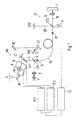
- the interferometric measuring device shown in Fig. 1 has one essential Part of a modulation interferometer arrangement MI, in which one temporal path difference of a reference beam 4 is generated, and a demodulation interferometer arrangement DI, in the one on the surface of a measurement object 7 reflected measuring beam 18 with the reference beam 4 or components brought to interference and the interfered beam to a photodetector 11 is supplied.
- a modulation interferometer arrangement MI in which one temporal path difference of a reference beam 4 is generated
- DI demodulation interferometer arrangement in the one on the surface of a measurement object 7 reflected measuring beam 18 with the reference beam 4 or components brought to interference and the interfered beam to a photodetector 11 is supplied.
- the modulation interferometer arrangement MI is from a light source 1 a collimator 2 is fed an input beam with a first beam splitter ST1 is divided into the reference beam 4 and a second sub-beam 3.
- the Reference beam 4 and the second sub-beam 3 pass through two assigned arms the modulation interferometer arrangement MI, the arm of the reference beam 4 arranged one after the other a mirror SP1, a compensation grating C1, a parallel displacement arrangement of a first and a second has acousto-optical deflector 8.9 and a retro grating 10.
- the two acousto-optical deflectors 8, 9 are controlled frequency-modulated by means of deflector drivers 12.1, 12.2.
- the deflection angle of the reference beam 4 in the first acousto-optical deflector 8 is varied by an angle a by the frequency modulation.
- the reference beam 4 is then deflected again in the direction in which it strikes the first acousto-optical deflector 8. In this way, there is a parallel offset of the reference beam 4 emerging from the second acousto-optical deflector 9, which subsequently illuminates the retro grating 10.
- the retro grating 10 is inclined at a certain angle so that the bent-back reference beam 4, regardless of the parallel offset via the two acousto-optical deflectors 8, 9, the compensation grating C1 and the mirror SP1 returns to the first beam splitter ST1.
- the second arm of the modulation interferometer arrangement MI are in the beam path of the second partial beam 3 a further mirror SP2, one after the other another compensation grid C2 and finally another retro grid 10 'arranged.
- the compensation grid C1 and the further compensation grid C2 on the one hand and the retro grid 10 and the further retro grid 10 'on the other hand are the same.
- the optical lengths of both arms of the modulation interferometer arrangement MI are unequal with a difference that is essential is greater than the coherence length of the light source 1 (e.g. a few mm).
- the compensation grid C1 provides some compensation for the spatial Decoherence of the wave fronts and the angular dispersion caused by the different Wavelengths of the required for the short coherence length Light are achieved.
- the additional dispersion caused, however, with the distance between the retro grid 10 and the compensation grid C1 increases sharply due to the corresponding grids of the other Arms of the modulation interferometer arrangement MI compensated. Because the optical The lengths of both arms are unequal and the returning reference beam interfere 4 and the second partial beam 3 at the output of the modulation interferometer arrangement MI not.
- the demodulation interferometer arrangement DI is connected.
- the demodulation interferometer arrangement DI are in turn behind second beam splitter ST2 two arms formed, in which the two from the intermediate beam 5 partial beams formed are directed.
- the one partial beam falls as Measuring beam 18 via a focusing lens 6 on the surface of the measurement object 7 and is reflected back onto the second beam splitter there.
- the other beam falls on a third mirror SP3, from where it also falls on the second Beam splitter ST2 is returned.
- the compensation measures described above can Light sources with a shorter coherence length can be used, creating a sharper Signal maximum is obtained, or with the same coherence length can improved contrast can be achieved.
- the demodulation interferometer arrangement is located at the input DI a telescope with which the incoming intermediate beam 5 is expanded to carry out a two-dimensional measurement.
- the photodetector 11 is configured as a CCD camera.
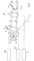
- Fig. 2 shows a further embodiment, the modulation interferometer arrangement MI is compact and doubled Amplitude of the runtime modulation is achieved.
- the light of the short-coherent light source 1 collimated with the collimator 2 and with the first beam splitter ST1 in two Partial beams divided into reference beam 4 and second partial beam 3 correspond to FIG. 1.
- the two partial beams 3, 4 are separated into the both compensation gratings C1 and C2 diffracted and pass through two acousto-optical Modulators 17.1 and 17.2.
- the acousto-optical modulators 17.1, 17.2 are minimal using the assigned modulator driver 16.1,16.2 different frequencies (e.g. 500 kHz), which means that Frequency shift of the two beams for heterodyne interferometric evaluation is enforced.
- only one can the partial beams 3, 4 pass through an acousto-optical modulator.
- both partial beams 3, 4 pass through the two acousto-optical ones Deflectors 8.9 offset in parallel.
- the two acousto-optical deflectors 8.9 are controlled with an identical signal by means of a deflector driver 12, and as a result the two partial beams 3, 4 each become parallel, in time of the control signal, shifted and assigned to respectively assigned retro grids 10, 10 ' from which they are bent back.
- the two retro grids are like this tilted that the simultaneous linear displacement of the partial beams by the acousto-optical deflectors 8.9 an opposing modulation of the transit time causes.
- the retro grids 10, 10 ' are arranged so that for both Partial beams 3,4 the optical path difference according to the embodiment 1 arises.
- the two partial beams 3, 4 after running back over the compensation gratings C1, C2 in the first beam splitter ST1 superimposed, but do not interfere due to the path difference, and passed as an intermediate beam 5 in the demodulation interferometer arrangement, the is preferably designed as a measuring probe.
Description
Die Erfindung bezieht sich auf eine interferometrische Meßvorrichtung zur Formvermessung an rauhen Oberflächen eines Meßobjekts mit einer Strahlungserzeugungseinheit, die eine kurzkohärente Eingangsstrahlung abgibt, mit einer Strahlteilervorrichtung, zum Bilden eines Referenzstrahls, der auf eine Vorrichtung mit einem reflektierenden Element zum periodischen Ändern des Lichtwegs gerichtet ist, und eines Meßstrahls, der auf das Meßobjekt gerichtet ist, mit einem Überlagerungselement, an dem der von dem Meßobjekt und der von der Vorrichtung kommende Referenzstrahl zur Interferenz gebracht werden, und mit einem Photodetektor, der die interferierte Strahlung aufnimmt und einer Auswerteeinrichtung zuführt.The invention relates to an interferometric measuring device for shape measurement on rough surfaces of a measurement object with a radiation generation unit, which emits a short coherent input radiation with a Beam splitter device, for forming a reference beam which is directed onto a device with a reflective element for periodically changing the light path is directed, and a measuring beam, which is directed to the measurement object, with a superimposition element on which that of the measurement object and that of the Device coming reference beam are brought to interference, and with a photodetector that receives the interfered radiation and an evaluation device supplies.
Eine interferometrische Meßvorrichtung dieser Art ist in der Veröffentlichung T. Dresel, G. Häusler, H. Venzke "Three-dimensional sensing of rough surfaces by coherence radar, App. Opt., Vol. 3, No. 7 vom 1.3.1992 als bekannt ausgewiesen. In dieser Veröffentlichung wird ein Interferometer mit kurzkohärenter Lichtquelle und piezobewegtem Spiegel zur Formvermessung an rauhen Oberflächen vorgeschlagen. In der Meßvorrichtung wird ein erster Teilstrahl in Form einer Referenzwelle einem weiteren Teilstrahl in Form eines Meßstrahls, der von einem Meßobjekt zurückgestrahlt ist, überlagert. Die beiden Lichtwellen haben eine sehr kurze Kohärenzlänge (einige µm), so daß der Interferenzkontrast ein Maximum erreicht, wenn die optische Wegdifferenz null ist. Zum Ändern des Lichtwegs der Referenzwelle ist das reflektierende Element in Form des piezobewegten Spiegels vorgesehen. Durch den Vergleich der Lage des piezobewegten Spiegels mit der Zeit des Auftretens des Interferenzmaximums, läßt sich der Abstand zum Meßobjekt bestimmen. Dabei können sich Schwierigkeiten in der genauen Erfassung des Interferenzmaximums und in dessen Zuordnung zu dem Lichtweg ergeben, da die eindeutige Lageerfassung des piezobewegten Spiegels aufwendig ist.An interferometric measuring device of this type is described in the publication T. Dresel, G. Häusler, H. Venzke "Three-dimensional sensing of rough surfaces by coherence radar, app. Opt., Vol. 3, No. 7 dated 1.3.1992 as known. This publication uses an interferometer with a short-coherent light source and piezo-moving mirror for shape measurement on rough surfaces proposed. A first partial beam in the form of a Reference wave another beam in the form of a measuring beam from a Measurement object is reflected back, superimposed. The two light waves have one very short coherence length (a few µm) so that the interference contrast is a maximum reached when the optical path difference is zero. For changing the light path the reference wave is the reflective element in the form of the piezo-moving Mirror provided. By comparing the location of the piezomoved Mirror with the time of occurrence of the interference maximum, the Determine the distance to the measurement object. Difficulties may arise in the exact recording of the interference maximum and in its assignment to the Light path result because the clear position detection of the piezo-moving mirror is complex.
Der Erfindung liegt die Aufgabe zugrunde, eine interferometrische Meßvorrichtung der eingangs genannten Art bereitzustellen, mit der der Aufbau vereinfacht und eine hohe Meßgenauigkeit erzielt wird.The invention has for its object an interferometric measuring device to provide the type mentioned above, with which the structure is simplified and a high measuring accuracy is achieved.
Diese Aufgabe wird mit den Merkmalen des Anspruchs 1 gelöst. Hiernach ist
also eine Modulations-Interferometeranordnung vorgesehen, die derart aufgebaut
ist, daß mit einem ersten Strahlteiler der Strahlteilervorrichtung außer dem Referenzstrahl
ein zweiter Teilstrahl gebildet wird, daß die Vorrichtung zum Ändern
des Lichtwegs eine zumindest im Strahlengang des Referenzstrahls angeordnete
parallelverschiebende Anordnung und das reflektierende Element ein Retrogitter
ist, daß im Strahlengang des Referenzstrahls vor der parallelverschiebenden
Anordnung ein Kompensationsgitter angeordnet ist, an dem der Referenzstrahl
sowohl vor als auch nach dem Durchgang durch die parallelverschiebende Anordnung
gebeugt wird, daß im Strahlengang des zweiten Teilstrahls ein gleiches
Paar wie im Strahlengang des Referenzstrahls aus einemweiteren Kompensationsgitter
und einem diesem nachgeordneten weiteren Retrogitter angeordnet
ist, wobei die optischen Weglängen der so gebildeten beiden Arme für den
Referenzstrahl und den zweiten Teilstrahl der Modulations-Interferometeranordnung
eine Differenz größer als die Kohärenzlänge aufweisen, und daß der
über das Kompensationsgitter zurückgeführte Referenzstrahl und der über das
weitere Kompensationsgitter zurückgeführte zweite Teilstrahl zu einem Zwischenstrahl
zusammengeführt werden, und daß eine Demodulations-Interferometeranordnung
vorgesehen ist, die derart aufgebaut ist, daß der Zwischenstrahl
in zwei weitere Arme der Demodulation-Interferometeranordnung mittels
eines weiteren Strahlteilers aufgeteilt wird, wobei der eine Arm von einem Spiegel
und der andere Arm von der Oberfläche des Meßobjekts abgeschlossen ist
und die beiden weiteren Arme die gleiche Wegdifferenz aufweisen wie die Arme
der Modulations-Interferometeranordnung, und daß die an dem Spiegel und der
Oberfläche des Meßobjekts zurückgelenkten Strahlen an dem Überlagerungselement
zur Interferenz gebracht werden.This object is achieved with the features of
Mittels der parallelverschiebenden Anordnung und des reflektierenden Elements in Form des Retrogitters wird eine Änderung des Lichtwegs ohne mechanisch bewegte Teile erzielt, wie in der nicht vorveröffentlichten Deutschen Patentanmeldung 197 21 842.3 ausgeführt. Durch das Kompensationsgitter im Strahlengang des Referenzstrahls wird eine Kompensation der räumlichen Dekohärenz der Wellenfronten und der durch die unterschiedlichen Wellenlängen zum Erreichen der kurzen Kohärenzlänge bedingten Winkeldispersion erzielt, wie in der ebenfalls nicht vorveröffentlichten Deutschen Patentanmeldung 197 21 884.9 bzw. EP-A-0 983 483 angegeben. Die Anwendung des Kompensationsgitters im Strahlengang des Referenzstrahls allein verursacht eine weitere Dispersion, die mit dem Abstand zwischen dem Retrogitter und dem Kompensationsgitter zunimmt. Mittels des in der Modulations-Interferometeranordnung ausgebildeten zweiten Arms mit einem gleichen Retrogitter und Kompensationsgitter wie in dem Arm des Referenzstrahls und dem angegebenen Aufbau der Demodulations-Interferometeranordnung wird diese zusätzliche Dispersion kompensiert und zusätzlich eine Trennung zwischen dem relativ großen Aufbau der Modulations-Interferometeranordnung und der relativ kompakten, als Meßsonde miniaturiesierbaren Demodulations-Interferometeranordnung realisiert, so daß die Meßvorrichtung auch leicht handhabbar ist.By means of the parallel displacement arrangement and the reflecting element in the form of the retro grid, a change in the light path without mechanical Moving parts achieved, as in the unpublished German patent application 197 21 842.3 executed. Through the compensation grid in the beam path The reference beam compensates for spatial decoherence of the wavefronts and the different wavelengths to reach them the short coherence length caused angular dispersion, as in the also unpublished German patent application 197 21 884.9 or EP-A-0 983 483. The application of the compensation grid in the beam path of the reference beam alone causes another dispersion that with the distance between the retro grid and the compensation grid increases. By means of the in of the modulation interferometer arrangement is formed with a second arm same retro grating and compensation grating as in the arm of the reference beam and the specified structure of the demodulation interferometer arrangement this additional dispersion is compensated and an additional one Separation between the relatively large structure of the modulation interferometer arrangement and the relatively compact, miniaturizable as a measuring probe Demodulation interferometer arrangement realized so that the measuring device is also easy to handle.
Für einen einfachen Aufbau und eine einfache Ansteuerung der Meßvorrichtung sind die Maßnahmen günstig, daß die parallelverschiebende Anordnung eine im Strahlengang angeordnete akustooptische Deflektoreinrichtung aufweist, und daß die Deflektoreinrichtung frequenzmoduliert angesteuert ist und in bezug auf den ankommenden Referenzstrahl sowie auf das Refeixionsgitter derart angeordnet ist, daß der zu dem Überlagerungselement geführte Referenzstrahl durch seine Ablenkung in der Deflektoreinrichtung die Änderung seines Lichtwegs erfährt. Hierdurch kann der Lichtweg in genau definierter Weise einfach verändert und das Interferenzmaximum in Abhängigkeit des Lichtwegs eindeutig bestimmt werden.For simple construction and simple control of the measuring device the measures are favorable that the parallel displacement arrangement in a Beam path arranged acousto-optical deflector device, and that the deflector device is controlled frequency modulated and in relation to the incoming reference beam and arranged on the reflection grid in such a way is that the reference beam led to the overlay element its deflection in the deflector device experiences the change in its light path. As a result, the light path can easily be changed in a precisely defined manner and the interference maximum is clearly determined as a function of the light path become.
Ist vorgesehen, daß die Gitterkonstante des Kompensationsgitters und des zweiten Kompensationsgitters zweimal so groß ist wie die Gitterkonstante des Retrogitters bzw. des weiteren Retrogitters, so werden die Winkeldispersion und die räumliche Dekohärenz der Wellenfronten besonders gut beseitigt.It is provided that the lattice constant of the compensation grid and second compensation grid is twice the grid constant of the Retrogitters or the further retrogrid, so the angular dispersion and the spatial decoherence of the wave fronts is particularly well eliminated.
Zur Kompensation der räumlichen Dekohärenz ist weiterhin die Maßnahme vorteilhaft, daß das Kompensationsgitter und das Retrogitter sowie das weitere Kompensationsgitter und das weitere Retrogitter jeweils parallel zueinander angeordnet sind. The measure continues to compensate for spatial decoherence advantageous that the compensation grid and the retro grid and the other Compensation grid and the further retro grid each parallel to each other are arranged.
Der Aufbau wird weiterhin dadurch vereinfacht, daß die Kompensationsgitter reflektierend ausgebildet sind, daß im Strahlengang des Referenzstrahls und des zweiten Teilstrahls zwischen dem ersten Strahlteiler und den Kompensationsgittern jeweils ein Spiegel angeordnet ist, mit dem der Referenzstrahl bzw. der zweite Teilstrahl auf dem Hinweg auf das zugehörige Kompensationsgitter und auf seinem Rückweg auf den Strahlteiler gerichtet ist, der den Zwischenstrahl erzeugt, und dadurch, daß der weitere Strahlteiler gleichzeitig das Überlagerungselement bildet.The structure is further simplified in that the compensation grid are designed reflective that in the beam path of the reference beam and second partial beam between the first beam splitter and the compensation grids In each case a mirror is arranged with which the reference beam or second partial beam on the way to the associated compensation grid and on its way back is aimed at the beam splitter, which is the intermediate beam generated, and in that the further beam splitter simultaneously the overlay element forms.
Für die einfache Handhabung ist günstig vorgesehen, daß die Demodulations-Interferometeranordnung über einen Lichtleiter mit der Modulations-Interferometeranordnung gekoppelt ist.For easy handling, it is advantageously provided that the demodulation interferometer arrangement via a light guide with the modulation interferometer arrangement is coupled.
Eine flächenhafte Auswertung wird dadurch ermöglicht, daß der Zwischenstrahl am Eingang der Demodulations-Interferometeranordnung durch eine Fernrohranordnung zu einem breiten Lichtstrahl aufgeweitet wird und daß der Photodetektor als CCD-Kamera ausgebildet ist.A two-dimensional evaluation is made possible by the fact that the intermediate beam at the entrance of the demodulation interferometer arrangement through a telescope arrangement is expanded to a broad beam of light and that the photodetector is designed as a CCD camera.
Für die Meßwerterfassung und Steigerung der Meßgenauigkeit ist vorgesehen, daß ein Aufbau für eine an sich bekannte heterodyn-interferometrische Auswertung vorhanden ist, wobei eine Einrichtung zur Frequenzverschiebung zwischen den interferierenden Strahlen vorgesehen ist.For the acquisition of measured values and increasing the accuracy of the measurement, that a setup for a known heterodyne interferometric evaluation is present, with a device for frequency shift between the interfering rays is provided.
Ein vorteilhafter Aufbau für eine einfache Meßanordnung besteht darin, daß die parallelverschiebende Anordnung nur in dem den Referenzstrahl führenden Arm der Modulations-Interferometeranordnung angeordnet ist. An advantageous structure for a simple measuring arrangement is that the parallel displacement arrangement only in the arm guiding the reference beam the modulation interferometer arrangement is arranged.
Um auch die Modulations-Interferometeranordnung kompakt auszubilden, besteht ein weiterer vorteilhafter Aufbau darin, daß die parallelverschiebende Anordnung in beiden Armen der Modulations-Interferometeranordnung derart angeordnet ist, daß sie sowohl auf dem Hinweg als auch auf dem Rückweg von dem Referenzstrahl und von dem zweiten Teilstrahl durchlaufen wird. Dieser Aufbau wird weiterhin dadurch vereinfacht, daß das Retrogitter für den Referenzstrahl und das weitere Retrogitter für den zweiten Teilstrahl so gekippt sind, daß die gleichzeitige Verschiebung des Referenzstrahls und des zweiten Teilstrahls eine gegenläufige Modulation ihrer Laufzeit bewirkt, und daß die beiden Retrogitter so angeordnet sind, daß für den Referenzstrahl und den zweiten Teilstrahl die optische Wegdifferenz entsteht.In order to make the modulation interferometer arrangement compact, there is a further advantageous structure in that the parallel displacement arrangement arranged in both arms of the modulation interferometer arrangement is that on the way there as well as on the way back from the Reference beam and is traversed by the second beam. This Construction is further simplified in that the retro grating for the reference beam and the further retro grid for the second partial beam is tilted so that the simultaneous displacement of the reference beam and the second sub-beam an opposite modulation of their duration causes, and that the two Retro gratings are arranged so that for the reference beam and the second partial beam the optical path difference arises.
Dabei besteht eine günstige Anordnung für eine heterodyn-interferometrische Auswertung darin, daß zwischen den beiden Kompensationsgittern und der parallelverschiebenden Anordnung jeweils ein akustooptischer Modulator angeordnet ist und daß die akustooptischen Modulatoren zum Erzeugen einer Frequenzverschiebung des Referenzstrahls des zweiten Teilstrahls mit geringfügig unterschiedlicher Frequenz mittels zugeordneter Modulator-Treiber angesteuert werden. Dabei kompensieren sich die beiden akustooptischen Modulatoren gegenseitig. Alternativ dazu kann auch nur ein akustooptischer Modulator eingesetzt werden in der Weise, daß nur ein akustooptischer Modulator in einem der beiden Arme der Modulations-Interferometeranordnung auf der den Retrogittern abgewandten Seite der parallelverschiebenden Anordnung vorgesehen ist.There is a favorable arrangement for a heterodyne interferometric Evaluation in that between the two compensation grids and the parallel shifting Arrangement each arranged an acousto-optical modulator and that the acousto-optic modulators for generating a frequency shift of the reference beam of the second sub-beam with slightly different frequency controlled by means of assigned modulator drivers become. The two acousto-optical modulators compensate each other. Alternatively, only an acousto-optic modulator can be used are such that only one acousto-optical modulator in one of the two arms of the modulation interferometer arrangement on that of the retro grids facing away from the parallel displacement arrangement is.
Hinsichtlich der Wirkungsweise der heterodyn-interferometrischen Verfahren an sich wird auf die diesbezügliche Literatur verwiesen. Regarding the mode of operation of the heterodyne interferometric method reference is made to the relevant literature.
Die Erfindung wird nachfolgend anhand von Ausführungsbeispielen unter Bezugnahme auf die Zeichnungen näher erläutert. Es zeigen:
- Fig. 1
- ein erstes Ausführungsbeispiel der interferometrischen Meßvorrichtung mit einer Modulations-Interferometeranordnung und einer nachgeschalteten Demodulations-Interferometeranordnung und
- Fig. 2
- ein weiteres Ausführungsbeispiel für eine Modulations-Interferometeranordnung der Meßvorrichtung.
- Fig. 1
- a first embodiment of the interferometric measuring device with a modulation interferometer arrangement and a downstream demodulation interferometer arrangement and
- Fig. 2
- a further embodiment of a modulation interferometer arrangement of the measuring device.
Die in Fig. 1 gezeigte interferometrische Meßvorrichtung weist als einen wesentlichen
Bestandteil eine Modulations-Interferometeranordnung MI auf, in der eine
zeitliche Wegdifferenz eines Referenzstrahls 4 erzeugt wird, sowie eine Demodulations-Interferometeranordnung
DI, in der ein an der Oberfläche eines Meßobjekts
7 reflektierter Meßstrahl 18 mit dem Referenzstrahl 4 bzw. Bestandteilen
desselben zur Interferenz gebracht und der interferierte Strahl einem Photodetektor
11 zugeführt wird.The interferometric measuring device shown in Fig. 1 has one essential
Part of a modulation interferometer arrangement MI, in which one
temporal path difference of a
Der Modulations-Interferometeranordnung MI wird von einer Lichtquelle 1 über
einen Kollimator 2 ein Eingangsstrahl zugeführt, der mit einem ersten Strahlteiler
ST1 in den Referenzstrahl 4 und einen zweiten Teilstrahl 3 aufgeteilt wird. Der
Referenzstrahl 4 und der zweite Teilstrahl 3 durchlaufen zwei zugeordnete Arme
der Modulations-Interferometeranordnung MI, wobei der Arm des Referenzstrahls
4 nacheinander angeordnet einen Spiegel SP1, ein Kompensationsgitter
C1, eine parallelverschiebende Anordnung aus einem ersten und einem zweiten
akustooptischen Deflektor 8,9 sowie ein Retrogitter 10 aufweist. The modulation interferometer arrangement MI is from a light source 1
a
Die beiden akustooptischen Deflektoren 8,9 werden mittels Deflektor-Treibern
12.1,12.2 frequenzmoduliert angesteuert. Durch die Frequenzmodulation wird
der Ablenkwinkel des Referenzstrahl 4 in dem ersten akustooptischen Deflektor
8 um einen Winkel a variiert. In dem zweiten akustooptischen Deflektor 9 wird
der Referenzstrahl 4 anschließend wieder in die Richtung abgelenkt, in der er auf
den ersten akustooptischen Deflektor 8 auftrifft. Auf diese Weise entsteht ein
Parallelversatz des aus dem zweiten akustooptischen Deflektor 9 austretenden
Referenzstrahls 4, der anschließend das Retrogitter 10 beleuchtet. Das Retrogitter
10 ist unter einem bestimmten Winkel so geneigt, daß der zurückgebeugte
Referenzstrahl 4 unabhängig von dem Parallelversatz über die beiden akustooptischen
Deflektoren 8,9, das Kompensationsgitter C1 und den Spiegel SP1 zu
dem ersten Strahlteiler ST1 zurückläuft.The two acousto-
In dem zweiten Arm der Modulations-Interferometeranordnung MI sind im Strahlengang
des zweiten Teilstrahls 3 nacheinander ein weiterer Spiegel SP2, ein
weiteres Kompensationsgitter C2 sowie abschließend ein weiteres Retrogitter
10' angeordnet. Das Kompensationsgitter C1 und das weitere Kompensationsgitter
C2 einerseits sowie das Retrogitter 10 und das weitere Retrogitter
10' andererseits sind gleich. Die optischen Längen beider Arme der Modulations-Interferometeranordnung
MI sind ungleich mit einer Differenz, die wesentlich
größer als die Kohärenzlänge der Lichtquelle 1 ist (z. B. einige mm).In the second arm of the modulation interferometer arrangement MI are in the beam path
of the second partial beam 3 a further mirror SP2, one after the other
another compensation grid C2 and finally another retro grid
10 'arranged. The compensation grid C1 and the further compensation grid
C2 on the one hand and the
Durch das Kompensationsgitter C1 wird eine gewisse Kompensation der räumlichen
Dekohärenz der Wellenfronten und der Winkeldispersion, die durch die unterschiedlichen
Wellenlängen des für die kurze Kohärenzlänge erforderlichen
Lichts bedingt sind, erreicht. Die dabei jedoch verursachte zusätzliche Dispersion,
die mit dem Abstand zwischen dem Retrogitter 10 und dem Kompensationsgitter
C1 stark zunimmt, wird durch die entsprechenden Gitter des anderen
Arms der Modulations-Interferometeranordnung MI kompensiert. Da die optischen
Längen beider Arme ungleich sind interferieren der zurückkehrende Referenzstrahl
4 und der zweite Teilstrahl 3 am Ausgang der Modulations-Interferometeranordnung
MI nicht.The compensation grid C1 provides some compensation for the spatial
Decoherence of the wave fronts and the angular dispersion caused by the different
Wavelengths of the required for the short coherence length
Light are achieved. The additional dispersion caused, however,
with the distance between the
Nachdem der Referenzstrahl 4 und der zweite Teilstrahl 3 an dem ersten Strahlteiler
ST1 zusammengeführt sind, werden sie als Zwischenstrahl 5 über eine
Linse 14 in einen Lichtleiter 19 geführt, an dessen Ausgang über eine weitere
Linse 15 die Demodulations-Interferometeranordnung DI angeschlossen ist. In
der Demodulations-Interferometeranordnung DI sind wiederum hinter einem
zweiten Strahlteiler ST2 zwei Arme gebildet, in die die beiden aus dem Zwischenstrahl
5 gebildeten Teilstrahlen geleitet werden. Der eine Teilstrahl fällt als
Meßstrahl 18 über eine Fokussierungslinse 6 auf die Oberfläche des Meßobjekts
7 und wird dort auf den zweiten Strahlteiler zurückreflektiert. Der andere Teilstrahl
fällt auf einen dritten Spiegel SP3, von wo er ebenfalls auf den zweiten
Strahlteiler ST2 zurückgeführt wird. Die beiden Arme der Demodulations-Interferometeranordnung
DI, das z. B. wie die Modulations-Interferometeranordnung
MI als Michelson Interferometer aufgebaut ist, haben die gleiche optische Wegdifferenz
wie die Arme der Modulations-Interferometeranordnung MI. Aus diesem
Grund interferieren die beiden an dem zweiten Strahlteiler zusammentreffenden
Teilstrahlen in Form des Meßstrahls 18 und des anderen Teilstrahls
20. Der interferierte Strahl wird dem Photodetektor 11 zugeführt, der das
Signalmaximum des Interferenzkontrasts, das durch die kurze Kohärenzlänge des
von der Lichtquelle 1 abgegebenen Eingangsstrahls entsteht, erfaßt und einer
Auswerteschaltung 13 zuführt. Durch den Vergleich des Zeitpunkts des Signalmaximums
mit der momentanen Frequenz der Deflektor-Treiber läßt sich der
Abstand zum Meßobjekt 7 und damit die Form der Oberfläche bestimmen, wie
beispielsweise in der Deutschen Patentanmeldung 197 21 842 ausgeführt. After the
Dabei können durch die vorstehend beschriebenen Kompensationsmaßnahmen Lichtquellen mit kürzerer Kohärenzlänge verwendet werden, wodurch ein schärferes Signalmaximum erhalten wird, oder bei gleicher Kohärenzlänge kann ein verbesserter Kontrast erzielt werden.The compensation measures described above can Light sources with a shorter coherence length can be used, creating a sharper Signal maximum is obtained, or with the same coherence length can improved contrast can be achieved.
In einer weiteren Ausgestaltung befindet sich am Eingang der Demodulations-Interferometeranordnung
DI ein Fernrohr, mit dem der eintreffende Zwischenstrahl
5 aufgeweitet wird, um eine flächenhafte Messung durchzuführen. Bei dieser
Anordnung ist der Photodetektor 11 als CCD-Kamera ausgebildet.In a further embodiment, the demodulation interferometer arrangement is located at the input
DI a telescope with which the incoming
Fig. 2 zeigt ein weiteres Ausführungsbeispiel, wobei die Modulations-Interferometeranordnung MI kompakt aufgebaut ist und eine Verdoppelung der Amplitude der Laufzeitmodulation erzielt wird.Fig. 2 shows a further embodiment, the modulation interferometer arrangement MI is compact and doubled Amplitude of the runtime modulation is achieved.
Bei der Anordnung gemäß Fig. 2 wird das Licht der kurzkohärenten Lichtquelle
1 mit dem Kollimator 2 kollimiert und mit dem ersten Strahlteiler ST1 in zwei
Teilstrahlen aufgeteilt, die dem Referenzstrahl 4 und dem zweiten Teilstrahl 3
gemäß Fig. 1 entsprechen. Die beiden Teilstrahlen 3,4 werden getrennt in den
beiden Kompensationsgittern C1 und C2 gebeugt und durchlaufen zwei akustooptische
Modulatoren 17.1 und 17.2. Die akustooptischen Modulatoren 17.1,
17.2 werden mittels zugeordneter Modulator-Treiber 16.1,16.2 mit geringfügig
unterschiedlichen Frequenzen (z. B. 500 kHz) angesteuert, wodurch eine
Frequenzverschiebungbeider Teilstrahlenzur heterodyn-interferometrischen Auswertung
erzwungen wird. In einer anderen Ausführungsform kann auch nur einer
der Teilstrahlen 3,4 durch einen akustooptischen Modulator hindurchlaufen. Im
weiteren Verlauf durchlaufen beide Teilstrahlen 3,4 die beiden akustooptischen
Deflektoren 8,9 parallel versetzt. Die beiden akustooptischen Deflektoren 8,9
werden hierbei mit identischem Signal mittels eines Deflektor-Treibers 12 gesteuert,
und dadurch werden die beiden Teilstrahlen 3,4 jeweils parallel, im Takt
des Steuersignals, verschoben und auf jeweils zugeordnete Retrogitter 10,10'
gerichtet, von denen sie zurückgebeugt werden. Die beiden Retrogitter sind so
gekippt, daß die gleichzeitige lineare Verschiebung der Teilstrahlen durch die
akustooptischen Deflektoren 8,9 eine gegenläufige Modulation der Laufzeit
bewirkt. Außerdem sind die Retrogitter 10,10' so angeordnet, daß für beide
Teilstrahlen 3,4 die optische Wegdifferenz entsprechend dem Ausführungsbeispiel
gemäß Fig. 1 entsteht. Auch hierbei werden die beiden Teilstrahlen 3,4
nach Zurücklaufen über die Kompensationsgitter C1, C2 in dem ersten Strahlteiler
ST1 überlagert, wobei sie infolge der Wegdifferenz nicht interferieren, und
als Zwischenstrahl 5 in die Demodulations-Interferometeranordnung geleitet, die
vorzugsweise als Meßsonde ausgebildet ist.2, the light of the short-coherent
Auch hierbei sind das Kompensationsgitter C1 und das zugeordnete Retrogitter
10 einerseits und das weitere Kompensationsgitter C2 und das weitere Retrogitter
10' andererseits parallel zueinander angeordnet, wobei jedoch die beiden
Paare entgegengesetzt, aber unter gleichem Winkel bezüglich der parallel austretenden
bzw. einfallenden Teilstrahlen 3,4 gekippt sind.Here, too, are the compensation grid C1 and the associated
Mit den beschriebenen Maßnahmen ergibt sich ohne mechanisch bewegte Teile eine Hohe Meßgenauigkeit, wobei der Aufbau insbesondere hinsichtlich der zu handhabenden Meßsonde, die lediglich die Bauteile der Demodulations-Interferometeranordnung aufweist, äußerst kompakt ist.With the measures described, there are no mechanically moving parts a high measuring accuracy, the structure in particular with regard to handling measuring probe, which is only the components of the demodulation interferometer arrangement has, is extremely compact.
Claims (14)
- Interferometric measuring device for form measurement on rough surfaces of a measurement object (7), having a radiation production unit (1) which emits short-coherent input radiation, having a beam splitter device (ST1, ST2) for forming a reference beam (4) which is directed at a device (8, 9) with a reflective element (10) for periodically changing the light path, and of a measurement beam (18) which is directed at the measurement object (7), having a superimposition element (ST2) at which the measurement beam (18) coming from the measurement object (7) and the reference beam (4) coming from the device (8, 9, 10) are caused to interfere, and having a photodetector (11) which records the interfering radiation and feeds it to an evaluation device (13),
in which case, furthermore,
a modulation interferometer arrangement (MI) is provided which is designed in such a way that apart from the reference beam (4) a second component beam (3) is formed with the aid of a first beam splitter (ST1) of the beam splitter device,
the device (8, 9, 10) for changing the light path is a parallel-shifting arrangement (8, 9) arranged at least in the beam path of the reference beam (4), and the reflective element is a retrograting (10),
arranged in the beam path of the reference beam upstream of the parallel-shifting arrangement (8, 9) is a compensation grating (C1) at which the reference beam (4) is diffracted both before and after passing through the parallel-shifting arrangement (8, 9),
arranged in the beam path of the second component beam (3), as in the beam path of the reference beam (4), is an identical pair composed of a further compensation grating (C2) and a further retrograting (10'), arranged downstream of the latter, the optical path lengths of the two arms thus formed for the reference beam (4) and the second component beam (3) of the modulation interferometer arrangement (MI) having a difference greater than the coherence length,
the reference beam (4) returned via the compensation grating (C1), and the second component beam (3) returned via the further compensation grating (C2) are combined to form an intermediate beam (5) and
a demodulation interferometer arrangement (DI) is provided which is arranged in such a way
that the intermediate beam (5) is split up into two further arms of the demodulation interferometer arrangement (DI) by means of a further beam splitter (ST2), with one arm being terminated by a mirror (SP3) and the other arm being terminated by the surface of the measurement object (7), and the two further arms have the same path difference as the arms of the modulation interferometer arrangement (MI), and
that the beams returned at the mirror (3) and the surface of the measurement object (7) are caused to interfere at the superimposition element (ST2). - Measuring device according to Claim 1, in which the parallel-shifting arrangement has an acousto-optical deflector device (8, 9) arranged in the beam path, and
the deflector device (8, 9) is driven such that it is frequency-modulated and, with respect to the incoming reference beam (4) and to the reflection grating (10), is arranged in such a manner that the reference beam (4) passed to the superimposition element (ST2) experiences a change in its light path due to this deflection in the deflector device (8, 9). - Measuring device according to Claim 2, in which the grating constant of the compensation grating (C1) and of the second compensation grating (C2) is twice as great as the grating constant of the retrograting (10) and of the second retrograting (10'), respectively.
- Measuring device according to Claim 2 or 3, in which the compensation grating (C1) and the retrograting (10) as well as the further compensation grating (C2) and the further retrograting (10') are respectively arranged parallel to one another.
- Measuring device according to one of the preceding claims, in which the compensation gratings (C1, C2) are of reflective design, and there is respectively arranged in the beam path of the reference beam (4) between the first beam splitter (ST1) and the compensation gratings (C1, C2) a mirror (SP1, SP2) with which the reference beam (4) and the second component beam (3), respectively, are directed on the forward path at the associated compensation grating (C1, C2), and on its return path at the beam splitter (ST1), which generates the intermediate beam (5).
- Measuring device according to one of the preceding claims, in which the further beam splitter (ST2) at the same time forms the superimposition element.
- Measuring device according to one of the preceding claims, in which the demodulation interferometer arrangement (DI) is coupled to a light guide (19) by means of the modulation interferometer arrangement (MI).
- Measuring device according to one of the preceding claims, in which at the input of the demodulation interferometer arrangement (DI) the intermediate beam (5) is expanded by a telescope arrangement to form a wide light beam, and the photodetector (11) is designed as a CCD camera.
- Measuring device according to one of the preceding claims, in which there is a design for a heterodyne interferometric evaluation, known per se, a device being provided for frequency shifting between the interfering beams.
- Measuring device according to one of the preceding claims, in which the parallel-shifting arrangement (8, 9) is arranged only in that arm of the modulation interferometer arrangement (MI) which guides the reference beam (4).
- Measuring device according to one of Claims 1 to 9, in which the parallel-shifting arrangement (8, 9) is arranged in both arms of the modulation interferometer arrangement (MI) in such a way that it is traversed both on the forward path and on the return path by the reference beam (4) and by the second component beam (3).
- Measuring device according to Claim 11, in which the retrograting (10) for the reference beam (4), and the further retrograting (10') for the second component beam (3) are tilted such that the simultaneous displacement of the reference beam (4) and of the second component beam (3) effects an oppositely directed modulation of their transit time, and in which the two retrogratings (10, 10') are arranged so as to produce the optical path difference for the reference beam (4) and the second component beam (3).
- Measuring device according to Claim 11 or 12, in which an acousto-optical modulator (17.1, 17.2) is respectively arranged between the two compensation gratings (C1, C2) and the parallel-shifting arrangement, and in which the acousto-optical modulators (17.1, 17.2) for generating a frequency shift of the reference beam (4) and of the second component beam (3) are driven at a slightly different frequency by means of assigned modulator drivers (16.1, 16.2).
- Measuring device according to Claim 11 or 12, in which only one acousto-optical modulator is provided in one of the two arms of the modulation interferometer arrangement (MI) on the side of the parallel-shifting arrangement averted from the retrogratings (10, 10').
Applications Claiming Priority (3)
| Application Number | Priority Date | Filing Date | Title |
|---|---|---|---|
| DE19738900A DE19738900B4 (en) | 1997-09-05 | 1997-09-05 | Interferometric measuring device for shape measurement on rough surfaces |
| DE19738900 | 1997-09-05 | ||
| PCT/DE1998/002564 WO1999013294A1 (en) | 1997-09-05 | 1998-09-01 | Interferometric measuring device for form measurement on rough surfaces |
Publications (2)
| Publication Number | Publication Date |
|---|---|
| EP0937229A1 EP0937229A1 (en) | 1999-08-25 |
| EP0937229B1 true EP0937229B1 (en) | 2004-12-01 |
Family
ID=7841334
Family Applications (1)
| Application Number | Title | Priority Date | Filing Date |
|---|---|---|---|
| EP98951246A Expired - Lifetime EP0937229B1 (en) | 1997-09-05 | 1998-09-01 | Interferometric measuring device for form measurement on rough surfaces |
Country Status (5)
| Country | Link |
|---|---|
| US (1) | US6064482A (en) |
| EP (1) | EP0937229B1 (en) |
| DE (2) | DE19738900B4 (en) |
| ES (1) | ES2232967T3 (en) |
| WO (1) | WO1999013294A1 (en) |
Families Citing this family (6)
| Publication number | Priority date | Publication date | Assignee | Title |
|---|---|---|---|---|
| DE19721884C1 (en) * | 1997-05-26 | 1998-06-04 | Bosch Gmbh Robert | Interferometric measuring arrangement for sensing rough surfaces |
| DE10244553B3 (en) * | 2002-09-25 | 2004-02-05 | Robert Bosch Gmbh | Interferometric measuring device for detecting shape, roughness of distance of object surface has beam from modulation interferometer fed to optical measuring probe with angled light output surface |
| DE10244552B3 (en) * | 2002-09-25 | 2004-02-12 | Robert Bosch Gmbh | Interferometric measuring device for determining the shape, roughness or distance of the surface of a measurement object comprises a measurement probe coupled to an interferometer via an optical fiber arrangement |
| DE102004045802B4 (en) | 2004-09-22 | 2009-02-05 | Robert Bosch Gmbh | Interferometric system with reference surface with a mirrored zone |
| CN101718520B (en) * | 2009-11-16 | 2011-01-05 | 浙江大学 | System for quickly measuring surface quality |
| CN101949690B (en) * | 2010-08-24 | 2012-08-22 | 中国科学院光电技术研究所 | Optical surface shape detection device and method |
Citations (1)
| Publication number | Priority date | Publication date | Assignee | Title |
|---|---|---|---|---|
| EP0983483A1 (en) * | 1997-05-26 | 2000-03-08 | Robert Bosch Gmbh | Interferometric measuring device |
Family Cites Families (8)
| Publication number | Priority date | Publication date | Assignee | Title |
|---|---|---|---|---|
| GB2128734B (en) * | 1982-10-08 | 1986-02-19 | Nat Res Dev | Irradiative probe system |
| US4848908A (en) * | 1983-10-24 | 1989-07-18 | Lockheed Missiles & Space Company, Inc. | Optical heterodyne roughness measurement system |
| JPH0287005A (en) * | 1988-09-26 | 1990-03-27 | Brother Ind Ltd | Optical heterodyne interference surface shape measuring apparatus |
| US5064257A (en) * | 1990-04-06 | 1991-11-12 | Hamamatsu Photonics K.K. | Optical heterodyne scanning type holography device |
| CH693968A5 (en) * | 1993-04-21 | 2004-05-14 | Fraunhofer Ges Forschung | Method and apparatus for the Topographiepruefung of surfaces. |
| DE19522262C2 (en) * | 1995-06-20 | 1997-05-22 | Zeiss Carl Jena Gmbh | Heterodyne interferometer arrangement |
| DE19721843C1 (en) * | 1997-05-26 | 1999-02-11 | Bosch Gmbh Robert | Interferometric measuring device |
| DE19721842C2 (en) * | 1997-05-26 | 1999-04-01 | Bosch Gmbh Robert | Interferometric measuring device |
-
1997
- 1997-09-05 DE DE19738900A patent/DE19738900B4/en not_active Expired - Fee Related
-
1998
- 1998-09-01 ES ES98951246T patent/ES2232967T3/en not_active Expired - Lifetime
- 1998-09-01 DE DE59812331T patent/DE59812331D1/en not_active Expired - Lifetime
- 1998-09-01 EP EP98951246A patent/EP0937229B1/en not_active Expired - Lifetime
- 1998-09-01 WO PCT/DE1998/002564 patent/WO1999013294A1/en active IP Right Grant
- 1998-09-01 US US09/297,695 patent/US6064482A/en not_active Expired - Fee Related
Patent Citations (1)
| Publication number | Priority date | Publication date | Assignee | Title |
|---|---|---|---|---|
| EP0983483A1 (en) * | 1997-05-26 | 2000-03-08 | Robert Bosch Gmbh | Interferometric measuring device |
Also Published As
| Publication number | Publication date |
|---|---|
| WO1999013294A1 (en) | 1999-03-18 |
| DE59812331D1 (en) | 2005-01-05 |
| US6064482A (en) | 2000-05-16 |
| ES2232967T3 (en) | 2005-06-01 |
| DE19738900A1 (en) | 1999-03-18 |
| DE19738900B4 (en) | 2005-07-14 |
| EP0937229A1 (en) | 1999-08-25 |
Similar Documents
| Publication | Publication Date | Title |
|---|---|---|
| DE19721843C1 (en) | Interferometric measuring device | |
| EP1923673B1 (en) | Position measuring device | |
| DE3816247C2 (en) | Device for measuring a relative movement of two objects that can be moved relative to one another | |
| DE2003492A1 (en) | Measuring method for step encoders for measuring lengths or angles as well as arrangements for carrying out this measuring method | |
| DE102004037137A1 (en) | Object`s distance measurement method, involves providing electrical reference signal to time-of-flight unit, mixing electromagnetic radiation falling on unit with reference signal and detecting delay time between signal and radiation | |
| DE19930687B4 (en) | Optical displacement measuring system | |
| DE102005042954B4 (en) | Apparatus and method for determining velocity profiles in arbitrarily directed flows | |
| DE19721882C2 (en) | Interferometric measuring device | |
| DE19628200A1 (en) | Device and method for performing interferometric measurements | |
| DE19721881C2 (en) | Interferometric measuring device | |
| EP0491749B1 (en) | Device for absolute two-dimensional position measurement | |
| EP0112399B1 (en) | Interferential measuring method for surfaces | |
| DE4400680C2 (en) | Device for determining changes in distance of an object | |
| EP3477264B1 (en) | Optical positioning device | |
| EP0937229B1 (en) | Interferometric measuring device for form measurement on rough surfaces | |
| DE19721842C2 (en) | Interferometric measuring device | |
| EP0610374B1 (en) | Process for measuring the inclination of boundary areas in an optical system | |
| DE3730091A1 (en) | INTERFEROMETRIC DISTANCE MEASURING DEVICE | |
| DE19721883C2 (en) | Interferometric measuring device | |
| DE19721884C1 (en) | Interferometric measuring arrangement for sensing rough surfaces | |
| DE102009027266A1 (en) | Interferometric displacement and / or rotary measuring device | |
| DE3816755C3 (en) | Device for contactless detection of the surface deflection of a test object caused by ultrasonic waves | |
| EP3742956B1 (en) | Method for generating a two-dimensional interferogram using a michelson-type free beam interferometer | |
| DE3233483C2 (en) | Method and device for measuring velocity components with the aid of relative laser Doppler anemometry | |
| EP0021048B1 (en) | Apparatus for contactless photoeletric measurement of the speed of objects moving in a space |
Legal Events
| Date | Code | Title | Description |
|---|---|---|---|
| PUAI | Public reference made under article 153(3) epc to a published international application that has entered the european phase |
Free format text: ORIGINAL CODE: 0009012 |
|
| AK | Designated contracting states |
Kind code of ref document: A1 Designated state(s): DE ES FR GB IT |
|
| 17P | Request for examination filed |
Effective date: 19990920 |
|
| GRAP | Despatch of communication of intention to grant a patent |
Free format text: ORIGINAL CODE: EPIDOSNIGR1 |
|
| GRAS | Grant fee paid |
Free format text: ORIGINAL CODE: EPIDOSNIGR3 |
|
| GRAA | (expected) grant |
Free format text: ORIGINAL CODE: 0009210 |
|
| AK | Designated contracting states |
Kind code of ref document: B1 Designated state(s): DE ES FR GB IT |
|
| REG | Reference to a national code |
Ref country code: GB Ref legal event code: FG4D Free format text: NOT ENGLISH |
|
| REF | Corresponds to: |
Ref document number: 59812331 Country of ref document: DE Date of ref document: 20050105 Kind code of ref document: P |
|
| REG | Reference to a national code |
Ref country code: ES Ref legal event code: FG2A Ref document number: 2232967 Country of ref document: ES Kind code of ref document: T3 |
|
| GBT | Gb: translation of ep patent filed (gb section 77(6)(a)/1977) |
Effective date: 20050518 |
|
| ET | Fr: translation filed | ||
| PLBE | No opposition filed within time limit |
Free format text: ORIGINAL CODE: 0009261 |
|
| STAA | Information on the status of an ep patent application or granted ep patent |
Free format text: STATUS: NO OPPOSITION FILED WITHIN TIME LIMIT |
|
| 26N | No opposition filed |
Effective date: 20050902 |
|
| PGFP | Annual fee paid to national office [announced via postgrant information from national office to epo] |
Ref country code: ES Payment date: 20090928 Year of fee payment: 12 |
|
| PGFP | Annual fee paid to national office [announced via postgrant information from national office to epo] |
Ref country code: GB Payment date: 20090922 Year of fee payment: 12 |
|
| PGFP | Annual fee paid to national office [announced via postgrant information from national office to epo] |
Ref country code: DE Payment date: 20091120 Year of fee payment: 12 |
|
| PGFP | Annual fee paid to national office [announced via postgrant information from national office to epo] |
Ref country code: IT Payment date: 20090924 Year of fee payment: 12 |
|
| GBPC | Gb: european patent ceased through non-payment of renewal fee |
Effective date: 20100901 |
|
| PG25 | Lapsed in a contracting state [announced via postgrant information from national office to epo] |
Ref country code: IT Free format text: LAPSE BECAUSE OF NON-PAYMENT OF DUE FEES Effective date: 20100901 |
|
| REG | Reference to a national code |
Ref country code: FR Ref legal event code: ST Effective date: 20110531 |
|
| REG | Reference to a national code |
Ref country code: DE Ref legal event code: R119 Ref document number: 59812331 Country of ref document: DE Effective date: 20110401 |
|
| PG25 | Lapsed in a contracting state [announced via postgrant information from national office to epo] |
Ref country code: FR Free format text: LAPSE BECAUSE OF NON-PAYMENT OF DUE FEES Effective date: 20100930 Ref country code: DE Free format text: LAPSE BECAUSE OF NON-PAYMENT OF DUE FEES Effective date: 20110401 |
|
| PG25 | Lapsed in a contracting state [announced via postgrant information from national office to epo] |
Ref country code: GB Free format text: LAPSE BECAUSE OF NON-PAYMENT OF DUE FEES Effective date: 20100901 |
|
| PGFP | Annual fee paid to national office [announced via postgrant information from national office to epo] |
Ref country code: FR Payment date: 20091005 Year of fee payment: 12 |
|
| REG | Reference to a national code |
Ref country code: ES Ref legal event code: FD2A Effective date: 20111019 |
|
| PG25 | Lapsed in a contracting state [announced via postgrant information from national office to epo] |
Ref country code: ES Free format text: LAPSE BECAUSE OF NON-PAYMENT OF DUE FEES Effective date: 20100902 |