EP0936422B1 - Apparatus having refrigeration cycle - Google Patents
Apparatus having refrigeration cycle Download PDFInfo
- Publication number
- EP0936422B1 EP0936422B1 EP99102542A EP99102542A EP0936422B1 EP 0936422 B1 EP0936422 B1 EP 0936422B1 EP 99102542 A EP99102542 A EP 99102542A EP 99102542 A EP99102542 A EP 99102542A EP 0936422 B1 EP0936422 B1 EP 0936422B1
- Authority
- EP
- European Patent Office
- Prior art keywords
- compressor
- scroll
- refrigerant
- piston
- oil
- Prior art date
- Legal status (The legal status is an assumption and is not a legal conclusion. Google has not performed a legal analysis and makes no representation as to the accuracy of the status listed.)
- Expired - Lifetime
Links
Images


Classifications
-
- C—CHEMISTRY; METALLURGY
- C10—PETROLEUM, GAS OR COKE INDUSTRIES; TECHNICAL GASES CONTAINING CARBON MONOXIDE; FUELS; LUBRICANTS; PEAT
- C10M—LUBRICATING COMPOSITIONS; USE OF CHEMICAL SUBSTANCES EITHER ALONE OR AS LUBRICATING INGREDIENTS IN A LUBRICATING COMPOSITION
- C10M107/00—Lubricating compositions characterised by the base-material being a macromolecular compound
- C10M107/38—Lubricating compositions characterised by the base-material being a macromolecular compound containing halogen
-
- C—CHEMISTRY; METALLURGY
- C10—PETROLEUM, GAS OR COKE INDUSTRIES; TECHNICAL GASES CONTAINING CARBON MONOXIDE; FUELS; LUBRICANTS; PEAT
- C10M—LUBRICATING COMPOSITIONS; USE OF CHEMICAL SUBSTANCES EITHER ALONE OR AS LUBRICATING INGREDIENTS IN A LUBRICATING COMPOSITION
- C10M107/00—Lubricating compositions characterised by the base-material being a macromolecular compound
- C10M107/40—Lubricating compositions characterised by the base-material being a macromolecular compound containing nitrogen
- C10M107/44—Macromolecular compounds obtained otherwise than by reactions only involving carbon-to-carbon unsaturated bonds
-
- C—CHEMISTRY; METALLURGY
- C10—PETROLEUM, GAS OR COKE INDUSTRIES; TECHNICAL GASES CONTAINING CARBON MONOXIDE; FUELS; LUBRICANTS; PEAT
- C10M—LUBRICATING COMPOSITIONS; USE OF CHEMICAL SUBSTANCES EITHER ALONE OR AS LUBRICATING INGREDIENTS IN A LUBRICATING COMPOSITION
- C10M171/00—Lubricating compositions characterised by purely physical criteria, e.g. containing as base-material, thickener or additive, ingredients which are characterised exclusively by their numerically specified physical properties, i.e. containing ingredients which are physically well-defined but for which the chemical nature is either unspecified or only very vaguely indicated
- C10M171/008—Lubricant compositions compatible with refrigerants
-
- F—MECHANICAL ENGINEERING; LIGHTING; HEATING; WEAPONS; BLASTING
- F04—POSITIVE - DISPLACEMENT MACHINES FOR LIQUIDS; PUMPS FOR LIQUIDS OR ELASTIC FLUIDS
- F04B—POSITIVE-DISPLACEMENT MACHINES FOR LIQUIDS; PUMPS
- F04B35/00—Piston pumps specially adapted for elastic fluids and characterised by the driving means to their working members, or by combination with, or adaptation to, specific driving engines or motors, not otherwise provided for
- F04B35/04—Piston pumps specially adapted for elastic fluids and characterised by the driving means to their working members, or by combination with, or adaptation to, specific driving engines or motors, not otherwise provided for the means being electric
- F04B35/045—Piston pumps specially adapted for elastic fluids and characterised by the driving means to their working members, or by combination with, or adaptation to, specific driving engines or motors, not otherwise provided for the means being electric using solenoids
-
- F—MECHANICAL ENGINEERING; LIGHTING; HEATING; WEAPONS; BLASTING
- F04—POSITIVE - DISPLACEMENT MACHINES FOR LIQUIDS; PUMPS FOR LIQUIDS OR ELASTIC FLUIDS
- F04B—POSITIVE-DISPLACEMENT MACHINES FOR LIQUIDS; PUMPS
- F04B39/00—Component parts, details, or accessories, of pumps or pumping systems specially adapted for elastic fluids, not otherwise provided for in, or of interest apart from, groups F04B25/00 - F04B37/00
- F04B39/02—Lubrication
- F04B39/0223—Lubrication characterised by the compressor type
- F04B39/023—Hermetic compressors
-
- F—MECHANICAL ENGINEERING; LIGHTING; HEATING; WEAPONS; BLASTING
- F04—POSITIVE - DISPLACEMENT MACHINES FOR LIQUIDS; PUMPS FOR LIQUIDS OR ELASTIC FLUIDS
- F04C—ROTARY-PISTON, OR OSCILLATING-PISTON, POSITIVE-DISPLACEMENT MACHINES FOR LIQUIDS; ROTARY-PISTON, OR OSCILLATING-PISTON, POSITIVE-DISPLACEMENT PUMPS
- F04C18/00—Rotary-piston pumps specially adapted for elastic fluids
- F04C18/02—Rotary-piston pumps specially adapted for elastic fluids of arcuate-engagement type, i.e. with circular translatory movement of co-operating members, each member having the same number of teeth or tooth-equivalents
- F04C18/0207—Rotary-piston pumps specially adapted for elastic fluids of arcuate-engagement type, i.e. with circular translatory movement of co-operating members, each member having the same number of teeth or tooth-equivalents both members having co-operating elements in spiral form
- F04C18/0215—Rotary-piston pumps specially adapted for elastic fluids of arcuate-engagement type, i.e. with circular translatory movement of co-operating members, each member having the same number of teeth or tooth-equivalents both members having co-operating elements in spiral form where only one member is moving
-
- F—MECHANICAL ENGINEERING; LIGHTING; HEATING; WEAPONS; BLASTING
- F04—POSITIVE - DISPLACEMENT MACHINES FOR LIQUIDS; PUMPS FOR LIQUIDS OR ELASTIC FLUIDS
- F04C—ROTARY-PISTON, OR OSCILLATING-PISTON, POSITIVE-DISPLACEMENT MACHINES FOR LIQUIDS; ROTARY-PISTON, OR OSCILLATING-PISTON, POSITIVE-DISPLACEMENT PUMPS
- F04C23/00—Combinations of two or more pumps, each being of rotary-piston or oscillating-piston type, specially adapted for elastic fluids; Pumping installations specially adapted for elastic fluids; Multi-stage pumps specially adapted for elastic fluids
- F04C23/008—Hermetic pumps
-
- F—MECHANICAL ENGINEERING; LIGHTING; HEATING; WEAPONS; BLASTING
- F04—POSITIVE - DISPLACEMENT MACHINES FOR LIQUIDS; PUMPS FOR LIQUIDS OR ELASTIC FLUIDS
- F04C—ROTARY-PISTON, OR OSCILLATING-PISTON, POSITIVE-DISPLACEMENT MACHINES FOR LIQUIDS; ROTARY-PISTON, OR OSCILLATING-PISTON, POSITIVE-DISPLACEMENT PUMPS
- F04C27/00—Sealing arrangements in rotary-piston pumps specially adapted for elastic fluids
- F04C27/001—Radial sealings for working fluid
- F04C27/003—Radial sealings for working fluid of resilient material
-
- F—MECHANICAL ENGINEERING; LIGHTING; HEATING; WEAPONS; BLASTING
- F04—POSITIVE - DISPLACEMENT MACHINES FOR LIQUIDS; PUMPS FOR LIQUIDS OR ELASTIC FLUIDS
- F04C—ROTARY-PISTON, OR OSCILLATING-PISTON, POSITIVE-DISPLACEMENT MACHINES FOR LIQUIDS; ROTARY-PISTON, OR OSCILLATING-PISTON, POSITIVE-DISPLACEMENT PUMPS
- F04C27/00—Sealing arrangements in rotary-piston pumps specially adapted for elastic fluids
- F04C27/005—Axial sealings for working fluid
-
- F—MECHANICAL ENGINEERING; LIGHTING; HEATING; WEAPONS; BLASTING
- F04—POSITIVE - DISPLACEMENT MACHINES FOR LIQUIDS; PUMPS FOR LIQUIDS OR ELASTIC FLUIDS
- F04C—ROTARY-PISTON, OR OSCILLATING-PISTON, POSITIVE-DISPLACEMENT MACHINES FOR LIQUIDS; ROTARY-PISTON, OR OSCILLATING-PISTON, POSITIVE-DISPLACEMENT PUMPS
- F04C29/00—Component parts, details or accessories of pumps or pumping installations, not provided for in groups F04C18/00 - F04C28/00
- F04C29/02—Lubrication; Lubricant separation
-
- F—MECHANICAL ENGINEERING; LIGHTING; HEATING; WEAPONS; BLASTING
- F25—REFRIGERATION OR COOLING; COMBINED HEATING AND REFRIGERATION SYSTEMS; HEAT PUMP SYSTEMS; MANUFACTURE OR STORAGE OF ICE; LIQUEFACTION SOLIDIFICATION OF GASES
- F25B—REFRIGERATION MACHINES, PLANTS OR SYSTEMS; COMBINED HEATING AND REFRIGERATION SYSTEMS; HEAT PUMP SYSTEMS
- F25B31/00—Compressor arrangements
- F25B31/002—Lubrication
-
- C—CHEMISTRY; METALLURGY
- C10—PETROLEUM, GAS OR COKE INDUSTRIES; TECHNICAL GASES CONTAINING CARBON MONOXIDE; FUELS; LUBRICANTS; PEAT
- C10M—LUBRICATING COMPOSITIONS; USE OF CHEMICAL SUBSTANCES EITHER ALONE OR AS LUBRICATING INGREDIENTS IN A LUBRICATING COMPOSITION
- C10M2201/00—Inorganic compounds or elements as ingredients in lubricant compositions
- C10M2201/04—Elements
- C10M2201/041—Carbon; Graphite; Carbon black
-
- C—CHEMISTRY; METALLURGY
- C10—PETROLEUM, GAS OR COKE INDUSTRIES; TECHNICAL GASES CONTAINING CARBON MONOXIDE; FUELS; LUBRICANTS; PEAT
- C10M—LUBRICATING COMPOSITIONS; USE OF CHEMICAL SUBSTANCES EITHER ALONE OR AS LUBRICATING INGREDIENTS IN A LUBRICATING COMPOSITION
- C10M2201/00—Inorganic compounds or elements as ingredients in lubricant compositions
- C10M2201/04—Elements
- C10M2201/041—Carbon; Graphite; Carbon black
- C10M2201/0413—Carbon; Graphite; Carbon black used as base material
-
- C—CHEMISTRY; METALLURGY
- C10—PETROLEUM, GAS OR COKE INDUSTRIES; TECHNICAL GASES CONTAINING CARBON MONOXIDE; FUELS; LUBRICANTS; PEAT
- C10M—LUBRICATING COMPOSITIONS; USE OF CHEMICAL SUBSTANCES EITHER ALONE OR AS LUBRICATING INGREDIENTS IN A LUBRICATING COMPOSITION
- C10M2201/00—Inorganic compounds or elements as ingredients in lubricant compositions
- C10M2201/06—Metal compounds
- C10M2201/061—Carbides; Hydrides; Nitrides
-
- C—CHEMISTRY; METALLURGY
- C10—PETROLEUM, GAS OR COKE INDUSTRIES; TECHNICAL GASES CONTAINING CARBON MONOXIDE; FUELS; LUBRICANTS; PEAT
- C10M—LUBRICATING COMPOSITIONS; USE OF CHEMICAL SUBSTANCES EITHER ALONE OR AS LUBRICATING INGREDIENTS IN A LUBRICATING COMPOSITION
- C10M2201/00—Inorganic compounds or elements as ingredients in lubricant compositions
- C10M2201/06—Metal compounds
- C10M2201/061—Carbides; Hydrides; Nitrides
- C10M2201/0613—Carbides; Hydrides; Nitrides used as base material
-
- C—CHEMISTRY; METALLURGY
- C10—PETROLEUM, GAS OR COKE INDUSTRIES; TECHNICAL GASES CONTAINING CARBON MONOXIDE; FUELS; LUBRICANTS; PEAT
- C10M—LUBRICATING COMPOSITIONS; USE OF CHEMICAL SUBSTANCES EITHER ALONE OR AS LUBRICATING INGREDIENTS IN A LUBRICATING COMPOSITION
- C10M2201/00—Inorganic compounds or elements as ingredients in lubricant compositions
- C10M2201/06—Metal compounds
- C10M2201/062—Oxides; Hydroxides; Carbonates or bicarbonates
-
- C—CHEMISTRY; METALLURGY
- C10—PETROLEUM, GAS OR COKE INDUSTRIES; TECHNICAL GASES CONTAINING CARBON MONOXIDE; FUELS; LUBRICANTS; PEAT
- C10M—LUBRICATING COMPOSITIONS; USE OF CHEMICAL SUBSTANCES EITHER ALONE OR AS LUBRICATING INGREDIENTS IN A LUBRICATING COMPOSITION
- C10M2201/00—Inorganic compounds or elements as ingredients in lubricant compositions
- C10M2201/06—Metal compounds
- C10M2201/065—Sulfides; Selenides; Tellurides
- C10M2201/066—Molybdenum sulfide
-
- C—CHEMISTRY; METALLURGY
- C10—PETROLEUM, GAS OR COKE INDUSTRIES; TECHNICAL GASES CONTAINING CARBON MONOXIDE; FUELS; LUBRICANTS; PEAT
- C10M—LUBRICATING COMPOSITIONS; USE OF CHEMICAL SUBSTANCES EITHER ALONE OR AS LUBRICATING INGREDIENTS IN A LUBRICATING COMPOSITION
- C10M2201/00—Inorganic compounds or elements as ingredients in lubricant compositions
- C10M2201/06—Metal compounds
- C10M2201/065—Sulfides; Selenides; Tellurides
- C10M2201/066—Molybdenum sulfide
- C10M2201/0663—Molybdenum sulfide used as base material
-
- C—CHEMISTRY; METALLURGY
- C10—PETROLEUM, GAS OR COKE INDUSTRIES; TECHNICAL GASES CONTAINING CARBON MONOXIDE; FUELS; LUBRICANTS; PEAT
- C10M—LUBRICATING COMPOSITIONS; USE OF CHEMICAL SUBSTANCES EITHER ALONE OR AS LUBRICATING INGREDIENTS IN A LUBRICATING COMPOSITION
- C10M2211/00—Organic non-macromolecular compounds containing halogen as ingredients in lubricant compositions
- C10M2211/02—Organic non-macromolecular compounds containing halogen as ingredients in lubricant compositions containing carbon, hydrogen and halogen only
- C10M2211/022—Organic non-macromolecular compounds containing halogen as ingredients in lubricant compositions containing carbon, hydrogen and halogen only aliphatic
-
- C—CHEMISTRY; METALLURGY
- C10—PETROLEUM, GAS OR COKE INDUSTRIES; TECHNICAL GASES CONTAINING CARBON MONOXIDE; FUELS; LUBRICANTS; PEAT
- C10M—LUBRICATING COMPOSITIONS; USE OF CHEMICAL SUBSTANCES EITHER ALONE OR AS LUBRICATING INGREDIENTS IN A LUBRICATING COMPOSITION
- C10M2211/00—Organic non-macromolecular compounds containing halogen as ingredients in lubricant compositions
- C10M2211/04—Organic non-macromolecular compounds containing halogen as ingredients in lubricant compositions containing carbon, hydrogen, halogen, and oxygen
- C10M2211/044—Acids; Salts or esters thereof
-
- C—CHEMISTRY; METALLURGY
- C10—PETROLEUM, GAS OR COKE INDUSTRIES; TECHNICAL GASES CONTAINING CARBON MONOXIDE; FUELS; LUBRICANTS; PEAT
- C10M—LUBRICATING COMPOSITIONS; USE OF CHEMICAL SUBSTANCES EITHER ALONE OR AS LUBRICATING INGREDIENTS IN A LUBRICATING COMPOSITION
- C10M2213/00—Organic macromolecular compounds containing halogen as ingredients in lubricant compositions
- C10M2213/06—Perfluoro polymers
- C10M2213/062—Polytetrafluoroethylene [PTFE]
- C10M2213/0623—Polytetrafluoroethylene [PTFE] used as base material
-
- C—CHEMISTRY; METALLURGY
- C10—PETROLEUM, GAS OR COKE INDUSTRIES; TECHNICAL GASES CONTAINING CARBON MONOXIDE; FUELS; LUBRICANTS; PEAT
- C10M—LUBRICATING COMPOSITIONS; USE OF CHEMICAL SUBSTANCES EITHER ALONE OR AS LUBRICATING INGREDIENTS IN A LUBRICATING COMPOSITION
- C10M2217/00—Organic macromolecular compounds containing nitrogen as ingredients in lubricant compositions
- C10M2217/02—Macromolecular compounds obtained from nitrogen containing monomers by reactions only involving carbon-to-carbon unsaturated bonds
- C10M2217/024—Macromolecular compounds obtained from nitrogen containing monomers by reactions only involving carbon-to-carbon unsaturated bonds containing monomers having an unsaturated radical bound to an amido or imido group
-
- C—CHEMISTRY; METALLURGY
- C10—PETROLEUM, GAS OR COKE INDUSTRIES; TECHNICAL GASES CONTAINING CARBON MONOXIDE; FUELS; LUBRICANTS; PEAT
- C10M—LUBRICATING COMPOSITIONS; USE OF CHEMICAL SUBSTANCES EITHER ALONE OR AS LUBRICATING INGREDIENTS IN A LUBRICATING COMPOSITION
- C10M2217/00—Organic macromolecular compounds containing nitrogen as ingredients in lubricant compositions
- C10M2217/02—Macromolecular compounds obtained from nitrogen containing monomers by reactions only involving carbon-to-carbon unsaturated bonds
- C10M2217/024—Macromolecular compounds obtained from nitrogen containing monomers by reactions only involving carbon-to-carbon unsaturated bonds containing monomers having an unsaturated radical bound to an amido or imido group
- C10M2217/0245—Macromolecular compounds obtained from nitrogen containing monomers by reactions only involving carbon-to-carbon unsaturated bonds containing monomers having an unsaturated radical bound to an amido or imido group used as base material
-
- C—CHEMISTRY; METALLURGY
- C10—PETROLEUM, GAS OR COKE INDUSTRIES; TECHNICAL GASES CONTAINING CARBON MONOXIDE; FUELS; LUBRICANTS; PEAT
- C10M—LUBRICATING COMPOSITIONS; USE OF CHEMICAL SUBSTANCES EITHER ALONE OR AS LUBRICATING INGREDIENTS IN A LUBRICATING COMPOSITION
- C10M2217/00—Organic macromolecular compounds containing nitrogen as ingredients in lubricant compositions
- C10M2217/04—Macromolecular compounds from nitrogen-containing monomers obtained otherwise than by reactions only involving carbon-to-carbon unsaturated bonds
- C10M2217/044—Polyamides
-
- C—CHEMISTRY; METALLURGY
- C10—PETROLEUM, GAS OR COKE INDUSTRIES; TECHNICAL GASES CONTAINING CARBON MONOXIDE; FUELS; LUBRICANTS; PEAT
- C10M—LUBRICATING COMPOSITIONS; USE OF CHEMICAL SUBSTANCES EITHER ALONE OR AS LUBRICATING INGREDIENTS IN A LUBRICATING COMPOSITION
- C10M2217/00—Organic macromolecular compounds containing nitrogen as ingredients in lubricant compositions
- C10M2217/04—Macromolecular compounds from nitrogen-containing monomers obtained otherwise than by reactions only involving carbon-to-carbon unsaturated bonds
- C10M2217/044—Polyamides
- C10M2217/0443—Polyamides used as base material
-
- C—CHEMISTRY; METALLURGY
- C10—PETROLEUM, GAS OR COKE INDUSTRIES; TECHNICAL GASES CONTAINING CARBON MONOXIDE; FUELS; LUBRICANTS; PEAT
- C10M—LUBRICATING COMPOSITIONS; USE OF CHEMICAL SUBSTANCES EITHER ALONE OR AS LUBRICATING INGREDIENTS IN A LUBRICATING COMPOSITION
- C10M2219/00—Organic non-macromolecular compounds containing sulfur, selenium or tellurium as ingredients in lubricant compositions
- C10M2219/02—Sulfur-containing compounds obtained by sulfurisation with sulfur or sulfur-containing compounds
- C10M2219/022—Sulfur-containing compounds obtained by sulfurisation with sulfur or sulfur-containing compounds of hydrocarbons, e.g. olefines
-
- C—CHEMISTRY; METALLURGY
- C10—PETROLEUM, GAS OR COKE INDUSTRIES; TECHNICAL GASES CONTAINING CARBON MONOXIDE; FUELS; LUBRICANTS; PEAT
- C10M—LUBRICATING COMPOSITIONS; USE OF CHEMICAL SUBSTANCES EITHER ALONE OR AS LUBRICATING INGREDIENTS IN A LUBRICATING COMPOSITION
- C10M2223/00—Organic non-macromolecular compounds containing phosphorus as ingredients in lubricant compositions
- C10M2223/02—Organic non-macromolecular compounds containing phosphorus as ingredients in lubricant compositions having no phosphorus-to-carbon bonds
-
- C—CHEMISTRY; METALLURGY
- C10—PETROLEUM, GAS OR COKE INDUSTRIES; TECHNICAL GASES CONTAINING CARBON MONOXIDE; FUELS; LUBRICANTS; PEAT
- C10M—LUBRICATING COMPOSITIONS; USE OF CHEMICAL SUBSTANCES EITHER ALONE OR AS LUBRICATING INGREDIENTS IN A LUBRICATING COMPOSITION
- C10M2223/00—Organic non-macromolecular compounds containing phosphorus as ingredients in lubricant compositions
- C10M2223/02—Organic non-macromolecular compounds containing phosphorus as ingredients in lubricant compositions having no phosphorus-to-carbon bonds
- C10M2223/04—Phosphate esters
-
- C—CHEMISTRY; METALLURGY
- C10—PETROLEUM, GAS OR COKE INDUSTRIES; TECHNICAL GASES CONTAINING CARBON MONOXIDE; FUELS; LUBRICANTS; PEAT
- C10M—LUBRICATING COMPOSITIONS; USE OF CHEMICAL SUBSTANCES EITHER ALONE OR AS LUBRICATING INGREDIENTS IN A LUBRICATING COMPOSITION
- C10M2223/00—Organic non-macromolecular compounds containing phosphorus as ingredients in lubricant compositions
- C10M2223/02—Organic non-macromolecular compounds containing phosphorus as ingredients in lubricant compositions having no phosphorus-to-carbon bonds
- C10M2223/049—Phosphite
-
- C—CHEMISTRY; METALLURGY
- C10—PETROLEUM, GAS OR COKE INDUSTRIES; TECHNICAL GASES CONTAINING CARBON MONOXIDE; FUELS; LUBRICANTS; PEAT
- C10N—INDEXING SCHEME ASSOCIATED WITH SUBCLASS C10M RELATING TO LUBRICATING COMPOSITIONS
- C10N2020/00—Specified physical or chemical properties or characteristics, i.e. function, of component of lubricating compositions
- C10N2020/09—Characteristics associated with water
- C10N2020/097—Refrigerants
-
- C—CHEMISTRY; METALLURGY
- C10—PETROLEUM, GAS OR COKE INDUSTRIES; TECHNICAL GASES CONTAINING CARBON MONOXIDE; FUELS; LUBRICANTS; PEAT
- C10N—INDEXING SCHEME ASSOCIATED WITH SUBCLASS C10M RELATING TO LUBRICATING COMPOSITIONS
- C10N2020/00—Specified physical or chemical properties or characteristics, i.e. function, of component of lubricating compositions
- C10N2020/09—Characteristics associated with water
- C10N2020/097—Refrigerants
- C10N2020/103—Containing Hydrocarbons
-
- C—CHEMISTRY; METALLURGY
- C10—PETROLEUM, GAS OR COKE INDUSTRIES; TECHNICAL GASES CONTAINING CARBON MONOXIDE; FUELS; LUBRICANTS; PEAT
- C10N—INDEXING SCHEME ASSOCIATED WITH SUBCLASS C10M RELATING TO LUBRICATING COMPOSITIONS
- C10N2040/00—Specified use or application for which the lubricating composition is intended
- C10N2040/30—Refrigerators lubricants or compressors lubricants
-
- F—MECHANICAL ENGINEERING; LIGHTING; HEATING; WEAPONS; BLASTING
- F04—POSITIVE - DISPLACEMENT MACHINES FOR LIQUIDS; PUMPS FOR LIQUIDS OR ELASTIC FLUIDS
- F04C—ROTARY-PISTON, OR OSCILLATING-PISTON, POSITIVE-DISPLACEMENT MACHINES FOR LIQUIDS; ROTARY-PISTON, OR OSCILLATING-PISTON, POSITIVE-DISPLACEMENT PUMPS
- F04C2210/00—Fluid
- F04C2210/14—Lubricant
-
- F—MECHANICAL ENGINEERING; LIGHTING; HEATING; WEAPONS; BLASTING
- F04—POSITIVE - DISPLACEMENT MACHINES FOR LIQUIDS; PUMPS FOR LIQUIDS OR ELASTIC FLUIDS
- F04C—ROTARY-PISTON, OR OSCILLATING-PISTON, POSITIVE-DISPLACEMENT MACHINES FOR LIQUIDS; ROTARY-PISTON, OR OSCILLATING-PISTON, POSITIVE-DISPLACEMENT PUMPS
- F04C2210/00—Fluid
- F04C2210/26—Refrigerants with particular properties, e.g. HFC-134a
-
- F—MECHANICAL ENGINEERING; LIGHTING; HEATING; WEAPONS; BLASTING
- F04—POSITIVE - DISPLACEMENT MACHINES FOR LIQUIDS; PUMPS FOR LIQUIDS OR ELASTIC FLUIDS
- F04C—ROTARY-PISTON, OR OSCILLATING-PISTON, POSITIVE-DISPLACEMENT MACHINES FOR LIQUIDS; ROTARY-PISTON, OR OSCILLATING-PISTON, POSITIVE-DISPLACEMENT PUMPS
- F04C2210/00—Fluid
- F04C2210/26—Refrigerants with particular properties, e.g. HFC-134a
- F04C2210/266—Propane
-
- F—MECHANICAL ENGINEERING; LIGHTING; HEATING; WEAPONS; BLASTING
- F05—INDEXING SCHEMES RELATING TO ENGINES OR PUMPS IN VARIOUS SUBCLASSES OF CLASSES F01-F04
- F05C—INDEXING SCHEME RELATING TO MATERIALS, MATERIAL PROPERTIES OR MATERIAL CHARACTERISTICS FOR MACHINES, ENGINES OR PUMPS OTHER THAN NON-POSITIVE-DISPLACEMENT MACHINES OR ENGINES
- F05C2251/00—Material properties
- F05C2251/14—Self lubricating materials; Solid lubricants
-
- F—MECHANICAL ENGINEERING; LIGHTING; HEATING; WEAPONS; BLASTING
- F25—REFRIGERATION OR COOLING; COMBINED HEATING AND REFRIGERATION SYSTEMS; HEAT PUMP SYSTEMS; MANUFACTURE OR STORAGE OF ICE; LIQUEFACTION SOLIDIFICATION OF GASES
- F25B—REFRIGERATION MACHINES, PLANTS OR SYSTEMS; COMBINED HEATING AND REFRIGERATION SYSTEMS; HEAT PUMP SYSTEMS
- F25B2400/00—Component parts or details not otherwise provided for in this subclass
- F25B2400/12—Inflammable refrigerants
-
- F—MECHANICAL ENGINEERING; LIGHTING; HEATING; WEAPONS; BLASTING
- F25—REFRIGERATION OR COOLING; COMBINED HEATING AND REFRIGERATION SYSTEMS; HEAT PUMP SYSTEMS; MANUFACTURE OR STORAGE OF ICE; LIQUEFACTION SOLIDIFICATION OF GASES
- F25B—REFRIGERATION MACHINES, PLANTS OR SYSTEMS; COMBINED HEATING AND REFRIGERATION SYSTEMS; HEAT PUMP SYSTEMS
- F25B9/00—Compression machines, plants or systems, in which the refrigerant is air or other gas of low boiling point
- F25B9/002—Compression machines, plants or systems, in which the refrigerant is air or other gas of low boiling point characterised by the refrigerant
Definitions
- the present invention relates to apparatus comprising a refrigeration cycle using a flammable refrigerant such as propane (R290), isobutane (R600a) and the like.
- a flammable refrigerant such as propane (R290), isobutane (R600a) and the like.
- Freon refrigerants that have stable properties and are easy to be handled are used as refrigerants of an apparatus having a refrigeration cycle such as a freezer, a refrigerator, an air conditioner and the like.
- the Freon refrigerants have stable properties and are easy to be handled, it is said that the Freon refrigerants destroy the ozone layer, and since the Freon refrigerants adversely affect the global environment, the use of the Freon refrigerants will be entirely prohibited in the future after a preparatory period of time.
- the Freon refrigerants hydro fluorocarbon (HFC) refrigerants do not seem to destroy the ozone layer, but they have properties to facilitate the global warming. Especially in Europe where the peoples are concerned about environmental problems, there is a tendency to prohibit the use of this refrigerant also.
- the refrigeration cycle of the heat transfer system in the US 5,088,304 contains a rotary compressor of the screw-type.
- the screw-type compressor consists of a vane and a rotary piston within 'a cylinder.
- the side surface of the rotary piston has several recesses in the same angular separations as the lobes on the surface of the vane.
- the screw-type compressor in the US 5,088,304 has typically a lot of sliding surfaces (e.g. the side surfaces of the vane's tip ends being always in contact with the rotating piston; the rotating piston sliding on the wall of the cylinder). Therefore the use of sufficant lubricant for optimizing the sliding conditions is very recommended. An oil-free or an oil-less operation of the screw-type compressor demanding a reduced amount of refrigerant is not possible.
- the present invention has been accomplished by taking notice of refrigerants which melt into lubricant and which do not contribute to heat transfer, and it is an object of the invention to provide an apparatus having a refrigeration cycle in which the amount of refrigerant to be charged in the refrigeration cycle is reduced to enhance the safety.
- the object is solved by the features of claim 1.
- an apparatus having a refrigeration cycle using a flammable refrigerant comprising an oil-free compressor, a condenser, an expansion device and an evaporator, wherein an amount of lubricant in the oil-free compressor is equal to or smaller than 3.0 ⁇ 10 -6 m 3 (3cc).
- the oil-free compressor is a compressor which does not use the lubricant at all or uses a necessary but minimum amount of lubricant less than 3.0 ⁇ 10 -6 m 3 (3cc), and which can compress and discharge the refrigerant without using a medium of lubricant unlike the conventional technique.
- 3.0 ⁇ 10 -6 m 3 (3cc) or less of lubricant is required when the mechanism section of the compressor is complicated and the mechanism section is to be assembled, or when the high-pressure agent or the antistatic agent is used.
- the lubricant includes a high-pressure agent.
- the lubricant includes an antistatic agent.
- the oil-free compressor is of a scroll type.
- a load applied to the sliding portion is smaller than that of the rotary and the like. with this feature, it is possible to restrain the sliding surfaces from being reduced even if the lubricant is not used, and to ensure the reliability of the compressor for a long time.
- the scroll type compressor comprises a fixed scroll and a circling scroll
- the fixed scroll and the circling scroll are made of the same material, and are partially provided with a chip seal.
- the chip seal is composed of polyphenylene sulfide, carbon fiber and solid-lubricant.
- the oil-free compressor is of a linear type. With this feature, it is possible to simplify the structure of the compressor itself, to reduce the load of the sliding surfaces, and to sufficiently ensure the reliability of the compressor for a long time even if the lubricant is not used.
- the linear type compressor comprises a cylinder and a piston, the cylinder and the piston are made of the same material, and at least one of the cylinder and the piston is provided with a ring-like seal member. Since the cylinder and the piston are made of the same material, it is possible to reduce the sliding load due to the thermal expansion, and to ensure the reliability of the compressor for a long time. Further, since the compressor mechanism section is provided with the ring-like seal, it is possible to reduce the leakage amount of the refrigerant, and the efficiency can be enhanced highly.
- the ring-like seal member is composed of polyphenylene sulfide, carbon fiber and solid-lubricant.
- an apparatus having a refrigeration cycle using a flammable refrigerant comprising an oil-free compressor, a condenser, an expansion device and an evaporator.
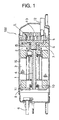
- Fig.1 shows a sectional view of a scroll compressor 100 of the first embodiment of the present invention
- Fig.2 shows an enlarged sectional view of a portion A in Fig.1.
- An airtight container 1 is provided therein with a compressing mechanism 2, an electric motor 3 for driving the compressing mechanism 2, and a crankshaft 4 for transmitting a rotation force of the electric motor 3 to the compressing mechanism 2.
- the compressing mechanism 2 comprises a fixed scroll 5, a circling scroll 6, a bearing 7 and the like. Chip seals 14 are provided in clearances between tip ends of both the fixed scroll 5 and the circling scroll 6 so as to enhance the sealing performance.
- An auxiliary bearing holder 8 is fixed to the airtight container 1, and the airtight container 1 is divided into two, i.e., into a space in which the compressing mechanism 2 exists and a space in which a discharge pipe 9 exists.
- An auxiliary bearing 10 for supporting one end of the crankshaft 4 is mounted to a central portion of the auxiliary bearing holder 8. A portion of a slope of an outer periphery of the auxiliary bearing holder 8 is cut and risen vertically with respect to a wall surface of the airtight container 1 to provide a passage 11 through which refrigerant gas passes.
- the reference number 12 represents an intake pipe and the reference number 13 represents a discharge hole.
- This scroll compressor 100 is an oil-free compressor whose oil amount including residue oil in the motor section and oil required for assembling the scroll mechanism is about 1g in total.
- oil-free compressor since leakage of refrigerant can not be prevented by utilizing an oil seal as in the conventional compressor, it is necessary to make a clearance in the mechanism section small. Therefore, if the fixed scroll 5 and the circling scroll 6 are made of different materials, great sliding abrasion is generated due to a difference in thermal expansion when the compressor is started. Therefore, in the present embodiment, both the fixed scroll 5 and the circling scroll 6 are made of cast iron.
- the operation of the scroll compressor 100 having the above described structure will be explained.
- the crankshaft 4 rotates and as a result, the circling scroll 6 circles with respect to the fixed scroll 5.
- the low pressure refrigerant gas is drawn from the intake pipe 12, compressed in a space formed between the circling scroll 6 and the fixed scroll 5, and discharged into the airtight container 1 from the discharge hole 13.
- the highly pressurized refrigerant gas passes through a gas hole 15 formed in the compressing mechanism 2 and through a groove 16 and the like provided in the electric motor 3 and reaches the auxiliary bearing holder 8.
- the high pressure refrigerant gas passes through the passage 11 provided in the auxiliary bearing holder 8 and discharged out of the scroll compressor 10 from the discharge pipe 9.
- FIG.3 shows its refrigeration cycle.
- the compressor 100, a 4-way valve 18, an outdoor heat exchanger 19, and an expansion device 20 are disposed in an outdoor unit.
- An indoor heat exchanger 21 is disposed in an indoor unit.
- the reference number 22 represents inside/outside connecting pipes.
- This air conditioner could obtain a cooling capacity of 2.5kw by charging 250g of propane in the refrigeration cycle. Further, it took 9 minutes to reach a rated heating capacity at open air temperature of 0°C.
- An air conditioner having the same structure as that in the first embodiment was produced using a scroll compressor which used R22 as refrigerant without using the chip seal. 300g of lubricant was used.
- the chip seals 14 were used at the tip ends of the fixed scroll 5 and the circling scroll 6 in the first embodiment, and the cooling capacity was enhanced about 5% by using the chip seals 14 as compared with a case in which the chip seals were not used. It is difficult, in terms of technique, to partially improving the sliding movement of only the tip ends of the fixed scroll 5 and the circling scroll 6. Therefore, it is possible to reduce the contact areas between the tip ends of the fixed scroll 5 and the circling scroll 6 to enhance the lubrication by employing material having excellent sliding performance for the chip seal.
- the chip seal used in the present embodiment is composed of polyphenylene sulfide (PPS) , carbon fiber and solid-lubricant.
- PPS polyphenylene sulfide
- the solid-lubricant here should be selected from graphite, molybdenum disulfide, tungsten disulfide, boron nitride, polytetrafluoroethylene, polyimide and the like.
- compressor oil is not used in the present embodiment, the initial abrasion at the sliding portions is the biggest problem in view of the reliability. To solve this problem, it is possible to use only a small amount of high-pressure agent directly in the compressor. Further, it is also possible to add the high-pressure agent in the mechanism assembling oil.
- the high-pressure agent it is possible to select from chlorinated paraffin, chlorinated fatty acid ester, mineral oil sulfide, polysulfide, phosfate, phosfite and the like.
- the flammable refrigerant is used in the present embodiment, seizing and spark within the refrigeration cycle are very dangerous. Therefore, to avoid this problem, a small amount of antistatic agent can be used.
- the agent may be directly used in the compressor, or the agent may be added to the mechanism assembling oil.
- the antistatic agent of the present embodiment about 0.5 ⁇ 10 -6 m 3 to 1.0 ⁇ 10 -6 m 3 (0.5 to 1cc) of carboxylic acid amine salt is used.
- this amine salt together with the high-pressure agent, antistatic effect can also be obtained without deteriorating the sliding performance.
- Fig.4 shows a sectional view of a linear compressor 200 of the second embodiment not being a part of the invention
- Fig.5 shows an enlarged sectional view of a portion B in Fig.4.
- An airtight container 23 is provided therein with a compressing mechanism 24 and a linear motor 25 for driving the compressor mechanism 24.
- the compressor mechanism 24 and the linear motor 25 are supported at their opposite sides by supporting springs 26 fixed to the airtight container 23.
- the compressing mechanism 24 comprises a cylinder 27, a piston 28 and the like.
- the piston 28 is fitted into the cylinder 27.
- the piston 28 is provided with a piston ring 29.
- Magnets 30 are fixed to the outer periphery of the piston 28.
- a stator 31 is disposed such as to oppose to the magnets 30. One end of the stator 31 is fixed to the cylinder 27, and the other end thereof is fixed to a resonance spring 32. One end of the piston 28 is supported by a supporting spring 26 and the resonance spring 32. A discharge valve supporting member 33 having a discharge valve therein and a muffler 34 are connected to the cylinder 27. A discharge pipe 35 is disposed spirally from a side of the muffler 34. The piston 28 is provided with an intake hole 36 and an intake valve 37.
- This linear compressor 200 is an oil-free compressor whose oil amount including residue oil in the motor section and oil required for assembling the linear mechanism is about 0.3g in total. Any kind of oil may be used. Both the cylinder 27 and the piston 28 are made of cast iron in the present embodiment also.
- the operation of the linear compressor 200 having the above-described structure will be explained.
- the piston 28 to which the magnets 30 are fixed moves in the opposite direction from the discharge pipe 35 for drawing the refrigerant.
- the low pressure refrigerant is drawn from the intake hole 36 disposed in a side of the piston 28, and is introduced into a space formed by the cylinder 27 and the piston 28 while pushing and opening the intake valve 37 having a damper mechanism.
- the piston 28 is provided with the piston ring 29.
- the cooling capacity was enhanced about 8%.
- a stop ring having the same sealing capacity may be used for the cylinder.
- the ring-like sealing member is composed of polyphenylene sulfide, carbon fiber and solid-lubricant.
- the solid-lubricant here should be selected from graphite, molybdenum disulfide, tungsten disulfide, boron nitride, polytetrafluoroethylene, polyimide and the like.
- the high-pressure and antistatic agent may be used for the linear compressor of the present embodiment as in the first embodiment of the scroll compressor 100.
- the effect obtained by using the high-pressure agent and the antistatic agent was substantially the same as that of the scroll compressor.
- the oil-free compressor by using the oil-free compressor, it is unnecessary to excessively charge the refrigerant in view of the melting amount of the flammable refrigerant into the lubricant and therefore, it is possible to minimize the charging amount of refrigerant. Further, since the refrigerant should not melt into the oil at low temperature unlike the conventional compressor, the starting performance of the apparatus having a refrigeration cycle at the time of heating operation is improved. Further, since the compressor is of the oil-free type, it is easy to cope with disposal problem of electric home appliances.
- the high-pressure agent when a new compressor mechanism section is initially abraded, the high-pressure agent contributes to the sliding surfaces, which can ensure the reliability.
- the fixed scroll and the circling scroll are made of the same material, and the chip seals composed of polyphenylene sulfide, carbon fiber and solid-lubricant are provided on the tip ends of the scrolls. Therefore, it is possible to reduce the sliding load due to the thermal expansion, to enhance the sliding characteristics, and to ensure the reliability of the compressor for a long time.
- the cylinder and the piston of the linear compressor are made of the same material, the load of the sliding surfaces can be reduced. Since the cylinder or the piston is provided with the ring-like seal member made of polyphenylene sulfide, carbon fiber and solid-lubricant, it is possible to reduce the leakage amount of the refrigerant at the time of compression, and to highly improve the efficiency.
Landscapes
- Engineering & Computer Science (AREA)
- Chemical & Material Sciences (AREA)
- Mechanical Engineering (AREA)
- General Engineering & Computer Science (AREA)
- Oil, Petroleum & Natural Gas (AREA)
- General Chemical & Material Sciences (AREA)
- Chemical Kinetics & Catalysis (AREA)
- Organic Chemistry (AREA)
- Physics & Mathematics (AREA)
- Thermal Sciences (AREA)
- Compressor (AREA)
- Applications Or Details Of Rotary Compressors (AREA)
- Lubricants (AREA)
Description
- The present invention relates to apparatus comprising a refrigeration cycle using a flammable refrigerant such as propane (R290), isobutane (R600a) and the like.
- At present, Freon refrigerants that have stable properties and are easy to be handled are used as refrigerants of an apparatus having a refrigeration cycle such as a freezer, a refrigerator, an air conditioner and the like.
- However, although the Freon refrigerants have stable properties and are easy to be handled, it is said that the Freon refrigerants destroy the ozone layer, and since the Freon refrigerants adversely affect the global environment, the use of the Freon refrigerants will be entirely prohibited in the future after a preparatory period of time. Among the Freon refrigerants, hydro fluorocarbon (HFC) refrigerants do not seem to destroy the ozone layer, but they have properties to facilitate the global warming. Especially in Europe where the peoples are concerned about environmental problems, there is a tendency to prohibit the use of this refrigerant also. That is, there is a tendency that the use of the Freon refrigerants that are artificially produced is prohibited, and natural refrigerants such as hydrocarbon are used as in the past. However, such natural refrigerants are flammable, and limited resources must be used effectively, there is a problem that the amount of usage must be controlled.
- The refrigeration cycle of the heat transfer system in the US 5,088,304 contains a rotary compressor of the screw-type. The screw-type compressor consists of a vane and a rotary piston within 'a cylinder. The side surface of the rotary piston has several recesses in the same angular separations as the lobes on the surface of the vane. By forming the recesses of the rotary piston reciprocally to the structure of the vane's lobes the vane can be driven by the rotating piston. Consequently the vane is always in contact with the rotary piston and separates the whole cylinder by this contact in two chambers, one for the suction and the other for the compression of the refrigerant. The screw-type compressor in the US 5,088,304 has typically a lot of sliding surfaces (e.g. the side surfaces of the vane's tip ends being always in contact with the rotating piston; the rotating piston sliding on the wall of the cylinder). Therefore the use of sufficant lubricant for optimizing the sliding conditions is very recommended. An oil-free or an oil-less operation of the screw-type compressor demanding a reduced amount of refrigerant is not possible.
- Thereupon, the present invention has been accomplished by taking notice of refrigerants which melt into lubricant and which do not contribute to heat transfer, and it is an object of the invention to provide an apparatus having a refrigeration cycle in which the amount of refrigerant to be charged in the refrigeration cycle is reduced to enhance the safety. The object is solved by the features of
claim 1. - According to a first aspect not taking part of the present invention, there is provided an apparatus having a refrigeration cycle using a flammable refrigerant, comprising an oil-free compressor, a condenser, an expansion device and an evaporator, wherein an amount of lubricant in the oil-free compressor is equal to or smaller than 3.0·10-6 m3 (3cc).
- The oil-free compressor is a compressor which does not use the lubricant at all or uses a necessary but minimum amount of lubricant less than 3.0·10-6 m3 (3cc), and which can compress and discharge the refrigerant without using a medium of lubricant unlike the conventional technique. Here, about 3.0·10-6 m3 (3cc) or less of lubricant is required when the mechanism section of the compressor is complicated and the mechanism section is to be assembled, or when the high-pressure agent or the antistatic agent is used.
- By using such a compressor, it is unnecessary to excessively charge the refrigerant in view of the melting amount of the flammable refrigerant into the lubricant and therefore, it is possible to reduce the charging amount of refrigerant. Further, since the refrigerant should not excessively melt into the lubricant at a low temperature, the starting performance of the apparatus having a refrigeration cycle at the time of heating operation is improved. Furthermore, since the lubricant is not used, it is possible to eliminate a reduction of flow rate or a stuffed phenomenon in the expansion device due to accumulation of sludge by lubricant conventionally generated as inferior goods. Further, if the disposal problem of electric home appliances is taken into consideration, it is preferable to use the oil-free compressor.
- According to a second aspect not taking part of the invention the lubricant includes a high-pressure agent. With this feature, when a new compressor mechanism section is initially abraded, the high-pressure agent contributes to the sliding surfaces, which can ensure the reliability.
- According to a third aspect, not taking part of the invention, the lubricant includes an antistatic agent. With this feature, it is possible to ensure the safety of the compressor mechanism section and the motor driving portion.
- According to a fourth aspect, in addition to the first aspect, the oil-free compressor is of a scroll type. In the case of the scroll, a load applied to the sliding portion is smaller than that of the rotary and the like. with this feature, it is possible to restrain the sliding surfaces from being reduced even if the lubricant is not used, and to ensure the reliability of the compressor for a long time.
- According to a fifth aspect, in addition to the fourth aspect, the scroll type compressor comprises a fixed scroll and a circling scroll, the fixed scroll and the circling scroll are made of the same material, and are partially provided with a chip seal. With this feature, even when the compressor is started and the temperature rises, since the fixed scroll and the circling scroll are made of the same material, it is possible to reduce the sliding load caused by the thermal expansion, and to ensure the reliability of the compressor for a long time. Further, since the chip seals are provided on the tip ends of the scrolls, the leakage amount of the refrigerant at the time of compression can be reduced, and the efficiency can be enhanced highly.
- According to a sixth aspect, in addition to the fifth aspect, the chip seal is composed of polyphenylene sulfide, carbon fiber and solid-lubricant. With this feature, the sliding performance of the fixed and circling scrolls can be enhanced, the reliability of the compressor can be ensured for a long time.
- According to a seventh aspect not taking part of the invention, the oil-free compressor is of a linear type. With this feature, it is possible to simplify the structure of the compressor itself, to reduce the load of the sliding surfaces, and to sufficiently ensure the reliability of the compressor for a long time even if the lubricant is not used.
- According to an eighth aspect not taking part of the invention, the linear type compressor comprises a cylinder and a piston, the cylinder and the piston are made of the same material, and at least one of the cylinder and the piston is provided with a ring-like seal member. Since the cylinder and the piston are made of the same material, it is possible to reduce the sliding load due to the thermal expansion, and to ensure the reliability of the compressor for a long time. Further, since the compressor mechanism section is provided with the ring-like seal, it is possible to reduce the leakage amount of the refrigerant, and the efficiency can be enhanced highly.
- According to a ninth aspect not taking part of the invention, the ring-like seal member is composed of polyphenylene sulfide, carbon fiber and solid-lubricant. With this feature, the sliding performance between the cylinder and the piston can be enhanced, and the reliability of the compressor can be ensured for a long time.
- According to a tenth aspect, there is provided an apparatus having a refrigeration cycle using a flammable refrigerant, comprising an oil-free compressor, a condenser, an expansion device and an evaporator.
-
- Fig.1 is a sectional view of a scroll compressor according to an embodiment of the present invention;
- Fig.2 is an enlarged sectional view of an essential portion of the scroll compressor according to the embodiment of the invention;
- Fig. 3 is a block diagram of a cycle of an air conditioner according to the embodiment of the invention;
- Fig.4 is a sectional view of a linear compressor according to a second embodiment not being part of the invention; and
- Fig.5 is an enlarged sectional view of an essential portion of the linear compressor according to the second embodiment not being part of the invention.
-
- Embodiments of the present invention will be explained in detail with reference to the drawings below.
- Fig.1 shows a sectional view of a
scroll compressor 100 of the first embodiment of the present invention, and Fig.2 shows an enlarged sectional view of a portion A in Fig.1. - An
airtight container 1 is provided therein with acompressing mechanism 2, anelectric motor 3 for driving thecompressing mechanism 2, and acrankshaft 4 for transmitting a rotation force of theelectric motor 3 to thecompressing mechanism 2. Thecompressing mechanism 2 comprises afixed scroll 5, acircling scroll 6, a bearing 7 and the like.Chip seals 14 are provided in clearances between tip ends of both thefixed scroll 5 and thecircling scroll 6 so as to enhance the sealing performance. Anauxiliary bearing holder 8 is fixed to theairtight container 1, and theairtight container 1 is divided into two, i.e., into a space in which thecompressing mechanism 2 exists and a space in which adischarge pipe 9 exists. An auxiliary bearing 10 for supporting one end of thecrankshaft 4 is mounted to a central portion of theauxiliary bearing holder 8. A portion of a slope of an outer periphery of theauxiliary bearing holder 8 is cut and risen vertically with respect to a wall surface of theairtight container 1 to provide apassage 11 through which refrigerant gas passes. Thereference number 12 represents an intake pipe and thereference number 13 represents a discharge hole. - This
scroll compressor 100 is an oil-free compressor whose oil amount including residue oil in the motor section and oil required for assembling the scroll mechanism is about 1g in total. In the case of oil-free compressor, since leakage of refrigerant can not be prevented by utilizing an oil seal as in the conventional compressor, it is necessary to make a clearance in the mechanism section small. Therefore, if the fixedscroll 5 and the circlingscroll 6 are made of different materials, great sliding abrasion is generated due to a difference in thermal expansion when the compressor is started. Therefore, in the present embodiment, both the fixedscroll 5 and the circlingscroll 6 are made of cast iron. - Next, the operation of the
scroll compressor 100 having the above described structure will be explained. As theelectric motor 3 rotates, thecrankshaft 4 rotates and as a result, the circlingscroll 6 circles with respect to the fixedscroll 5. The low pressure refrigerant gas is drawn from theintake pipe 12, compressed in a space formed between the circlingscroll 6 and the fixedscroll 5, and discharged into theairtight container 1 from thedischarge hole 13. Then, the highly pressurized refrigerant gas passes through agas hole 15 formed in thecompressing mechanism 2 and through agroove 16 and the like provided in theelectric motor 3 and reaches theauxiliary bearing holder 8. Then, the high pressure refrigerant gas passes through thepassage 11 provided in theauxiliary bearing holder 8 and discharged out of thescroll compressor 10 from thedischarge pipe 9. - Using the
scroll compressor 100 structured as described above, an air conditioner using propane as the refrigerant was produced. Fig.3 shows its refrigeration cycle. - The
compressor 100, a 4-way valve 18, anoutdoor heat exchanger 19, and anexpansion device 20 are disposed in an outdoor unit. Anindoor heat exchanger 21 is disposed in an indoor unit. Thereference number 22 represents inside/outside connecting pipes. - This air conditioner could obtain a cooling capacity of 2.5kw by charging 250g of propane in the refrigeration cycle. Further, it took 9 minutes to reach a rated heating capacity at open air temperature of 0°C.
- An air conditioner having the same structure as that in the first embodiment was produced using a scroll compressor which used R22 as refrigerant without using the chip seal. 300g of lubricant was used.
- In this refrigeration cycle, 400g of propane was necessary to obtain a cooling capacity of 2.5kw. It took 14 minutes to reach a rated heating capacity at open air temperature of 0°C.
- As a result of comparison between the first embodiment and the comparative example 1, it was found that an amount of refrigerant (propane) required for obtaining the same capacity could be reduced about 38% by using the oil-free compressor. Further, since the refrigerant did not melt into oil at a low heating temperature at the time of heating operation, a time required for obtaining the rated heating capacity could be shortened.
- The chip seals 14 were used at the tip ends of the fixed
scroll 5 and the circlingscroll 6 in the first embodiment, and the cooling capacity was enhanced about 5% by using the chip seals 14 as compared with a case in which the chip seals were not used. It is difficult, in terms of technique, to partially improving the sliding movement of only the tip ends of the fixedscroll 5 and the circlingscroll 6. Therefore, it is possible to reduce the contact areas between the tip ends of the fixedscroll 5 and the circlingscroll 6 to enhance the lubrication by employing material having excellent sliding performance for the chip seal. - It is preferable that the chip seal used in the present embodiment is composed of polyphenylene sulfide (PPS) , carbon fiber and solid-lubricant. The solid-lubricant here should be selected from graphite, molybdenum disulfide, tungsten disulfide, boron nitride, polytetrafluoroethylene, polyimide and the like.
- Since compressor oil is not used in the present embodiment, the initial abrasion at the sliding portions is the biggest problem in view of the reliability. To solve this problem, it is possible to use only a small amount of high-pressure agent directly in the compressor. Further, it is also possible to add the high-pressure agent in the mechanism assembling oil.
- As the high-pressure agent, it is possible to select from chlorinated paraffin, chlorinated fatty acid ester, mineral oil sulfide, polysulfide, phosfate, phosfite and the like.
- By using 1.0·10-5m3 to 2.0·10-6 m3 (1 to 2cc) of effective high-pressure agent, drape at the time of initial impulse of the mechanism portion can be enhanced.
- Further, since the flammable refrigerant is used in the present embodiment, seizing and spark within the refrigeration cycle are very dangerous. Therefore, to avoid this problem, a small amount of antistatic agent can be used. As the way of using the agent, the agent may be directly used in the compressor, or the agent may be added to the mechanism assembling oil.
- As the antistatic agent of the present embodiment, about 0.5·10-6 m3 to 1.0·10-6 m3 (0.5 to 1cc) of carboxylic acid amine salt is used. By using this amine salt together with the high-pressure agent, antistatic effect can also be obtained without deteriorating the sliding performance.
- Fig.4 shows a sectional view of a
linear compressor 200 of the second embodiment not being a part of the invention, and Fig.5 shows an enlarged sectional view of a portion B in Fig.4. Anairtight container 23 is provided therein with acompressing mechanism 24 and alinear motor 25 for driving thecompressor mechanism 24. Thecompressor mechanism 24 and thelinear motor 25 are supported at their opposite sides by supportingsprings 26 fixed to theairtight container 23. Thecompressing mechanism 24 comprises acylinder 27, apiston 28 and the like. Thepiston 28 is fitted into thecylinder 27. As shown in Fig.5, thepiston 28 is provided with apiston ring 29.Magnets 30 are fixed to the outer periphery of thepiston 28. Astator 31 is disposed such as to oppose to themagnets 30. One end of thestator 31 is fixed to thecylinder 27, and the other end thereof is fixed to a resonance spring 32. One end of thepiston 28 is supported by a supportingspring 26 and the resonance spring 32. A dischargevalve supporting member 33 having a discharge valve therein and amuffler 34 are connected to thecylinder 27. Adischarge pipe 35 is disposed spirally from a side of themuffler 34. Thepiston 28 is provided with an intake hole 36 and anintake valve 37. - This
linear compressor 200 is an oil-free compressor whose oil amount including residue oil in the motor section and oil required for assembling the linear mechanism is about 0.3g in total. Any kind of oil may be used. Both thecylinder 27 and thepiston 28 are made of cast iron in the present embodiment also. - Next, the operation of the
linear compressor 200 having the above-described structure will be explained. By supplying electricity to thestator 31 of thelinear motor 25, thepiston 28 to which themagnets 30 are fixed moves in the opposite direction from thedischarge pipe 35 for drawing the refrigerant. The low pressure refrigerant is drawn from the intake hole 36 disposed in a side of thepiston 28, and is introduced into a space formed by thecylinder 27 and thepiston 28 while pushing and opening theintake valve 37 having a damper mechanism. - If the supply of electricity to the
stator 31 is stopped, energy accumulated in the resonance spring 32 is released, thepiston 28 is pulled back to the original state (in the direction of the discharge pipe 35), and the refrigerant gas is compressed. The compressed refrigerant gas pushes and opens a discharge valve (not shown) provided on the central portion of the discharge valve supporting member, and is discharged into themuffler 34. Then, the high pressure refrigerant gas is discharged out from thelinear compressor 200 through thedischarge pipe 35. At that time, the compression capacity is varied by the number of operations or amount of operation of thepiston 28, and by the number of electricity supply or amount of electricity to the linear motor. Vibration generated by the operation of the compressor such as drawing and discharging operations is controlled by the supportingsprings 26, and vibration and noise of theairtight container 23 itself are reduced. - Using the
linear compressor 200 structured as described above, an air conditioner similar to that of the first embodiment using propane as the refrigerant was produced. This air conditioner could obtain a cooling capacity of 2.5kw by charging 250g of propane in the refrigeration cycle. Further, it took 8 minutes to reach a rated heating capacity at temperature of 0°C. - As a result of comparison between the second embodiment and the comparative example 1, it was found that an amount of refrigerant (propane) required for obtaining the same capacity could be reduced about 38% by using the oil-free compressor. Further, since the refrigerant did not melt into oil at a low heating temperature at the time of heating operation, a time required for obtaining the rated heating capacity could be shortened.
- In the second embodiment, the
piston 28 is provided with thepiston ring 29. By providing thispiston ring 29, the cooling capacity was enhanced about 8%. Although it is possible to reduce the amount of leakage of the refrigerant by reducing the clearance between thecylinder 27 and thepiston 28, if the clearance is too small, it is difficult to fit thepiston 28 into thecylinder 27 in terms of productivity. Therefore, it is possible to reduce the contact areas between thecylinder 27 and thepiston 28 to enhance the lubrication by employing material having excellent sliding performance as for thepiston ring 29. Further, when the compressor is produced and assembled, it is preferable to use a small amount of lubricant so as to facilitate the fitting operation of the piston into the cylinder. Although thepiston ring 29 is used in the second embodiment, a stop ring having the same sealing capacity may be used for the cylinder. - It is preferable that the ring-like sealing member is composed of polyphenylene sulfide, carbon fiber and solid-lubricant. The solid-lubricant here should be selected from graphite, molybdenum disulfide, tungsten disulfide, boron nitride, polytetrafluoroethylene, polyimide and the like.
- The high-pressure and antistatic agent may be used for the linear compressor of the present embodiment as in the first embodiment of the
scroll compressor 100. The effect obtained by using the high-pressure agent and the antistatic agent was substantially the same as that of the scroll compressor. - As is apparent from the above-described embodiments, by using the oil-free compressor, it is unnecessary to excessively charge the refrigerant in view of the melting amount of the flammable refrigerant into the lubricant and therefore, it is possible to minimize the charging amount of refrigerant. Further, since the refrigerant should not melt into the oil at low temperature unlike the conventional compressor, the starting performance of the apparatus having a refrigeration cycle at the time of heating operation is improved. Further, since the compressor is of the oil-free type, it is easy to cope with disposal problem of electric home appliances.
- By using the high-pressure agent, when a new compressor mechanism section is initially abraded, the high-pressure agent contributes to the sliding surfaces, which can ensure the reliability.
- By using the antistatic agent, it is possible to ensure the safety of the compressor mechanism section and the motor driving portion.
- By using the scroll type oil-free compressor, it is possible to restrain the sliding surfaces from being reduced even if the lubricant is not used, and to ensure the reliability of the compressor for a long time.
- Further, the fixed scroll and the circling scroll are made of the same material, and the chip seals composed of polyphenylene sulfide, carbon fiber and solid-lubricant are provided on the tip ends of the scrolls. Therefore, it is possible to reduce the sliding load due to the thermal expansion, to enhance the sliding characteristics, and to ensure the reliability of the compressor for a long time.
- By using the linear type oil-free compressor, it is possible to simplify the structure of the compressor itself, to restrain the sliding surfaces from being reduced even if the lubricant is not used, and to ensure the reliability of the compressor for a long time.
- Further, since the cylinder and the piston of the linear compressor are made of the same material, the load of the sliding surfaces can be reduced. Since the cylinder or the piston is provided with the ring-like seal member made of polyphenylene sulfide, carbon fiber and solid-lubricant, it is possible to reduce the leakage amount of the refrigerant at the time of compression, and to highly improve the efficiency.
Claims (2)
- An apparatus having a refrigeration cycle using a flammable refrigerant, comprising a scroll-type oil-free compressor (100), a condenser (19), and an expansion device (29) and an evaporator (21),
characterised in that
said scroll type compressor (100) comprises a fixed scroll (5) and a circling scroll (6), said fixed scroll (5) and said circling scroll (6) are made of the same material, and are partially provided with a chip seal (14). - An apparatus according to claim 1,
characterised in that
said chip seal (14) is composed of polyphenylene sulfide, carbon fiber and solid-lubricant.
Priority Applications (2)
| Application Number | Priority Date | Filing Date | Title |
|---|---|---|---|
| EP03016716A EP1387132A1 (en) | 1998-02-13 | 1999-02-10 | Apparatus having refrigeration cycle |
| EP03016717A EP1387131A1 (en) | 1998-02-13 | 1999-02-10 | Apparatus having refrigeration cycle |
Applications Claiming Priority (2)
| Application Number | Priority Date | Filing Date | Title |
|---|---|---|---|
| JP10049018A JPH11230628A (en) | 1998-02-13 | 1998-02-13 | Refrigeration equipment |
| JP4901898 | 1998-02-13 |
Related Child Applications (1)
| Application Number | Title | Priority Date | Filing Date |
|---|---|---|---|
| EP03016716A Division EP1387132A1 (en) | 1998-02-13 | 1999-02-10 | Apparatus having refrigeration cycle |
Publications (3)
| Publication Number | Publication Date |
|---|---|
| EP0936422A2 EP0936422A2 (en) | 1999-08-18 |
| EP0936422A3 EP0936422A3 (en) | 2001-02-28 |
| EP0936422B1 true EP0936422B1 (en) | 2004-09-29 |
Family
ID=12819397
Family Applications (3)
| Application Number | Title | Priority Date | Filing Date |
|---|---|---|---|
| EP99102542A Expired - Lifetime EP0936422B1 (en) | 1998-02-13 | 1999-02-10 | Apparatus having refrigeration cycle |
| EP03016716A Withdrawn EP1387132A1 (en) | 1998-02-13 | 1999-02-10 | Apparatus having refrigeration cycle |
| EP03016717A Withdrawn EP1387131A1 (en) | 1998-02-13 | 1999-02-10 | Apparatus having refrigeration cycle |
Family Applications After (2)
| Application Number | Title | Priority Date | Filing Date |
|---|---|---|---|
| EP03016716A Withdrawn EP1387132A1 (en) | 1998-02-13 | 1999-02-10 | Apparatus having refrigeration cycle |
| EP03016717A Withdrawn EP1387131A1 (en) | 1998-02-13 | 1999-02-10 | Apparatus having refrigeration cycle |
Country Status (5)
| Country | Link |
|---|---|
| US (1) | US6082132A (en) |
| EP (3) | EP0936422B1 (en) |
| JP (1) | JPH11230628A (en) |
| DE (1) | DE69920550T2 (en) |
| ES (1) | ES2229565T3 (en) |
Families Citing this family (29)
| Publication number | Priority date | Publication date | Assignee | Title |
|---|---|---|---|---|
| WO1999031444A1 (en) | 1997-12-16 | 1999-06-24 | Matsushita Electric Industrial Co., Ltd. | Airconditioner using inflammable refrigerant |
| US6273688B1 (en) * | 1998-10-13 | 2001-08-14 | Matsushita Electric Industrial Co., Ltd. | Linear compressor |
| JP3899885B2 (en) * | 2001-10-05 | 2007-03-28 | 株式会社日立製作所 | Permanent magnet rotating electric machine |
| US6698214B2 (en) * | 2002-02-22 | 2004-03-02 | Thar Technologies, Inc | Method of refrigeration with enhanced cooling capacity and efficiency |
| US6913413B2 (en) * | 2002-07-24 | 2005-07-05 | Yao-Kun Yang | Coupling lock |
| US7032400B2 (en) * | 2004-03-29 | 2006-04-25 | Hussmann Corporation | Refrigeration unit having a linear compressor |
| JP4337635B2 (en) * | 2004-05-28 | 2009-09-30 | パナソニック株式会社 | Hermetic compressor |
| EP1792084B1 (en) * | 2004-07-13 | 2016-03-30 | Tiax Llc | System and method of refrigeration |
| US20060201175A1 (en) * | 2005-03-10 | 2006-09-14 | Hussmann Corporation | Strategic modular refrigeration system with linear compressors |
| US7213405B2 (en) * | 2005-05-10 | 2007-05-08 | Hussmann Corporation | Two-stage linear compressor |
| US7478539B2 (en) * | 2005-06-24 | 2009-01-20 | Hussmann Corporation | Two-stage linear compressor |
| US7628027B2 (en) * | 2005-07-19 | 2009-12-08 | Hussmann Corporation | Refrigeration system with mechanical subcooling |
| US20080159886A1 (en) * | 2006-12-28 | 2008-07-03 | Lg Electronics Inc. | Compressor and air conditioner having the same |
| JP4738401B2 (en) | 2007-11-28 | 2011-08-03 | 三菱電機株式会社 | Air conditioner |
| GB2457301B (en) | 2008-02-11 | 2013-03-13 | Energetix Pnu Power Ltd | Lubrication of positive displacement expanders |
| JP5535908B2 (en) * | 2008-03-07 | 2014-07-02 | アーケマ・インコーポレイテッド | Halogenated alkene refrigerant compositions with improved oil return and methods using them |
| JP2009222032A (en) * | 2008-03-18 | 2009-10-01 | Daikin Ind Ltd | Refrigerating apparatus |
| CN102080658B (en) * | 2009-11-26 | 2012-08-22 | 广东美芝制冷设备有限公司 | Closed type rolling rotor compressor |
| CN102080657B (en) * | 2009-11-26 | 2012-08-22 | 广东美芝制冷设备有限公司 | Enclosed rolling rotor compressor |
| CN113897181A (en) | 2013-01-25 | 2022-01-07 | 特灵国际有限公司 | Refrigerant additives and compositions |
| WO2016160873A1 (en) | 2015-03-30 | 2016-10-06 | Carrier Corporation | Low-oil refrigerants and vapor compression systems |
| KR102238332B1 (en) * | 2016-04-19 | 2021-04-09 | 엘지전자 주식회사 | Linear compressor |
| CN106091188A (en) * | 2016-06-12 | 2016-11-09 | 重庆美的通用制冷设备有限公司 | Refrigeration unit |
| CN107816823B (en) | 2016-09-14 | 2021-11-23 | 开利公司 | Refrigeration system and lubrication method thereof |
| US11292987B2 (en) | 2017-03-29 | 2022-04-05 | Carrier Corporation | Active filter for oil-free refrigerant compressor |
| EP3842708B1 (en) | 2018-08-20 | 2025-09-17 | Daikin Industries, Ltd. | Refrigeration cycle device |
| US11300328B2 (en) | 2018-12-19 | 2022-04-12 | Emerson Climate Technologies, Inc. | Oil control for climate-control system |
| WO2020132352A1 (en) | 2018-12-19 | 2020-06-25 | Emerson Climate Technologies, Inc. | Oil control for climate-control system |
| JP7393680B2 (en) * | 2022-02-22 | 2023-12-07 | ダイキン工業株式会社 | Refrigeration cycle equipment |
Citations (1)
| Publication number | Priority date | Publication date | Assignee | Title |
|---|---|---|---|---|
| GB1119488A (en) * | 1966-11-16 | 1968-07-10 | Vilter Manufacturing Corp | Oil free refrigerant compressor |
Family Cites Families (13)
| Publication number | Priority date | Publication date | Assignee | Title |
|---|---|---|---|---|
| JPH0733828B2 (en) * | 1986-12-29 | 1995-04-12 | 株式会社日立製作所 | Scroll type vacuum pump |
| US5051066A (en) * | 1989-09-25 | 1991-09-24 | Lucas Timothy S | Gas compression by pulse amplification |
| US5088304A (en) * | 1990-10-15 | 1992-02-18 | Schlichtig Ralph C | Heat transfer system with recovery means |
| JP2966575B2 (en) * | 1991-05-29 | 1999-10-25 | 株式会社日立製作所 | Oil-free scroll compressor |
| US5318412A (en) * | 1992-04-03 | 1994-06-07 | General Electric Company | Flexible suspension for an oil free linear motor compressor |
| US5458798A (en) * | 1993-02-05 | 1995-10-17 | E. I. Du Pont De Nemours And Company | Azeotropic and azeotrope-like compositions of a hydrofluorocarbon and a hydrocarbon |
| IL109967A (en) * | 1993-06-15 | 1997-07-13 | Multistack Int Ltd | Compressor |
| JPH07305083A (en) * | 1994-05-10 | 1995-11-21 | Hitachi Ltd | Lubricating oil composition and working medium containing the lubricating oil composition |
| US5690480A (en) * | 1995-02-20 | 1997-11-25 | Hitachi, Ltd. | Scroll compressor with cooling holes in orbiting scroll |
| US6151901A (en) * | 1995-10-12 | 2000-11-28 | Cryogen, Inc. | Miniature mixed gas refrigeration system |
| US5957667A (en) * | 1997-05-23 | 1999-09-28 | Ballard Generation Systems Inc. | Oilless compressor with a pressurizable crankcase and motor containment vessel |
| JP2000097171A (en) * | 1998-09-21 | 2000-04-04 | Hitachi Ltd | Scroll compressor and refrigeration system using the same |
| US6273688B1 (en) * | 1998-10-13 | 2001-08-14 | Matsushita Electric Industrial Co., Ltd. | Linear compressor |
-
1998
- 1998-02-13 JP JP10049018A patent/JPH11230628A/en active Pending
-
1999
- 1999-02-10 EP EP99102542A patent/EP0936422B1/en not_active Expired - Lifetime
- 1999-02-10 EP EP03016716A patent/EP1387132A1/en not_active Withdrawn
- 1999-02-10 ES ES99102542T patent/ES2229565T3/en not_active Expired - Lifetime
- 1999-02-10 DE DE69920550T patent/DE69920550T2/en not_active Expired - Lifetime
- 1999-02-10 EP EP03016717A patent/EP1387131A1/en not_active Withdrawn
- 1999-02-11 US US09/248,276 patent/US6082132A/en not_active Expired - Fee Related
Patent Citations (1)
| Publication number | Priority date | Publication date | Assignee | Title |
|---|---|---|---|---|
| GB1119488A (en) * | 1966-11-16 | 1968-07-10 | Vilter Manufacturing Corp | Oil free refrigerant compressor |
Also Published As
| Publication number | Publication date |
|---|---|
| JPH11230628A (en) | 1999-08-27 |
| EP1387132A1 (en) | 2004-02-04 |
| EP1387131A1 (en) | 2004-02-04 |
| EP0936422A3 (en) | 2001-02-28 |
| US6082132A (en) | 2000-07-04 |
| DE69920550T2 (en) | 2006-03-09 |
| DE69920550D1 (en) | 2004-11-04 |
| EP0936422A2 (en) | 1999-08-18 |
| ES2229565T3 (en) | 2005-04-16 |
Similar Documents
| Publication | Publication Date | Title |
|---|---|---|
| US6082132A (en) | Apparatus having refrigeration cycle | |
| JP3473776B2 (en) | Hermetic compressor | |
| US6575716B1 (en) | Linear compressor | |
| KR100224325B1 (en) | Scroll compressor and the manufacturing method | |
| US6210130B1 (en) | Rotary compressor, refrigerating cycle using the compressor, and refrigerator using the compressor | |
| CN105736372B (en) | Rotary compressor | |
| US6385995B1 (en) | Apparatus having a refrigeration circuit | |
| CN217327674U (en) | Magnetic suspension screw type refrigeration compressor | |
| CN113236562A (en) | Magnetic suspension screw type refrigeration compressor | |
| JPH06264881A (en) | Rotary compressor | |
| JP4316048B2 (en) | Refrigerant circulation system | |
| JP3301836B2 (en) | Internal high pressure compressor | |
| CN222950065U (en) | Compressor and air conditioner | |
| CN109996901B (en) | Oxide film, sliding member having the same formed thereon, and apparatus having the sliding member | |
| CN222950066U (en) | Compressor and air conditioner | |
| JP2021080926A (en) | Hermetic refrigerant compressor and freezing device using the same | |
| CN223152226U (en) | Compressor and multi-split air conditioner | |
| CN223035251U (en) | Compressor and air conditioner | |
| CN222991717U (en) | Compressor and air conditioner | |
| JPH1113667A (en) | Rotary compressor and refrigerant recovery machine | |
| JP5469612B2 (en) | Rotary fluid machinery | |
| Sjoholm | Different operational modes for refrigeration twin-screw compressors | |
| JPH07180678A (en) | Rotary compressor | |
| JP2000105005A (en) | Rotary compressor | |
| JPH07259768A (en) | Rotary compressor |
Legal Events
| Date | Code | Title | Description |
|---|---|---|---|
| PUAI | Public reference made under article 153(3) epc to a published international application that has entered the european phase |
Free format text: ORIGINAL CODE: 0009012 |
|
| AK | Designated contracting states |
Kind code of ref document: A2 Designated state(s): DE ES GR IT SE |
|
| AX | Request for extension of the european patent |
Free format text: AL;LT;LV;MK;RO;SI |
|
| PUAL | Search report despatched |
Free format text: ORIGINAL CODE: 0009013 |
|
| AK | Designated contracting states |
Kind code of ref document: A3 Designated state(s): AT BE CH CY DE DK ES FI FR GB GR IE IT LI LU MC NL PT SE |
|
| AX | Request for extension of the european patent |
Free format text: AL;LT;LV;MK;RO;SI |
|
| 17P | Request for examination filed |
Effective date: 20010322 |
|
| AKX | Designation fees paid |
Free format text: DE ES GR IT SE |
|
| 17Q | First examination report despatched |
Effective date: 20020513 |
|
| GRAP | Despatch of communication of intention to grant a patent |
Free format text: ORIGINAL CODE: EPIDOSNIGR1 |
|
| GRAS | Grant fee paid |
Free format text: ORIGINAL CODE: EPIDOSNIGR3 |
|
| GRAA | (expected) grant |
Free format text: ORIGINAL CODE: 0009210 |
|
| AK | Designated contracting states |
Kind code of ref document: B1 Designated state(s): DE ES GR IT SE |
|
| REF | Corresponds to: |
Ref document number: 69920550 Country of ref document: DE Date of ref document: 20041104 Kind code of ref document: P |
|
| PG25 | Lapsed in a contracting state [announced via postgrant information from national office to epo] |
Ref country code: SE Free format text: LAPSE BECAUSE OF FAILURE TO SUBMIT A TRANSLATION OF THE DESCRIPTION OR TO PAY THE FEE WITHIN THE PRESCRIBED TIME-LIMIT Effective date: 20041229 |
|
| REG | Reference to a national code |
Ref country code: GR Ref legal event code: EP Ref document number: 20040404211 Country of ref document: GR |
|
| REG | Reference to a national code |
Ref country code: ES Ref legal event code: FG2A Ref document number: 2229565 Country of ref document: ES Kind code of ref document: T3 |
|
| PLBE | No opposition filed within time limit |
Free format text: ORIGINAL CODE: 0009261 |
|
| STAA | Information on the status of an ep patent application or granted ep patent |
Free format text: STATUS: NO OPPOSITION FILED WITHIN TIME LIMIT |
|
| 26N | No opposition filed |
Effective date: 20050630 |
|
| PGFP | Annual fee paid to national office [announced via postgrant information from national office to epo] |
Ref country code: DE Payment date: 20150203 Year of fee payment: 17 Ref country code: IT Payment date: 20150218 Year of fee payment: 17 Ref country code: ES Payment date: 20150113 Year of fee payment: 17 |
|
| PGFP | Annual fee paid to national office [announced via postgrant information from national office to epo] |
Ref country code: SE Payment date: 20150212 Year of fee payment: 17 Ref country code: GR Payment date: 20150114 Year of fee payment: 17 |
|
| REG | Reference to a national code |
Ref country code: DE Ref legal event code: R119 Ref document number: 69920550 Country of ref document: DE |
|
| REG | Reference to a national code |
Ref country code: SE Ref legal event code: EUG |
|
| PG25 | Lapsed in a contracting state [announced via postgrant information from national office to epo] |
Ref country code: GR Free format text: LAPSE BECAUSE OF NON-PAYMENT OF DUE FEES Effective date: 20160905 Ref country code: SE Free format text: LAPSE BECAUSE OF NON-PAYMENT OF DUE FEES Effective date: 20160211 |
|
| PG25 | Lapsed in a contracting state [announced via postgrant information from national office to epo] |
Ref country code: IT Free format text: LAPSE BECAUSE OF NON-PAYMENT OF DUE FEES Effective date: 20160210 |
|
| PG25 | Lapsed in a contracting state [announced via postgrant information from national office to epo] |
Ref country code: DE Free format text: LAPSE BECAUSE OF NON-PAYMENT OF DUE FEES Effective date: 20160901 |
|
| REG | Reference to a national code |
Ref country code: GR Ref legal event code: ML Ref document number: 20040404211 Country of ref document: GR Effective date: 20160905 |
|
| PG25 | Lapsed in a contracting state [announced via postgrant information from national office to epo] |
Ref country code: ES Free format text: LAPSE BECAUSE OF NON-PAYMENT OF DUE FEES Effective date: 20160211 |