EP0936357A2 - Compressor bleed valve - Google Patents
Compressor bleed valve Download PDFInfo
- Publication number
- EP0936357A2 EP0936357A2 EP99301044A EP99301044A EP0936357A2 EP 0936357 A2 EP0936357 A2 EP 0936357A2 EP 99301044 A EP99301044 A EP 99301044A EP 99301044 A EP99301044 A EP 99301044A EP 0936357 A2 EP0936357 A2 EP 0936357A2
- Authority
- EP
- European Patent Office
- Prior art keywords
- piston
- flow path
- fluid flow
- bleed valve
- compressor
- Prior art date
- Legal status (The legal status is an assumption and is not a legal conclusion. Google has not performed a legal analysis and makes no representation as to the accuracy of the status listed.)
- Granted
Links
Images


Classifications
-
- F—MECHANICAL ENGINEERING; LIGHTING; HEATING; WEAPONS; BLASTING
- F01—MACHINES OR ENGINES IN GENERAL; ENGINE PLANTS IN GENERAL; STEAM ENGINES
- F01D—NON-POSITIVE DISPLACEMENT MACHINES OR ENGINES, e.g. STEAM TURBINES
- F01D17/00—Regulating or controlling by varying flow
- F01D17/10—Final actuators
- F01D17/105—Final actuators by passing part of the fluid
-
- F—MECHANICAL ENGINEERING; LIGHTING; HEATING; WEAPONS; BLASTING
- F04—POSITIVE - DISPLACEMENT MACHINES FOR LIQUIDS; PUMPS FOR LIQUIDS OR ELASTIC FLUIDS
- F04D—NON-POSITIVE-DISPLACEMENT PUMPS
- F04D27/00—Control, e.g. regulation, of pumps, pumping installations or pumping systems specially adapted for elastic fluids
- F04D27/02—Surge control
- F04D27/0207—Surge control by bleeding, bypassing or recycling fluids
- F04D27/0215—Arrangements therefor, e.g. bleed or by-pass valves
-
- F—MECHANICAL ENGINEERING; LIGHTING; HEATING; WEAPONS; BLASTING
- F04—POSITIVE - DISPLACEMENT MACHINES FOR LIQUIDS; PUMPS FOR LIQUIDS OR ELASTIC FLUIDS
- F04D—NON-POSITIVE-DISPLACEMENT PUMPS
- F04D27/00—Control, e.g. regulation, of pumps, pumping installations or pumping systems specially adapted for elastic fluids
- F04D27/02—Surge control
- F04D27/0207—Surge control by bleeding, bypassing or recycling fluids
- F04D27/023—Details or means for fluid extraction
Definitions
- the present invention relates to gas turbine engines, and particularly to a compressor bleed valve for improving the control of surge in such engines.
- a pneumatic bleed valve is also described in U.S. Patent 5,477,673, Blais et al., issued December 26, 1995.
- This patent describes a bleed valve in the form of a piston extending radially through a bypass flow path, and operable to bleed compressor air into the bypass flow path when the piston type valve is open.
- the valve may be closed when air from a source downstream of the compressor impeller is fed to the head of the piston and such air is at a higher pressure than air from a downstream stage of the compressor.
- the pneumatic force to close the valve acts against a spring normally urging the valve to an open position.
- the bleed valve moves from an open to a closed position gradually. If during this transition the opening becomes too small, the engine may be in a surge condition.
- a gas turbine engine including a compressor with an axial fluid flow path, a bypass fluid flow path concentric with the compressor fluid flow path, a bleed valve in fluid communication with the compressor fluid flow path and the bypass fluid flow path whereby the bleed valve comprises a piston extending radially, with a piston head radially remote from the compressor fluid flow path, a pneumatic chamber surrounding a portion of the piston head and means for introducing compressed fluid into said chamber, the piston including a valving means and a rigid member extending between the piston head and the valving means whereby the piston is effective to open or close the communication between the compressor fluid flow path, the improvement comprising a precompressed spring associated with the piston to normally urge the piston radially outwardly relative to the compressor fluid flow, the arrangement being such that the pneumatic pressure in the chamber surrounding the piston head must overcome the precompressed spring in order to close said valving means and the precompression spring is such that the closing schedule of the bleed valve will avoid the surge conditions of the engine.
- a bleed valve in fluid communication with the compressor fluid flow path and the bypass fluid flow path whereby a piston extends radially of the valve and includes a piston head radially remote from the compressor fluid flow path, a pneumatic chamber surrounding a portion of the piston head and means for introducing compressed fluid into said chamber, the piston including a valving member and a rigid member connecting the piston head to the valving means whereby the piston is effective to open or close the communication between the compressor flow path and the bypass flow path, and a precompressed spring associated with the piston to normally urge the piston radially outwardly relative to the compressor fluid flow path to a valve open position whereby to close the valve, the pneumatic pressure in the chamber surrounding the piston head must overcome the precompressed spring.
- the spring is precompressed to 40 lbs.
- a bleed valve 10 is shown mounted in a compressor section 14 of a gas turbine engine having a bypass fluid flow path 12.
- the bleed valve 10, shown in Fig. 1 is according to U.S. Patent 5,477,673, Blais et al., which is herewith incorporated by reference.
- the compressor section includes a fluid flow path 16 which is somewhat concentric with the bypass fluid flow path 12.
- the compressor includes a downstream compressor stage outlet port 22 in shroud 18, adjacent the centrifugal impeller 24.
- the bleed valve 10 is a piston type bleed valve having a closed casing with a piston 26 and a guide rod 28 fixed to the upper chamber housing 27 which defines a closed chamber 32.
- a piston head 34 slides within the chamber 32 in sealing relationship.
- the piston 26 includes a sleeve 30 and 30a which slides on the rod 28.
- the rod 28 is connected to the chamber housing 27 by means of a nut 31.
- the rod 28 is connected at its other end to the valve chamber housing 52 by means of nut 29.
- the valve chamber 52 is in the form of an open basket with openings 42.
- the valving element 36 includes a frusto-conical surface 37 and a partial cylindrical skirt 38 defining an opening 39 which corresponds with opening 40 in the bypass fluid flow inner wall 20.
- the bleed valve when in an open position as shown in Fig. 1, allows bleed air from the downstream portion of the compressor to pass through openings 42 and through opening 40 to the bypass fluid flow path 12 downstream of the bleed valve 10.
- the spring 44 normally urges the valve to its open position, as shown in Fig. 1, and the valve is closed pneumatically as described in the above United States patent.
- valve under the pneumatic pressure from a source downstream of the compressor impeller, as described in the above-mentioned patent, will prematurely close the valve against the spring 44 while the engine is still vulnerable to a surge condition.
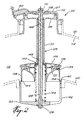
- a bleed valve in accordance with the present invention, is shown and identified as 110. All of the reference numerals which correspond to reference numerals in Fig. 1 have been raised by 100.
- the bleed valve 110 of Figs. 2 and 3 is shown in cross-section in a radial plane, that is, at 90° to the cross-section of Fig. 1.
- the bleed valve 110 includes an upper casing 127 defining a piston chamber 132 communicating with an inlet 150.
- Bleed valve 110 is a piston-type bleed valve and includes a piston 126 which includes the sleeve 130 having bushings 148 sliding on rod 128.
- Rod 128 is fixed at the casing 127 by means of nut 131.
- rod 128 mounts a valve housing 152 in the form of an open basket which defines a valve seat 154 adjacent the inner wall 120 of the bypass fluid flow path 112.
- the sleeve 130 mounts a piston head 134 which is adapted to slide in sealing engagement within the chamber 132.
- At the other end of the sleeve 130 is an aerodynamic cap 146 to which is connected a valving element 136.
- the valving element 136 includes a frusto-conical surface surrounded partially by a skirt 138 which is adapted to slide within the basket 152.
- the valving element 136 defines an annular spring recess 143 which houses a coil spring 144.
- the skirt 138 defines an opening 139 in the downstream side of the valving element 136 (although the opening 139 is shown to one side in Figs. 2 and 3 for the purposes of illustration only).
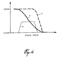
- curve N represents the bleed valve as shown in Fig. 1 of the spring 44.
- curve N as it is closing, passes through the so-called surge bucket S.
- surge bucket S As the valve 36 is being closed, it is difficult to control the valve opening.
- the curve P shown in Fig. 4 represents the schedule for closing valve 136 using a precompressed spring 144.
- a preferred spring rating will include a precompression of 40 lbs. when the valve is completely opened, although a precompression of 20 lbs. should be sufficient to clear the surge bucket 144. This compares to zero compression in terms of spring 44 in Fig. 1 when the valve is completely opened. It is anticipated that the spring could also be precompressed to 50 lbs. It is noted that when the valve 36 is closed, the spring 144 is compressed to 60 lbs. which is similar to the spring 44 in Fig. 1.
Abstract
Description
- The present invention relates to gas turbine engines, and particularly to a compressor bleed valve for improving the control of surge in such engines.
- U.S. Patent 3,809,490, Harner, issued May 7, 1974, describes the on-going problem of trying to avoid surge in gas turbine engines. The solution proposed over the years has been the provision of bleed valves to bleed off compressor air at different stages of the compressor. Thus, controls, mechanical or pneumatic, are provided for anticipating a surge condition by causing the valves to be opened to thereby bleed off air before a surge condition is to happen. Thus, in high power requirement conditions, the bleed valves are maintained closed, but during low power, the bleed valves are opened.
- A pneumatic bleed valve is also described in U.S. Patent 5,477,673, Blais et al., issued December 26, 1995. This patent describes a bleed valve in the form of a piston extending radially through a bypass flow path, and operable to bleed compressor air into the bypass flow path when the piston type valve is open. The valve may be closed when air from a source downstream of the compressor impeller is fed to the head of the piston and such air is at a higher pressure than air from a downstream stage of the compressor. The pneumatic force to close the valve acts against a spring normally urging the valve to an open position.
- As the engine speed changes from low to high, the bleed valve moves from an open to a closed position gradually. If during this transition the opening becomes too small, the engine may be in a surge condition.
- It is an object of the invention to seek to provide an improved pneumatic valve of the type described in U.S. Patent 5,477,673 that includes a means for maintaining the bleed valve open with a larger bleed opening during gradual closing of the bleed valve during pneumatic control of the valve.
- According to the invention there is provided in a gas turbine engine including a compressor with an axial fluid flow path, a bypass fluid flow path concentric with the compressor fluid flow path, a bleed valve in fluid communication with the compressor fluid flow path and the bypass fluid flow path whereby the bleed valve comprises a piston extending radially, with a piston head radially remote from the compressor fluid flow path, a pneumatic chamber surrounding a portion of the piston head and means for introducing compressed fluid into said chamber, the piston including a valving means and a rigid member extending between the piston head and the valving means whereby the piston is effective to open or close the communication between the compressor fluid flow path, the improvement comprising a precompressed spring associated with the piston to normally urge the piston radially outwardly relative to the compressor fluid flow, the arrangement being such that the pneumatic pressure in the chamber surrounding the piston head must overcome the precompressed spring in order to close said valving means and the precompression spring is such that the closing schedule of the bleed valve will avoid the surge conditions of the engine.
- Thus in a gas turbine engine including a compressor and a bypass fluid flow path concentric with the compressor fluid flow path, there is a bleed valve in fluid communication with the compressor fluid flow path and the bypass fluid flow path whereby a piston extends radially of the valve and includes a piston head radially remote from the compressor fluid flow path, a pneumatic chamber surrounding a portion of the piston head and means for introducing compressed fluid into said chamber, the piston including a valving member and a rigid member connecting the piston head to the valving means whereby the piston is effective to open or close the communication between the compressor flow path and the bypass flow path, and a precompressed spring associated with the piston to normally urge the piston radially outwardly relative to the compressor fluid flow path to a valve open position whereby to close the valve, the pneumatic pressure in the chamber surrounding the piston head must overcome the precompressed spring.
- Thus using the invention it is possible to provide a precompressed spring on the piston forming the operable portion of the valve.
- In a more specific embodiment of the present invention, the spring is precompressed to 40 lbs.
- It has been found that by precompressing the spring in the bleed valve described in U.S. Patent 5,477,673, significant improvement can be obtained in avoiding possible engine surging by maintaining the bleed valve open longer and especially maintaining a larger opening of the bleed valve until the surge conditions are passed and the valve can definitely close.
- Having thus generally described the nature of the invention, reference will now be made to the accompanying drawings, showing by way of illustration, a preferred embodiment thereof, and in which:
- Fig. 1 is an axial cross-section of a compressor portion of a gas turbine engine shown in dotted lines and illustrating in cross-section a bleed valve in accordance with the prior art in an open position;
- Fig. 2 is a cross-section taken in a vertical plane of the bleed valve in accordance with the present invention in an open position;
- Fig. 3 is a cross-section, similar to Fig. 2, showing the bleed valve of the present invention in a closed position; and
- Fig. 4 is a graph illustrating the operating schedule of the bleed valve in accordance with the present invention compared with a prior art bleed valve.
-
- Referring now to the drawings and particularly to Fig. 1, a
bleed valve 10 is shown mounted in acompressor section 14 of a gas turbine engine having a bypassfluid flow path 12. The bleedvalve 10, shown in Fig. 1, is according to U.S. Patent 5,477,673, Blais et al., which is herewith incorporated by reference. As shown in Fig. 1, the compressor section includes afluid flow path 16 which is somewhat concentric with the bypassfluid flow path 12. The compressor includes a downstream compressorstage outlet port 22 in shroud 18, adjacent thecentrifugal impeller 24. - The bleed
valve 10 is a piston type bleed valve having a closed casing with a piston 26 and aguide rod 28 fixed to the upper chamber housing 27 which defines a closed chamber 32. A piston head 34 slides within the chamber 32 in sealing relationship. The piston 26 includes a sleeve 30 and 30a which slides on therod 28. Therod 28 is connected to the chamber housing 27 by means of anut 31. Therod 28 is connected at its other end to thevalve chamber housing 52 by means of nut 29. Thevalve chamber 52 is in the form of an open basket withopenings 42. Thevalving element 36 includes a frusto-conical surface 37 and a partialcylindrical skirt 38 defining an opening 39 which corresponds with opening 40 in the bypass fluid flowinner wall 20. - As described in U.S. Patent 5,477,673, the bleed valve, when in an open position as shown in Fig. 1, allows bleed air from the downstream portion of the compressor to pass through
openings 42 and through opening 40 to the bypassfluid flow path 12 downstream of the bleedvalve 10. Thespring 44 normally urges the valve to its open position, as shown in Fig. 1, and the valve is closed pneumatically as described in the above United States patent. - It has been found that the valve, under the pneumatic pressure from a source downstream of the compressor impeller, as described in the above-mentioned patent, will prematurely close the valve against the
spring 44 while the engine is still vulnerable to a surge condition. - Referring now to Figs. 2 and 3, the bleed valve, in accordance with the present invention, is shown and identified as 110. All of the reference numerals which correspond to reference numerals in Fig. 1 have been raised by 100.
- The bleed
valve 110 of Figs. 2 and 3 is shown in cross-section in a radial plane, that is, at 90° to the cross-section of Fig. 1. - The
bleed valve 110 includes anupper casing 127 defining apiston chamber 132 communicating with aninlet 150.Bleed valve 110 is a piston-type bleed valve and includes apiston 126 which includes thesleeve 130 havingbushings 148 sliding onrod 128.Rod 128 is fixed at thecasing 127 by means ofnut 131. At the other end,rod 128 mounts avalve housing 152 in the form of an open basket which defines avalve seat 154 adjacent theinner wall 120 of the bypassfluid flow path 112. - The
sleeve 130 mounts apiston head 134 which is adapted to slide in sealing engagement within thechamber 132. At the other end of thesleeve 130 is anaerodynamic cap 146 to which is connected avalving element 136. Thevalving element 136 includes a frusto-conical surface surrounded partially by askirt 138 which is adapted to slide within thebasket 152. Thevalving element 136 defines anannular spring recess 143 which houses acoil spring 144. Theskirt 138 defines anopening 139 in the downstream side of the valving element 136 (although theopening 139 is shown to one side in Figs. 2 and 3 for the purposes of illustration only). - Referring to Fig. 4, the curve N represents the bleed valve as shown in Fig. 1 of the
spring 44. Thus, it can be seen that curve N, as it is closing, passes through the so-called surge bucket S. As thevalve 36 is being closed, it is difficult to control the valve opening. - It has been found, however, that by precompressing the
spring 144, as shown in Figs. 2 and 3, the airpressure entering inlet 150 in Fig. 2 required to urge thepiston head 134 and thus thepiston 126 to close against thevalve seat 154 will need to be higher since theprecompressed spring 144 offers more resistance. Since the necessary force required to overcome thespring 144 will be greater, the valve will remain open longer and will naturally be larger since the valving member will not readily close the opening unless a larger force is applied. - The curve P shown in Fig. 4 represents the schedule for
closing valve 136 using aprecompressed spring 144. - It has been found that a preferred spring rating will include a precompression of 40 lbs. when the valve is completely opened, although a precompression of 20 lbs. should be sufficient to clear the
surge bucket 144. This compares to zero compression in terms ofspring 44 in Fig. 1 when the valve is completely opened. It is anticipated that the spring could also be precompressed to 50 lbs. It is noted that when thevalve 36 is closed, thespring 144 is compressed to 60 lbs. which is similar to thespring 44 in Fig. 1.
Claims (5)
- In a gas turbine engine including a compressor with an axial fluid flow path, a bypass fluid flow path concentric with the compressor fluid flow path, a bleed valve in fluid communication with the compressor fluid flow path and the bypass fluid flow path whereby the bleed valve comprises a piston extending radially, with a piston head radially remote from the compressor fluid flow path, a pneumatic chamber surrounding a portion of the piston head and means for introducing compressed fluid into said chamber, the piston including a valving means and a rigid member extending between the piston head and the valving means whereby the piston is effective to open or close the communication between the compressor fluid flow path, the improvement comprising a precompressed spring associated with the piston to normally urge the piston radially outwardly relative to the compressor fluid flow, the arrangement being such that the pneumatic pressure in the chamber surrounding the piston head must overcome the precompressed spring in order to close said valving means and the precompression spring is such that the closing schedule of the bleed valve will avoid the surge conditions of the engine.
- The bleed valve according to Claim 1, characterised in that the precompressed spring is a coil spring precompressed to between 20 and 50 lbs.
- The bleed valve according to Claim 2, characterised in that the spring is precompressed to 40 lbs.
- The bleed valve according to any preceding claim, characterised in that the bleed valve includes a casing defining the pneumatic chamber mounted to the outer shroud of the bypass fluid flow path and a valving means housing is mounted to the other end of a rod fixed to the chamber casing whereby the valving means housing is mounted to the inner wall of the bypass fluid flow path, the piston includes the piston head and an elongated sleeve connecting the piston head to the valving element such that the sleeve slides on the rod between a valve opened position and a valve closed position and the precompressed spring is mounted in the valving element housing between the valving element and the housing so as to urge the piston and the valving element to an open position.
- The bleed valve according to Claim 4, characterised in that the spring is precompressed to 40 lbs.
Applications Claiming Priority (4)
| Application Number | Priority Date | Filing Date | Title |
|---|---|---|---|
| US09/023,217 US6122905A (en) | 1998-02-13 | 1998-02-13 | Compressor bleed valve |
| CA002229352A CA2229352C (en) | 1998-02-13 | 1998-02-13 | Compressor bleed valve |
| CA2229352 | 1998-02-13 | ||
| US23217 | 1998-02-13 |
Publications (3)
| Publication Number | Publication Date |
|---|---|
| EP0936357A2 true EP0936357A2 (en) | 1999-08-18 |
| EP0936357A3 EP0936357A3 (en) | 2001-01-10 |
| EP0936357B1 EP0936357B1 (en) | 2003-11-05 |
Family
ID=25680035
Family Applications (1)
| Application Number | Title | Priority Date | Filing Date |
|---|---|---|---|
| EP99301044A Expired - Lifetime EP0936357B1 (en) | 1998-02-13 | 1999-02-12 | Gas turbine engine |
Country Status (3)
| Country | Link |
|---|---|
| EP (1) | EP0936357B1 (en) |
| JP (1) | JPH11287133A (en) |
| DE (1) | DE69912488T2 (en) |
Cited By (4)
| Publication number | Priority date | Publication date | Assignee | Title |
|---|---|---|---|---|
| WO2005010414A1 (en) * | 2003-07-22 | 2005-02-03 | Honeywell International Inc. | Bleed valve system |
| EP1300567A3 (en) * | 2001-10-04 | 2006-11-02 | United Technologies Corporation | Bleed deflector for a gas turbine |
| CN112361061A (en) * | 2020-11-30 | 2021-02-12 | 中国船舶重工集团公司第七0三研究所 | Be applied to gas turbine's bleed valve of taking position feedback |
| CN113606042A (en) * | 2021-08-17 | 2021-11-05 | 中国航发贵阳发动机设计研究所 | Mounting structure of automatically-locked starting valve device on aircraft engine |
Citations (2)
| Publication number | Priority date | Publication date | Assignee | Title |
|---|---|---|---|---|
| US3809490A (en) | 1973-05-02 | 1974-05-07 | United Aircraft Corp | Compressor surge sensor |
| US5477673A (en) | 1994-08-10 | 1995-12-26 | Pratt & Whitney Canada Inc. | Handling bleed valve |
Family Cites Families (3)
| Publication number | Priority date | Publication date | Assignee | Title |
|---|---|---|---|---|
| DE2247400C2 (en) * | 1972-09-27 | 1975-01-16 | Motoren- Und Turbinen-Union Muenchen Gmbh, 8000 Muenchen | Device for blowing off compressed air from a compressor of a gas turbine jet engine |
| DE2529422C3 (en) * | 1975-07-02 | 1980-12-04 | Alfons Schwarte Gmbh, 4730 Ahlen | Device for separating air when taking milk from milk containers into milk collecting containers, in particular milk collecting trucks |
| US4574585A (en) * | 1985-02-08 | 1986-03-11 | General Motors Corporation | Compressor bleed valve |
-
1999
- 1999-02-12 DE DE69912488T patent/DE69912488T2/en not_active Expired - Lifetime
- 1999-02-12 EP EP99301044A patent/EP0936357B1/en not_active Expired - Lifetime
- 1999-02-15 JP JP11035242A patent/JPH11287133A/en active Pending
Patent Citations (2)
| Publication number | Priority date | Publication date | Assignee | Title |
|---|---|---|---|---|
| US3809490A (en) | 1973-05-02 | 1974-05-07 | United Aircraft Corp | Compressor surge sensor |
| US5477673A (en) | 1994-08-10 | 1995-12-26 | Pratt & Whitney Canada Inc. | Handling bleed valve |
Cited By (5)
| Publication number | Priority date | Publication date | Assignee | Title |
|---|---|---|---|---|
| EP1300567A3 (en) * | 2001-10-04 | 2006-11-02 | United Technologies Corporation | Bleed deflector for a gas turbine |
| WO2005010414A1 (en) * | 2003-07-22 | 2005-02-03 | Honeywell International Inc. | Bleed valve system |
| US6981842B2 (en) | 2003-07-22 | 2006-01-03 | Honeywell International, Inc. | Bleed valve system |
| CN112361061A (en) * | 2020-11-30 | 2021-02-12 | 中国船舶重工集团公司第七0三研究所 | Be applied to gas turbine's bleed valve of taking position feedback |
| CN113606042A (en) * | 2021-08-17 | 2021-11-05 | 中国航发贵阳发动机设计研究所 | Mounting structure of automatically-locked starting valve device on aircraft engine |
Also Published As
| Publication number | Publication date |
|---|---|
| DE69912488T2 (en) | 2004-08-12 |
| JPH11287133A (en) | 1999-10-19 |
| EP0936357B1 (en) | 2003-11-05 |
| EP0936357A3 (en) | 2001-01-10 |
| DE69912488D1 (en) | 2003-12-11 |
Similar Documents
| Publication | Publication Date | Title |
|---|---|---|
| US6122905A (en) | Compressor bleed valve | |
| US5487273A (en) | Turbocharger having pneumatic actuator with pilot valve | |
| US8172516B2 (en) | Variable geometry turbine | |
| RU2126492C1 (en) | Gas-turbine engine (variants) | |
| US9476362B2 (en) | Turbomachine with bleed valves located at the intermediate case | |
| CA1111322A (en) | Turbocharger control actuator | |
| US5477673A (en) | Handling bleed valve | |
| US20090060708A1 (en) | Radial flow compressor for a turbo-supercharger | |
| US20070234738A1 (en) | Self-actuating bleed valve for gas turbine engine | |
| EP1486678B1 (en) | Compressor with secondary boost air outlet passage | |
| JP4354257B2 (en) | Variable form turbine | |
| EP1728992B1 (en) | Bleed valve for a gas turbine engine and a corresponding gas turbine. | |
| EP1860299A1 (en) | Sealing means for a lubrication system in a turbocharger | |
| CA2550458A1 (en) | Valve assembly for a gas turbine engine | |
| US7249930B2 (en) | Variable-nozzle turbocharger with integrated bypass | |
| US4280678A (en) | Bleed valve | |
| US20140182688A1 (en) | Compressor throttling valve assembly | |
| US20090301082A1 (en) | Turbocharger having piston-type variable nozzle with integrated actuation system | |
| EP0936357B1 (en) | Gas turbine engine | |
| CA2229352C (en) | Compressor bleed valve | |
| CN211819533U (en) | Turbine housing of turbocharger | |
| US10823087B1 (en) | Inline valves, gas turbine engines with inline bleed valves, and methods controlling flow through inline valves | |
| US3107892A (en) | Compressor air bleed valve | |
| US20080245228A1 (en) | Shape Detail of a Piston to Avoid Jamming Within a Distorted Bore | |
| CN104285053A (en) | Method for improved assembly of actuator for air bleed valve of turbine engine |
Legal Events
| Date | Code | Title | Description |
|---|---|---|---|
| PUAI | Public reference made under article 153(3) epc to a published international application that has entered the european phase |
Free format text: ORIGINAL CODE: 0009012 |
|
| AK | Designated contracting states |
Kind code of ref document: A2 Designated state(s): DE FR GB IT SE |
|
| AX | Request for extension of the european patent |
Free format text: AL;LT;LV;MK;RO;SI |
|
| RAP1 | Party data changed (applicant data changed or rights of an application transferred) |
Owner name: PRATT & WHITNEY CANADA CORP. |
|
| PUAL | Search report despatched |
Free format text: ORIGINAL CODE: 0009013 |
|
| AK | Designated contracting states |
Kind code of ref document: A3 Designated state(s): AT BE CH CY DE DK ES FI FR GB GR IE IT LI LU MC NL PT SE |
|
| AX | Request for extension of the european patent |
Free format text: AL;LT;LV;MK;RO;SI |
|
| 17P | Request for examination filed |
Effective date: 20010201 |
|
| AKX | Designation fees paid |
Free format text: DE FR GB IT SE |
|
| 17Q | First examination report despatched |
Effective date: 20020923 |
|
| GRAH | Despatch of communication of intention to grant a patent |
Free format text: ORIGINAL CODE: EPIDOS IGRA |
|
| RTI1 | Title (correction) |
Free format text: GAS TURBINE ENGINE |
|
| GRAS | Grant fee paid |
Free format text: ORIGINAL CODE: EPIDOSNIGR3 |
|
| GRAA | (expected) grant |
Free format text: ORIGINAL CODE: 0009210 |
|
| AK | Designated contracting states |
Kind code of ref document: B1 Designated state(s): DE FR GB IT SE |
|
| PG25 | Lapsed in a contracting state [announced via postgrant information from national office to epo] |
Ref country code: IT Free format text: LAPSE BECAUSE OF FAILURE TO SUBMIT A TRANSLATION OF THE DESCRIPTION OR TO PAY THE FEE WITHIN THE PRESCRIBED TIME-LIMIT;WARNING: LAPSES OF ITALIAN PATENTS WITH EFFECTIVE DATE BEFORE 2007 MAY HAVE OCCURRED AT ANY TIME BEFORE 2007. THE CORRECT EFFECTIVE DATE MAY BE DIFFERENT FROM THE ONE RECORDED. Effective date: 20031105 |
|
| REG | Reference to a national code |
Ref country code: GB Ref legal event code: FG4D |
|
| REF | Corresponds to: |
Ref document number: 69912488 Country of ref document: DE Date of ref document: 20031211 Kind code of ref document: P |
|
| PG25 | Lapsed in a contracting state [announced via postgrant information from national office to epo] |
Ref country code: SE Free format text: LAPSE BECAUSE OF FAILURE TO SUBMIT A TRANSLATION OF THE DESCRIPTION OR TO PAY THE FEE WITHIN THE PRESCRIBED TIME-LIMIT Effective date: 20040205 |
|
| ET | Fr: translation filed | ||
| PLBE | No opposition filed within time limit |
Free format text: ORIGINAL CODE: 0009261 |
|
| STAA | Information on the status of an ep patent application or granted ep patent |
Free format text: STATUS: NO OPPOSITION FILED WITHIN TIME LIMIT |
|
| 26N | No opposition filed |
Effective date: 20040806 |
|
| PGFP | Annual fee paid to national office [announced via postgrant information from national office to epo] |
Ref country code: DE Payment date: 20120208 Year of fee payment: 14 |
|
| REG | Reference to a national code |
Ref country code: DE Ref legal event code: R119 Ref document number: 69912488 Country of ref document: DE Effective date: 20130903 |
|
| PG25 | Lapsed in a contracting state [announced via postgrant information from national office to epo] |
Ref country code: DE Free format text: LAPSE BECAUSE OF NON-PAYMENT OF DUE FEES Effective date: 20130903 |
|
| REG | Reference to a national code |
Ref country code: FR Ref legal event code: PLFP Year of fee payment: 18 |
|
| REG | Reference to a national code |
Ref country code: FR Ref legal event code: PLFP Year of fee payment: 19 |
|
| REG | Reference to a national code |
Ref country code: FR Ref legal event code: PLFP Year of fee payment: 20 |
|
| PGFP | Annual fee paid to national office [announced via postgrant information from national office to epo] |
Ref country code: GB Payment date: 20180122 Year of fee payment: 20 |
|
| PGFP | Annual fee paid to national office [announced via postgrant information from national office to epo] |
Ref country code: FR Payment date: 20180123 Year of fee payment: 20 |
|
| REG | Reference to a national code |
Ref country code: GB Ref legal event code: PE20 Expiry date: 20190211 |
|
| PG25 | Lapsed in a contracting state [announced via postgrant information from national office to epo] |
Ref country code: GB Free format text: LAPSE BECAUSE OF EXPIRATION OF PROTECTION Effective date: 20190211 |