EP0936308A2 - A drying section apparatus - Google Patents
A drying section apparatus Download PDFInfo
- Publication number
- EP0936308A2 EP0936308A2 EP99630016A EP99630016A EP0936308A2 EP 0936308 A2 EP0936308 A2 EP 0936308A2 EP 99630016 A EP99630016 A EP 99630016A EP 99630016 A EP99630016 A EP 99630016A EP 0936308 A2 EP0936308 A2 EP 0936308A2
- Authority
- EP
- European Patent Office
- Prior art keywords
- dryer
- web
- drying
- cylinders
- felt
- Prior art date
- Legal status (The legal status is an assumption and is not a legal conclusion. Google has not performed a legal analysis and makes no representation as to the accuracy of the status listed.)
- Granted
Links
Images

Classifications
-
- D—TEXTILES; PAPER
- D21—PAPER-MAKING; PRODUCTION OF CELLULOSE
- D21F—PAPER-MAKING MACHINES; METHODS OF PRODUCING PAPER THEREON
- D21F5/00—Dryer section of machines for making continuous webs of paper
- D21F5/02—Drying on cylinders
- D21F5/04—Drying on cylinders on two or more drying cylinders
- D21F5/042—Drying on cylinders on two or more drying cylinders in combination with suction or blowing devices
- D21F5/044—Drying on cylinders on two or more drying cylinders in combination with suction or blowing devices using air hoods over the cylinders
-
- D—TEXTILES; PAPER
- D21—PAPER-MAKING; PRODUCTION OF CELLULOSE
- D21F—PAPER-MAKING MACHINES; METHODS OF PRODUCING PAPER THEREON
- D21F5/00—Dryer section of machines for making continuous webs of paper
- D21F5/02—Drying on cylinders
- D21F5/04—Drying on cylinders on two or more drying cylinders
- D21F5/042—Drying on cylinders on two or more drying cylinders in combination with suction or blowing devices
-
- D—TEXTILES; PAPER
- D21—PAPER-MAKING; PRODUCTION OF CELLULOSE
- D21H—PULP COMPOSITIONS; PREPARATION THEREOF NOT COVERED BY SUBCLASSES D21C OR D21D; IMPREGNATING OR COATING OF PAPER; TREATMENT OF FINISHED PAPER NOT COVERED BY CLASS B31 OR SUBCLASS D21G; PAPER NOT OTHERWISE PROVIDED FOR
- D21H23/00—Processes or apparatus for adding material to the pulp or to the paper
- D21H23/02—Processes or apparatus for adding material to the pulp or to the paper characterised by the manner in which substances are added
- D21H23/22—Addition to the formed paper
- D21H23/52—Addition to the formed paper by contacting paper with a device carrying the material
- D21H23/56—Rolls
-
- D—TEXTILES; PAPER
- D21—PAPER-MAKING; PRODUCTION OF CELLULOSE
- D21H—PULP COMPOSITIONS; PREPARATION THEREOF NOT COVERED BY SUBCLASSES D21C OR D21D; IMPREGNATING OR COATING OF PAPER; TREATMENT OF FINISHED PAPER NOT COVERED BY CLASS B31 OR SUBCLASS D21G; PAPER NOT OTHERWISE PROVIDED FOR
- D21H23/00—Processes or apparatus for adding material to the pulp or to the paper
- D21H23/02—Processes or apparatus for adding material to the pulp or to the paper characterised by the manner in which substances are added
- D21H23/22—Addition to the formed paper
- D21H23/70—Multistep processes; Apparatus for adding one or several substances in portions or in various ways to the paper, not covered by another single group of this main group
Definitions
- the present invention relates to a drying section apparatus for drying a web of paper.
- the present invention relates to a single tier dryer for drying a web.
- a pressed web is guided around a plurality of heated dryer cylinders so that thermal energy is transferred to the web for driving therefrom the remaining moisture contained therein.
- U.S. Patent No. 5,269,074 assigned to Beloit Technologies teaches a single tier dryer means in which each of the dryer cylinders is arranged in a single row with vacuum rolls disposed between adjacent dryer cylinders.
- a dryer felt extends alternately around each dryer cylinder and vacuum roll for guiding the web into surface contact with each dryer cylinder for drying the web.
- each of the dryer cylinders is top felted for facilitating downward removal of broke in the event of a web breakage.
- the single tier concept disclosed in the '074 patent permits restrained drying of the web during the drying process. More specifically, the web is supported throughout the entire movement thereof through the dryer means thereby improving the properties of the resultant web and restraining the web against particularly cross machine directional shrinkage thereof.
- the sized web When size is applied to a dried web, the sized web increases in water content so that the sized web must be further dried.
- the present invention includes the provision of a single tier dryer arrangement with air caps disposed above the dryer cylinders so that both sides of the sized web are able to be controllably dried.
- the present invention relates to a drying section apparatus for drying a web of paper.
- the apparatus includes a size press means for applying size to at least one side of the web.
- a single tier dryer means is disposed downstream relative to the size press means for drying the web.
- the dryer means includes a plurality of dryer cylinders and a plurality of vacuum rolls. Each of the vacuum rolls is disposed between adjacent dryer cylinders of the plurality of dryer cylinders.
- a dryer felt means extends around at least one of the dryer cylinders.
- the arrangement is such that at least one of the dryer cylinders is top felted for permitting downward removal of broke.
- Air cap means are disposed above at least one of the dryer cylinders for blowing air through the felt for drying the web disposed between the at least one dryer cylinder and the felt.
- the arrangement is such that both sides of the web are dried during passage of the web through the dryer means.
- the size press means includes a frame and an applicator roll which is rotatably supported by the frame.
- the applicator roll has a circumferential applicator surface.
- a size applicator cooperates with the applicator surface for applying size to the surface.
- the arrangement is such that at least one of the sides of the web is brought into contact with the surface downstream relative to the size applicator so that size is applied to the at least one side of the web.
- the apparatus also includes a further applicator roll which is rotatably supported by the frame.
- the further roll and the applicator roll cooperate together to define therebetween a nip for the passage therethrough of the web.
- the further applicator roll defines a further circumferential surface.
- a further size applicator cooperates with the further surface for applying size to the further surface.
- the arrangement is such that the size applied to the further surface is brought into contact with a side of the web which is opposite to the at least one side so that both sides of the web are coated with size.
- the drying section apparatus further includes an initial single tier dryer means for drying the web.
- a further size press means is disposed downstream relative to the initial dryer means for applying size to a side of the web opposite to the at least one side of the web.
- the apparatus further includes an infrared heater which is disposed between the size press means and the initial dryer means for drying the web.
- a further infrared heat is disposed between the further size press means and the dryer means for further drying the web.
- the plurality of dryer cylinders includes an unfelted upstream cylinder for guiding the web.
- the dryer felt means includes a looped dryer felt which is guided into contact with the unfelted upstream dryer cylinder.
- the arrangement is such that the web is transferred from the upstream dryer cylinder onto the dryer felt so that the web supported by the felt is guided alternately around the vacuum rolls and the dryer cylinders of the dryer means.
- the apparatus further includes a single tier group of dryer cylinders with the felt extending alternately around the vacuum rolls and the dryer cylinders of the group.
- the apparatus also includes a further single tier group of dryers having a further felt which extends alternately around the vacuum rolls and the dryer cylinders of the further group.
- the further felt transfers the web from the group to the further group and both the group and the further group are top felted.
- the further group is disposed downstream relative to the group of dryer cylinders and the air cap means is disposed above at least two of the dryer cylinders of the further group.
- the air cap means includes control means for controlling the flow of air through the felt means.
- the air cap means includes means for heating the air so that hot air is blown by the air cap means through the felt means for drying a side of the web opposite to a side of the web which comes into direct surface contact with the dryer cylinder.
- the arrangement is such that the drying of the size applied to the web is controllably accomplished during passage of the sized web through the dryer means.
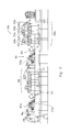
- Fig. 1 is a side elevational view of a drying section apparatus generally designated 10 for drying a web of paper W.
- the apparatus 10 includes a size press means generally designated 12 for applying size to at least one side 14 of the web W.
- a single tier dryer means generally designated 16 is disposed downstream relative to the size press means 12 for drying the web W.
- the dryer means 16 includes a plurality of dryer cylinders 18,19,20,21,22,23,24 and 25 and a plurality of vacuum rolls 26,27,28,29,30,31 and 32. Each vacuum roll, such as 27, of the plurality of vacuum rolls 26-32 is disposed between adjacent dryer cylinders 19,20 of the plurality of dryer cylinders 18-25.
- a dryer felt 34 extends around at least one of the dryer cylinders 19.
- the arrangement is such that the at least one dryer cylinder 19 is top felted as shown in Fig. 1 for permitting downward removal of broke as indicated by the arrow 36.
- Air caps means generally designated 38 are disposed above at least one of the dryer cylinders 22 for blowing air as indicated by the arrow 40 through a further felt for drying the web W disposed between the at least one dryer cylinder 22 and the further felt.
- the arrangement is such that both sides of the web W are dried during passage of the web W through the dryer means 16.
- the size press means 12 includes a frame 42 and an applicator roll 44 which is rotatably supported by the frame 42.
- the applicator roll 44 has a circumferential applicator surface 46.
- a size applicator 48 cooperates with the applicator surface 46 for applying size to the surface 46.
- the arrangement is such that at least one side 14 of the web W is brought into contact with the surface 46 downstream relative to the size applicator 48 so that size is applied to the at least one side 14 of the web W.
- the apparatus 10 also includes a further applicator roll 50 which is rotatably supported by the frame 42.
- the further roll 50 and the applicator roll 44 cooperate together to define therebetween a nip N for the passage therethrough of the web W.
- the further applicator roll 50 defines a further circumferential surface 52.
- a further size applicator 54 cooperates with the further surface 52 for applying size to the further surface 52.
- the arrangement is such that the size applied to the further surface 52 is brought into contact with a side 56 of the web W opposite to the at least one side 14 so that both sides 14 and 56 of the web W are coated with size.
- Fig. 2 is a side elevational view of a drying section apparatus according to a further embodiment of the present invention.
- Fig. 2 shows an initial single tier dryer means 58 for drying the web Wa.
- a further size press means 60 is disposed downstream relative to the initial dryer means 58 for applying size to a side 56a of the web Wa opposite to the at the least one side 14a of the web Wa.
- the apparatus 10a further includes an infrared heater 62 which is disposed between the size press means 12a and the initial dryer means 58 for drying the web Wa.
- a further infrared heater 64 is disposed between the further size press means 60 and the dryer means 16a for drying the web Wa.
- the plurality of dryer cylinders 18-25 includes an unfelted upstream cylinder 18 for guiding the web W.
- the dryer felt 34 is a looped dryer felt which is guided into contact with the unfelted dryer cylinder 18.
- the arrangement is such that the web W is transferred from the upstream unfelted dryer cylinder 18 onto the dryer felt 34 so that the web W supported by the felt 34 is guided alternately around the vacuum rolls 26-27 and the dryer cylinders 19-20 of the dryer means 16.
- the apparatus 10 includes a single tier group 66 of dryer cylinders 19,20 with the felt 34 extending alternately around the vacuum rolls 26,27 and the dryer cylinders 19,20 of the group 66.
- a further single tier group 68 of dryer cylinders 21-25 is disposed downstream relative to the group 66 and the further felt 70 extends alternately around the vacuum rolls 28-32 and the dryer cylinders 21-25 of the further group 68.
- the further felt 70 transfers the web W from the group 66 to the further group 68 and both groups 66,68 of dryer cylinders are top felted.
- the air cap means 38 is disposed above at least two of the dryer cylinders 22,23 of the further group 68.
- the air cap means 38 includes control means 72 for controlling a flow of air as indicated by the arrow 40 through the further felt 70.
- the air cap means 38 includes means 74 for heating the air so that hot air is blown by the air cap means 38 through the further felt 70 for drying a side 56 of the web W opposite to the side 14 of the web W which comes into direct surface contact with a dryer cylinder 22.
- the arrangement is such that the drying of the size applied to the web is controllably accomplished during passage of the sized web through the dryer means 16.
- the present invention provides a unique arrangement which enhances the ability to dry a sized web.
Abstract
Description
- The present invention relates to a drying section apparatus for drying a web of paper.
- More specifically, the present invention relates to a single tier dryer for drying a web.
- In the manufacture of a web of paper, a pressed web is guided around a plurality of heated dryer cylinders so that thermal energy is transferred to the web for driving therefrom the remaining moisture contained therein.
- U.S. Patent No. 5,269,074 assigned to Beloit Technologies teaches a single tier dryer means in which each of the dryer cylinders is arranged in a single row with vacuum rolls disposed between adjacent dryer cylinders. A dryer felt extends alternately around each dryer cylinder and vacuum roll for guiding the web into surface contact with each dryer cylinder for drying the web. As disclosed in the aforementioned '074 patent, each of the dryer cylinders is top felted for facilitating downward removal of broke in the event of a web breakage. The single tier concept disclosed in the '074 patent permits restrained drying of the web during the drying process. More specifically, the web is supported throughout the entire movement thereof through the dryer means thereby improving the properties of the resultant web and restraining the web against particularly cross machine directional shrinkage thereof.
- However, in many drying applications, a coating of size must be applied to the web in order to decrease the permeability of the resultant dried web thereby enhancing the printability thereof.
- When size is applied to a dried web, the sized web increases in water content so that the sized web must be further dried.
- The present invention includes the provision of a single tier dryer arrangement with air caps disposed above the dryer cylinders so that both sides of the sized web are able to be controllably dried.
- Therefore, it is a primary objective of the present invention to provide a drying section apparatus which overcomes the problems associated with the prior art arrangements for drying a sized web and which makes a considerably contribution to the art of drying a web of paper.
- Other objects and advantages of the present invention will be readily apparent to those skilled in the art by consideration of the detailed description contained hereinafter taken in conjunction with the annexed drawings.
- The present invention relates to a drying section apparatus for drying a web of paper. The apparatus includes a size press means for applying size to at least one side of the web. A single tier dryer means is disposed downstream relative to the size press means for drying the web. The dryer means includes a plurality of dryer cylinders and a plurality of vacuum rolls. Each of the vacuum rolls is disposed between adjacent dryer cylinders of the plurality of dryer cylinders.
- A dryer felt means extends around at least one of the dryer cylinders. The arrangement is such that at least one of the dryer cylinders is top felted for permitting downward removal of broke.
- Air cap means are disposed above at least one of the dryer cylinders for blowing air through the felt for drying the web disposed between the at least one dryer cylinder and the felt. The arrangement is such that both sides of the web are dried during passage of the web through the dryer means.
- In a more specific embodiment of the present invention, the size press means includes a frame and an applicator roll which is rotatably supported by the frame. The applicator roll has a circumferential applicator surface.
- A size applicator cooperates with the applicator surface for applying size to the surface. The arrangement is such that at least one of the sides of the web is brought into contact with the surface downstream relative to the size applicator so that size is applied to the at least one side of the web.
- The apparatus also includes a further applicator roll which is rotatably supported by the frame. The further roll and the applicator roll cooperate together to define therebetween a nip for the passage therethrough of the web. The further applicator roll defines a further circumferential surface.
- A further size applicator cooperates with the further surface for applying size to the further surface. The arrangement is such that the size applied to the further surface is brought into contact with a side of the web which is opposite to the at least one side so that both sides of the web are coated with size.
- In an alternative embodiment of the present invention, the drying section apparatus further includes an initial single tier dryer means for drying the web.
- A further size press means is disposed downstream relative to the initial dryer means for applying size to a side of the web opposite to the at least one side of the web.
- More specifically, the apparatus further includes an infrared heater which is disposed between the size press means and the initial dryer means for drying the web. A further infrared heat is disposed between the further size press means and the dryer means for further drying the web.
- More specifically, in the first embodiment of the present invention, the plurality of dryer cylinders includes an unfelted upstream cylinder for guiding the web.
- Also, the dryer felt means includes a looped dryer felt which is guided into contact with the unfelted upstream dryer cylinder. The arrangement is such that the web is transferred from the upstream dryer cylinder onto the dryer felt so that the web supported by the felt is guided alternately around the vacuum rolls and the dryer cylinders of the dryer means.
- In a preferred embodiment of the present invention, the apparatus further includes a single tier group of dryer cylinders with the felt extending alternately around the vacuum rolls and the dryer cylinders of the group.
- The apparatus also includes a further single tier group of dryers having a further felt which extends alternately around the vacuum rolls and the dryer cylinders of the further group. The further felt transfers the web from the group to the further group and both the group and the further group are top felted.
- More particularly, the further group is disposed downstream relative to the group of dryer cylinders and the air cap means is disposed above at least two of the dryer cylinders of the further group.
- The air cap means includes control means for controlling the flow of air through the felt means.
- More specifically, the air cap means includes means for heating the air so that hot air is blown by the air cap means through the felt means for drying a side of the web opposite to a side of the web which comes into direct surface contact with the dryer cylinder. The arrangement is such that the drying of the size applied to the web is controllably accomplished during passage of the sized web through the dryer means.
- Many modifications and variations of the present invention will be readily apparent to those skilled in the art by a consideration of the detailed description contained hereinafter taken in conjunction with the annexed drawings.
- However, such modifications and variations fall within the spirit and scope of the present invention as defined by the appended claims.
-
- Fig. 1 is a side elevational view of a drying section apparatus according to the present invention; and
- Fig. 2 is a side elevational view of a drying section apparatus according to a further embodiment of the present invention.
-
- Similar reference characters refer to similar parts throughout the various views of the drawings.
- Fig. 1 is a side elevational view of a drying section apparatus generally designated 10 for drying a web of paper W. The
apparatus 10 includes a size press means generally designated 12 for applying size to at least oneside 14 of the web W. A single tier dryer means generally designated 16 is disposed downstream relative to the size press means 12 for drying the web W. The dryer means 16 includes a plurality ofdryer cylinders adjacent dryer cylinders - A dryer felt 34 extends around at least one of the
dryer cylinders 19. The arrangement is such that the at least onedryer cylinder 19 is top felted as shown in Fig. 1 for permitting downward removal of broke as indicated by the arrow 36. Air caps means generally designated 38 are disposed above at least one of thedryer cylinders 22 for blowing air as indicated by thearrow 40 through a further felt for drying the web W disposed between the at least onedryer cylinder 22 and the further felt. The arrangement is such that both sides of the web W are dried during passage of the web W through the dryer means 16. - As shown in Fig. 1, the size press means 12 includes a
frame 42 and anapplicator roll 44 which is rotatably supported by theframe 42. Theapplicator roll 44 has acircumferential applicator surface 46. - A
size applicator 48 cooperates with theapplicator surface 46 for applying size to thesurface 46. The arrangement is such that at least oneside 14 of the web W is brought into contact with thesurface 46 downstream relative to thesize applicator 48 so that size is applied to the at least oneside 14 of the web W. - The
apparatus 10 also includes afurther applicator roll 50 which is rotatably supported by theframe 42. Thefurther roll 50 and theapplicator roll 44 cooperate together to define therebetween a nip N for the passage therethrough of the web W. Thefurther applicator roll 50 defines a furthercircumferential surface 52. - A
further size applicator 54 cooperates with thefurther surface 52 for applying size to thefurther surface 52. The arrangement is such that the size applied to thefurther surface 52 is brought into contact with aside 56 of the web W opposite to the at least oneside 14 so that bothsides - Fig. 2 is a side elevational view of a drying section apparatus according to a further embodiment of the present invention. Fig. 2 shows an initial single tier dryer means 58 for drying the web Wa. A further size press means 60 is disposed downstream relative to the initial dryer means 58 for applying size to a
side 56a of the web Wa opposite to the at the least oneside 14a of the web Wa. - As shown in Fig. 2, the apparatus 10a further includes an
infrared heater 62 which is disposed between the size press means 12a and the initial dryer means 58 for drying the web Wa. - Also, a further
infrared heater 64 is disposed between the further size press means 60 and the dryer means 16a for drying the web Wa. - As shown in the embodiment of Fig. 1, the plurality of dryer cylinders 18-25 includes an unfelted
upstream cylinder 18 for guiding the web W. - The dryer felt 34 is a looped dryer felt which is guided into contact with the
unfelted dryer cylinder 18. The arrangement is such that the web W is transferred from the upstreamunfelted dryer cylinder 18 onto the dryer felt 34 so that the web W supported by the felt 34 is guided alternately around the vacuum rolls 26-27 and the dryer cylinders 19-20 of the dryer means 16. - In a preferred embodiment of the present invention as shown in Fig. 1, the
apparatus 10 includes asingle tier group 66 ofdryer cylinders dryer cylinders group 66. - A further
single tier group 68 of dryer cylinders 21-25 is disposed downstream relative to thegroup 66 and the further felt 70 extends alternately around the vacuum rolls 28-32 and the dryer cylinders 21-25 of thefurther group 68. The further felt 70 transfers the web W from thegroup 66 to thefurther group 68 and bothgroups - The air cap means 38 is disposed above at least two of the
dryer cylinders further group 68. - More specifically, the air cap means 38 includes control means 72 for controlling a flow of air as indicated by the
arrow 40 through the further felt 70. - The air cap means 38 includes
means 74 for heating the air so that hot air is blown by the air cap means 38 through the further felt 70 for drying aside 56 of the web W opposite to theside 14 of the web W which comes into direct surface contact with adryer cylinder 22. The arrangement is such that the drying of the size applied to the web is controllably accomplished during passage of the sized web through the dryer means 16. - The present invention provides a unique arrangement which enhances the ability to dry a sized web.
Claims (13)
- A drying section apparatus for drying a web of paper, said apparatus comprising:size press means for applying size to at least one side of the web;a single tier dryer means disposed downstream relative to said size press means for drying the web;said dryer means including:a plurality of dryer cylinders;a plurality of vacuum rolls, each vacuum roll of said plurality of vacuum rolls being disposed between adjacent dryer cylinders of said plurality of dryer cylinders;a dryer felt means extending around at least one of said dryer cylinders, the arrangement being such that said at least one dryer cylinder is top felted for permitting downward removal of broke; andair cap means disposed above at least one of said dryer cylinders for blowing air through said felt means for drying the web disposed between said at least one dryer cylinder and said felt means, the arrangement being such that both sides of the web are dried during passage of the web through said dryer means.
- A dryer section apparatus as set forth in claim 1, wherein said size press means includes:a frame;an applicator roll rotatably supported by said frame, said applicator roll having a circumferential applicator surface;a size applicator cooperating with said applicator surface for applying size to said surface, the arrangement being such that said at least one side of the web is brought into contact with said surface downstream relative to said size applicator so that size is applied to said at least one side of the web.
- A drying section apparatus as set forth in claim 2, further including:a further applicator roll rotatably supported by said frame, said further roll and said applicator roll cooperating together to define therebetween a nip for the passage therethrough of the web, said further applicator roll defining a further circumferential surface;a further size applicator cooperating with said further surface for applying size to said further surface, the arrangement being such that the size applied to said further surface is brought into contact with a side of the web opposite to said at least one side so that both sides of the web are coated with size.
- A drying section apparatus as set forth in claim 2, further including:an initial single tier dryer means disposed between said applicator roll and said dryer means for drying the web;a further size press means disposed downstream relative to said initial dryer means for applying size to a side of the web opposite to said at least one side of the web.
- A drying section apparatus as set forth in claim 4, further including:an infrared heater disposed between said size press means and said initial dryer means for drying the web;a further infrared heater disposed between said further size press means and said dryer means for drying the web.
- A drying section apparatus as set forth in claim 1, wherein said plurality of dryer cylinders includes:an unfelted upstream cylinder for guiding the web.
- A drying section apparatus as set forth in claim 6, wherein said dryer felt means includes:a looped dryer felt which is guided into contact with said unfelted upstream dryer cylinder the arrangement being such that the web is transferred from said upstream dryer cylinder onto said dryer felt so that the web supported by said felt is guided alternately around said vacuum rolls and said dryer cylinders of said dryer means.
- A drying section apparatus as set forth in claim 7, further including:a single tier group of dryer cylinders, said felt extending alternately around said vacuum rolls and said dryer cylinders of said group;a further single tier group of dryer cylinders;a further felt extending alternately around said vacuum rolls and dryer cylinders of said further group;said further dryer felt transferring the web from said group to said further group, said group and said further group of dryer cylinders being top felted.
- A drying section apparatus as set forth in claim 1, wherein said dryer means further includes:a group of dryer cylinders;a further group of dryer cylinders disposed downstream relative to said group of dryer cylinders;said air cap means being disposed above at least two of said dryer cylinders of said further group.
- A drying section apparatus as set forth in claim 9, wherein said air cap means includes:control means for controlling a flow of the air through said felt means.
- A drying section apparatus as set forth in claim 10, wherein said air cap means includes:means for heating the air so that hot air is blown by said air cap means through said felt means for drying a side of the web opposite to a side of the web which comes into direct surface contact with a dryer cylinder, the arrangement being such that the drying of the size applied to the web is controllably accomplished during passage of the sized web through said dryer means.
- A drying section apparatus for drying a web of paper, said apparatus comprising:size press means for applying size to both sides of the web;a single tier dryer means disposed downstream relative to said size press means for drying the web;said dryer means including:a plurality of dryer cylinders;a plurality of vacuum rolls, each vacuum roll of said plurality of vacuum rolls being disposed between adjacent dryer cylinders of said plurality of dryer cylinders; anda dryer felt means extending around at least one of said dryer cylinders, the arrangement being such that said at least one dryer cylinder is top felted for permitting downward removal of broke.
- A drying section apparatus for drying a web of paper, said apparatus comprising:size press means for applying size to at least one side of the web;a single tier dryer means disposed downstream relative to said size press means for drying the web;said dryer means including:a plurality of dryer cylinders;a plurality of vacuum rolls, each vacuum roll of said plurality of vacuum rolls being disposed between adjacent dryer cylinders of said plurality of dryer cylinders;a dryer felt means extending around at least one of said dryer cylinders, the arrangement being such that said at least one dryer cylinder is top felted for permitting downward removal of broke; andsaid air cap means controllably blowing hot air through said felt means and onto the web, said felt means having a permeability which permits flow of heated air therethrough.
Applications Claiming Priority (2)
| Application Number | Priority Date | Filing Date | Title |
|---|---|---|---|
| US21803 | 1998-02-11 | ||
| US09/021,803 US5992040A (en) | 1998-02-11 | 1998-02-11 | Drying section apparatus |
Publications (3)
| Publication Number | Publication Date |
|---|---|
| EP0936308A2 true EP0936308A2 (en) | 1999-08-18 |
| EP0936308A3 EP0936308A3 (en) | 2000-05-24 |
| EP0936308B1 EP0936308B1 (en) | 2005-04-13 |
Family
ID=21806249
Family Applications (1)
| Application Number | Title | Priority Date | Filing Date |
|---|---|---|---|
| EP99630016A Expired - Lifetime EP0936308B1 (en) | 1998-02-11 | 1999-02-05 | A drying section apparatus |
Country Status (9)
| Country | Link |
|---|---|
| US (1) | US5992040A (en) |
| EP (1) | EP0936308B1 (en) |
| JP (1) | JPH11279977A (en) |
| KR (1) | KR100544452B1 (en) |
| BR (1) | BR9900557A (en) |
| CA (1) | CA2260726C (en) |
| DE (1) | DE69924653T2 (en) |
| ES (1) | ES2239835T3 (en) |
| ID (1) | ID23242A (en) |
Cited By (3)
| Publication number | Priority date | Publication date | Assignee | Title |
|---|---|---|---|---|
| WO2004001133A2 (en) * | 2002-06-24 | 2003-12-31 | Voith Paper Patent Gmbh | Device for coating and drying the front and back of a web, particularly one consisting of paper or cardboard |
| CN101466892B (en) * | 2006-06-12 | 2011-06-29 | 美卓造纸机械公司 | Hood for web forming, press and/or dryer section |
| WO2023169763A1 (en) * | 2022-03-09 | 2023-09-14 | Voith Patent Gmbh | Application unit and method |
Families Citing this family (3)
| Publication number | Priority date | Publication date | Assignee | Title |
|---|---|---|---|---|
| US6079116A (en) * | 1998-11-06 | 2000-06-27 | Valmet-Karlstad Ab | Duct configuration for a through-air drying apparatus in a papermaking machine |
| US7563326B2 (en) * | 2002-06-24 | 2009-07-21 | Voith Paper Patent Gmbh | Device for coating and drying both sides of a material web of paper or board |
| CA2894946C (en) * | 2011-12-20 | 2021-01-12 | The Royal Institution For The Advancement Of Learning/Mcgill University | Method and apparatus for manufacturing lignocellulosic materials with improved properties |
Citations (3)
| Publication number | Priority date | Publication date | Assignee | Title |
|---|---|---|---|---|
| EP0726353A2 (en) * | 1995-02-01 | 1996-08-14 | Valmet Corporation | Method for producing surface-treated paper and dry end of a paper machine |
| WO1996032534A1 (en) * | 1995-04-12 | 1996-10-17 | Valmet Corporation | Dryer-section concept and method in the drying of a paper/board web |
| WO1998027273A1 (en) * | 1996-12-03 | 1998-06-25 | Valmet Corporation | Method for drying of paper and dry end of a paper machine |
Family Cites Families (4)
| Publication number | Priority date | Publication date | Assignee | Title |
|---|---|---|---|---|
| DE68907058T2 (en) * | 1989-11-16 | 1993-09-16 | Beloit Corp | DEVICE FOR COATING. |
| DE9414963U1 (en) * | 1994-09-16 | 1994-11-03 | Voith Gmbh J M | Dryer section |
| US5592751A (en) * | 1994-11-23 | 1997-01-14 | Voith Sulzer Papiermaschinen Gmbh | Dryer section having combination of single and double tier dryer groups |
| US5634402A (en) * | 1995-10-12 | 1997-06-03 | Research, Incorporated | Coating heater system |
-
1998
- 1998-02-11 US US09/021,803 patent/US5992040A/en not_active Expired - Fee Related
-
1999
- 1999-02-04 CA CA002260726A patent/CA2260726C/en not_active Expired - Fee Related
- 1999-02-05 EP EP99630016A patent/EP0936308B1/en not_active Expired - Lifetime
- 1999-02-05 ES ES99630016T patent/ES2239835T3/en not_active Expired - Lifetime
- 1999-02-05 DE DE69924653T patent/DE69924653T2/en not_active Expired - Lifetime
- 1999-02-05 ID IDP990081D patent/ID23242A/en unknown
- 1999-02-09 KR KR1019990004394A patent/KR100544452B1/en not_active IP Right Cessation
- 1999-02-09 BR BR9900557-3A patent/BR9900557A/en not_active IP Right Cessation
- 1999-02-10 JP JP11032308A patent/JPH11279977A/en active Pending
Patent Citations (3)
| Publication number | Priority date | Publication date | Assignee | Title |
|---|---|---|---|---|
| EP0726353A2 (en) * | 1995-02-01 | 1996-08-14 | Valmet Corporation | Method for producing surface-treated paper and dry end of a paper machine |
| WO1996032534A1 (en) * | 1995-04-12 | 1996-10-17 | Valmet Corporation | Dryer-section concept and method in the drying of a paper/board web |
| WO1998027273A1 (en) * | 1996-12-03 | 1998-06-25 | Valmet Corporation | Method for drying of paper and dry end of a paper machine |
Cited By (5)
| Publication number | Priority date | Publication date | Assignee | Title |
|---|---|---|---|---|
| WO2004001133A2 (en) * | 2002-06-24 | 2003-12-31 | Voith Paper Patent Gmbh | Device for coating and drying the front and back of a web, particularly one consisting of paper or cardboard |
| WO2004001133A3 (en) * | 2002-06-24 | 2004-07-08 | Voith Paper Patent Gmbh | Device for coating and drying the front and back of a web, particularly one consisting of paper or cardboard |
| CN100404758C (en) * | 2002-06-24 | 2008-07-23 | 沃伊斯造纸专利有限公司 | Device for coating and drying the front and back of a web, particularly one consisting of paper or cardboard |
| CN101466892B (en) * | 2006-06-12 | 2011-06-29 | 美卓造纸机械公司 | Hood for web forming, press and/or dryer section |
| WO2023169763A1 (en) * | 2022-03-09 | 2023-09-14 | Voith Patent Gmbh | Application unit and method |
Also Published As
| Publication number | Publication date |
|---|---|
| CA2260726A1 (en) | 1999-08-11 |
| CA2260726C (en) | 2004-02-03 |
| BR9900557A (en) | 2000-02-29 |
| ES2239835T3 (en) | 2005-10-01 |
| DE69924653T2 (en) | 2006-02-09 |
| US5992040A (en) | 1999-11-30 |
| EP0936308A3 (en) | 2000-05-24 |
| DE69924653D1 (en) | 2005-05-19 |
| EP0936308B1 (en) | 2005-04-13 |
| ID23242A (en) | 2000-03-30 |
| JPH11279977A (en) | 1999-10-12 |
| KR100544452B1 (en) | 2006-01-24 |
| KR19990072509A (en) | 1999-09-27 |
Similar Documents
| Publication | Publication Date | Title |
|---|---|---|
| US5862613A (en) | Paper machine and methods for drying a paper web | |
| US5557860A (en) | Dryer section with moistening devices at latter ends | |
| JP2909018B2 (en) | Method for producing surface-treated paper and dry section of paper machine | |
| US5968590A (en) | Method for drying a surface-treated paper web in an after-dryer of a paper machine and after-dryer of a paper machine | |
| US6001421A (en) | Method for drying paper and a dry end of a paper machine | |
| FI105935B (en) | Method for drying paper and dry end of paper machine | |
| FI104001B (en) | drying Lot | |
| US5771603A (en) | Dryer section | |
| US6490813B1 (en) | Drying and smoothing unit for webs of fibrous material | |
| US5992040A (en) | Drying section apparatus | |
| EP1012383B1 (en) | Method for control of the curl of paper in the dryer section of a paper machine and paper or board machine | |
| US5632101A (en) | All top-felted single-tier drying section with post drying section curl control | |
| JP4027987B2 (en) | Method for drying surface-treated waste paper web or equivalent in post-drying machine of paper machine and post-drying machine for implementing the method in paper machine | |
| US5983523A (en) | Method for controlling curl of paper in a dryer section of a paper machine and a paper or board machine | |
| US5592751A (en) | Dryer section having combination of single and double tier dryer groups | |
| EP2722434B1 (en) | Belt assembly for moving a web from a press section of a paper- or board-making machine to a dryer section of the machine | |
| CA1299864C (en) | Dryer section apparatus | |
| CA2211185A1 (en) | Single tier dryer section with dual reversing rolls | |
| EP1015690A1 (en) | Method for drying a surface-treated paper web or equivalent in an after-dryer of a paper machine and after-dryer carrying out the method in a paper machine | |
| US6159343A (en) | Press-to-dryer apparatus | |
| WO2000000696A1 (en) | Method and apparatus for moistening the paper web in the drying section | |
| WO1996023931A1 (en) | A sheet transfer apparatus | |
| FI119884B (en) | Method and apparatus for wetting a web |
Legal Events
| Date | Code | Title | Description |
|---|---|---|---|
| PUAI | Public reference made under article 153(3) epc to a published international application that has entered the european phase |
Free format text: ORIGINAL CODE: 0009012 |
|
| AK | Designated contracting states |
Kind code of ref document: A2 Designated state(s): DE ES FI FR GB IT SE |
|
| AX | Request for extension of the european patent |
Free format text: AL;LT;LV;MK;RO;SI |
|
| PUAL | Search report despatched |
Free format text: ORIGINAL CODE: 0009013 |
|
| AK | Designated contracting states |
Kind code of ref document: A3 Designated state(s): AT BE CH CY DE DK ES FI FR GB GR IE IT LI LU MC NL PT SE |
|
| AX | Request for extension of the european patent |
Free format text: AL;LT;LV;MK;RO;SI |
|
| 17P | Request for examination filed |
Effective date: 20001027 |
|
| AKX | Designation fees paid |
Free format text: DE ES FI FR GB IT SE |
|
| 17Q | First examination report despatched |
Effective date: 20021101 |
|
| GRAP | Despatch of communication of intention to grant a patent |
Free format text: ORIGINAL CODE: EPIDOSNIGR1 |
|
| GRAS | Grant fee paid |
Free format text: ORIGINAL CODE: EPIDOSNIGR3 |
|
| GRAA | (expected) grant |
Free format text: ORIGINAL CODE: 0009210 |
|
| AK | Designated contracting states |
Kind code of ref document: B1 Designated state(s): DE ES FI FR GB IT SE |
|
| REG | Reference to a national code |
Ref country code: GB Ref legal event code: FG4D |
|
| REF | Corresponds to: |
Ref document number: 69924653 Country of ref document: DE Date of ref document: 20050519 Kind code of ref document: P |
|
| REG | Reference to a national code |
Ref country code: SE Ref legal event code: TRGR |
|
| REG | Reference to a national code |
Ref country code: ES Ref legal event code: FG2A Ref document number: 2239835 Country of ref document: ES Kind code of ref document: T3 |
|
| PLBE | No opposition filed within time limit |
Free format text: ORIGINAL CODE: 0009261 |
|
| STAA | Information on the status of an ep patent application or granted ep patent |
Free format text: STATUS: NO OPPOSITION FILED WITHIN TIME LIMIT |
|
| ET | Fr: translation filed | ||
| 26N | No opposition filed |
Effective date: 20060116 |
|
| PGFP | Annual fee paid to national office [announced via postgrant information from national office to epo] |
Ref country code: IT Payment date: 20080223 Year of fee payment: 10 Ref country code: GB Payment date: 20080220 Year of fee payment: 10 |
|
| PGFP | Annual fee paid to national office [announced via postgrant information from national office to epo] |
Ref country code: ES Payment date: 20090219 Year of fee payment: 11 |
|
| PGFP | Annual fee paid to national office [announced via postgrant information from national office to epo] |
Ref country code: FI Payment date: 20090217 Year of fee payment: 11 |
|
| PGFP | Annual fee paid to national office [announced via postgrant information from national office to epo] |
Ref country code: SE Payment date: 20090216 Year of fee payment: 11 |
|
| GBPC | Gb: european patent ceased through non-payment of renewal fee |
Effective date: 20090205 |
|
| PGFP | Annual fee paid to national office [announced via postgrant information from national office to epo] |
Ref country code: FR Payment date: 20090213 Year of fee payment: 11 |
|
| PG25 | Lapsed in a contracting state [announced via postgrant information from national office to epo] |
Ref country code: GB Free format text: LAPSE BECAUSE OF NON-PAYMENT OF DUE FEES Effective date: 20090205 |
|
| EUG | Se: european patent has lapsed | ||
| REG | Reference to a national code |
Ref country code: FR Ref legal event code: ST Effective date: 20101029 |
|
| PG25 | Lapsed in a contracting state [announced via postgrant information from national office to epo] |
Ref country code: FI Free format text: LAPSE BECAUSE OF NON-PAYMENT OF DUE FEES Effective date: 20100205 |
|
| PG25 | Lapsed in a contracting state [announced via postgrant information from national office to epo] |
Ref country code: FR Free format text: LAPSE BECAUSE OF NON-PAYMENT OF DUE FEES Effective date: 20100301 |
|
| REG | Reference to a national code |
Ref country code: ES Ref legal event code: FD2A Effective date: 20110324 |
|
| PG25 | Lapsed in a contracting state [announced via postgrant information from national office to epo] |
Ref country code: IT Free format text: LAPSE BECAUSE OF NON-PAYMENT OF DUE FEES Effective date: 20090205 |
|
| PG25 | Lapsed in a contracting state [announced via postgrant information from national office to epo] |
Ref country code: ES Free format text: LAPSE BECAUSE OF NON-PAYMENT OF DUE FEES Effective date: 20110310 |
|
| PG25 | Lapsed in a contracting state [announced via postgrant information from national office to epo] |
Ref country code: ES Free format text: LAPSE BECAUSE OF NON-PAYMENT OF DUE FEES Effective date: 20100206 |
|
| PGFP | Annual fee paid to national office [announced via postgrant information from national office to epo] |
Ref country code: DE Payment date: 20120221 Year of fee payment: 14 |
|
| PG25 | Lapsed in a contracting state [announced via postgrant information from national office to epo] |
Ref country code: SE Free format text: LAPSE BECAUSE OF NON-PAYMENT OF DUE FEES Effective date: 20100206 |
|
| REG | Reference to a national code |
Ref country code: DE Ref legal event code: R119 Ref document number: 69924653 Country of ref document: DE Effective date: 20130903 |
|
| PG25 | Lapsed in a contracting state [announced via postgrant information from national office to epo] |
Ref country code: DE Free format text: LAPSE BECAUSE OF NON-PAYMENT OF DUE FEES Effective date: 20130903 |