EP0936281A1 - Method and apparatus for three-dimensional processing of filamentary substrates - Google Patents
Method and apparatus for three-dimensional processing of filamentary substrates Download PDFInfo
- Publication number
- EP0936281A1 EP0936281A1 EP99300844A EP99300844A EP0936281A1 EP 0936281 A1 EP0936281 A1 EP 0936281A1 EP 99300844 A EP99300844 A EP 99300844A EP 99300844 A EP99300844 A EP 99300844A EP 0936281 A1 EP0936281 A1 EP 0936281A1
- Authority
- EP
- European Patent Office
- Prior art keywords
- filamentary substrate
- substrate
- tubular member
- filamentary
- base
- Prior art date
- Legal status (The legal status is an assumption and is not a legal conclusion. Google has not performed a legal analysis and makes no representation as to the accuracy of the status listed.)
- Granted
Links
Images

Classifications
-
- C—CHEMISTRY; METALLURGY
- C23—COATING METALLIC MATERIAL; COATING MATERIAL WITH METALLIC MATERIAL; CHEMICAL SURFACE TREATMENT; DIFFUSION TREATMENT OF METALLIC MATERIAL; COATING BY VACUUM EVAPORATION, BY SPUTTERING, BY ION IMPLANTATION OR BY CHEMICAL VAPOUR DEPOSITION, IN GENERAL; INHIBITING CORROSION OF METALLIC MATERIAL OR INCRUSTATION IN GENERAL
- C23C—COATING METALLIC MATERIAL; COATING MATERIAL WITH METALLIC MATERIAL; SURFACE TREATMENT OF METALLIC MATERIAL BY DIFFUSION INTO THE SURFACE, BY CHEMICAL CONVERSION OR SUBSTITUTION; COATING BY VACUUM EVAPORATION, BY SPUTTERING, BY ION IMPLANTATION OR BY CHEMICAL VAPOUR DEPOSITION, IN GENERAL
- C23C14/00—Coating by vacuum evaporation, by sputtering or by ion implantation of the coating forming material
- C23C14/22—Coating by vacuum evaporation, by sputtering or by ion implantation of the coating forming material characterised by the process of coating
- C23C14/56—Apparatus specially adapted for continuous coating; Arrangements for maintaining the vacuum, e.g. vacuum locks
- C23C14/562—Apparatus specially adapted for continuous coating; Arrangements for maintaining the vacuum, e.g. vacuum locks for coating elongated substrates
-
- C—CHEMISTRY; METALLURGY
- C23—COATING METALLIC MATERIAL; COATING MATERIAL WITH METALLIC MATERIAL; CHEMICAL SURFACE TREATMENT; DIFFUSION TREATMENT OF METALLIC MATERIAL; COATING BY VACUUM EVAPORATION, BY SPUTTERING, BY ION IMPLANTATION OR BY CHEMICAL VAPOUR DEPOSITION, IN GENERAL; INHIBITING CORROSION OF METALLIC MATERIAL OR INCRUSTATION IN GENERAL
- C23C—COATING METALLIC MATERIAL; COATING MATERIAL WITH METALLIC MATERIAL; SURFACE TREATMENT OF METALLIC MATERIAL BY DIFFUSION INTO THE SURFACE, BY CHEMICAL CONVERSION OR SUBSTITUTION; COATING BY VACUUM EVAPORATION, BY SPUTTERING, BY ION IMPLANTATION OR BY CHEMICAL VAPOUR DEPOSITION, IN GENERAL
- C23C14/00—Coating by vacuum evaporation, by sputtering or by ion implantation of the coating forming material
- C23C14/22—Coating by vacuum evaporation, by sputtering or by ion implantation of the coating forming material characterised by the process of coating
- C23C14/50—Substrate holders
- C23C14/505—Substrate holders for rotation of the substrates
Definitions
- the present invention relates to a method and apparatus for nonplanar micro-fabrication and processing on flexible, filamentary structures. More particularly, the present invention relates to a method and apparatus for physical vapor deposition of materials on long, flexible filamentary substrates by holding each end of a deposition area on the filament to maintain the filament in a substantially straight configuration and to physically mask the filament outside the deposition area, and by simultaneously rotating the filament about one or two axes to uniformly deposit the material on the filament.
- Lithographic techniques have been utilized for some time in the manufacture especially of integrated circuit boards and semiconductor devices and related products.
- the products manufactured have typically included planar surfaces to which the lithographic techniques were applied.
- Such techniques have proven extremely effective in the precise manufacturing and formation of very small details in the product.
- attempts to apply such techniques to other than planar surfaces have proven difficult, if not unachievable, until recently.
- U.S. Patent 5,106,455 issued April 21, 1992, to Jacobsen et al. discloses a method and apparatus for fabricating microstructures using nonplanar, exposure beam lithography.
- U.S. Patent 5,269,882, issued December 14, 1993, to Jacobsen discloses a method and apparatus for fabricating thin-film semiconductor devices using nonplanar, exposure beam lithography.
- a variety of semiconductor devices can be formed on three-dimensional substrates, again such as cylinders.
- the methods and apparatus disclosed in the above two patents provide for fabrication of individual microstructures or thin-film semiconductor devices in a type of batch processing approach.
- U.S. Patent 5,273,622, issued December 29, 1993, to Jacobsen discloses a continuous processing approach for fabricating microstructures and thin-film semiconductor devices.
- microstructures are finding use in a variety of areas including medical devices, robotics, navigation equipment, motors and similar equipment.
- U.S. Patent 5,481,184, issued January 2, 1996, to Jacobsen discloses a system for movement actuators and sensors on very small mechanical parts, such as fibers and filaments.
- U.S. Patent 5,270,485, issued December 14, 1993, to Jacobsen discloses a three-dimensional circuit structure with electrical components formed on the surfaces of elongated cylindrical substrates.
- the problems faced in fabricating detailed features of these microstructures include the extremely small size of the features and structures and also the nonplanar nature of the structures.
- the structures may be relatively long and flexible.
- a fixture apparatus having a tubular member for holding the Filamentary substrate and rotatably disposed on a base.
- the tubular member has an opening through which material may be deposited on the surface of the filamentary substrate.
- a pair of tubes are slidingly disposed in the tubular member on either side of the opening defining a deposition area on the surface of the filamentary substrate. The tubes may be moved toward one another or away from each other to adjust the size of the deposition area.
- a pair of baskets are each disposed on the ends of the tubular member in which the filamentary substrate is coiled for storage.
- the tubes may be formed integrally with the tubular member or be omitted altogether.
- the tubes and/or the tubular member hold the filamentary substrate on both sides of the deposition area to maintain the straight configuration of the filamentary substrate and to prevent sagging or drooping.
- long, flexible, filamentary substrates may have material deposited on their surfaces with the tubes and/or tubular member maintaining the straight configuration and the baskets storing the excess length. This allows for filamentary substrates that are long, or for a series of structures on the same filamentary substrate, to be processed.
- tubes and/or tubular member physically masks the filamentary substrate on both sides of the deposition area. Physically masking the filamentary substrate maintains sharp material edges and prevents undesired material deposition on the filamentary substrate outside the deposition area.
- the fixture apparatus also has a traction wheel fixedly coupled to one end of the tubular member and disposed on a circular path of the base.
- the other end of the tubular member is rotatably coupled to a rotating member of the base.
- the rotating member of the base turns and causes the tubular member, and thus the filamentary substrate, to turn about a vertical axis.
- the traction wheel also rolls on the base about the vertical axis as the rotating member turns.
- the tubular member, and thus the filamentary substrate is also rotated about a horizontal axis, or longitudinal axis of the tubular member. Therefore, the filamentary substrate is rotated about two different axes, horizontal and vertical, to uniformly deposit material on the surface of the substrate.
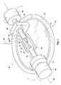
- FIG. 1 is a perspective view of a preferred embodiment of the apparatus for holding and rotating a filamentary substrate of the present invention.
- FIG. 2 is a top view of a preferred embodiment of the apparatus for holding and rotating a filamentary substrate of the present invention.
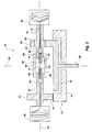
- FIG. 3 is a cross-sectional view of a preferred embodiment of apparatus for holding and rotating a filamentary substrate of the present invention taken along line 3-3 of FIG. 2.
- the filamentary substrate 12 may be an optical fiber.
- the material deposited on the filamentary substrate 12 may be platinum or PZT.
- the deposition of a metal, such as platinum, and a piezoceramic, such as PZT, on an optical fiber is useful in the construction of filamentary sensors and actuators.
- the filamentary substrate and deposited material may be selected to create the desired microstructure, including three-dimensional mechanical parts and three-dimensional electrical components.
- the filamentary substrate may be a cylindrical bar and the material deposited may be a conductor material or insulator material to create nonplanar semiconductor devices.
- the material deposited may be a semiconductor material, such as amorphous silicon.
- the filamentary substrate may be a polymer fiber, a metal filament or fiber, a ceramic fiber, or a glass fiber.
- the fixture apparatus 10 has a base or base member indicated generally at 13.
- the base 13 is disposable within a deposition chamber (not shown) or exposed to a deposition source (not shown).
- the base 13 may be cylindrical or have a circular wall 14 and have a rotating member 15, the purpose of which will be discussed below.
- the fixture apparatus 10 also advantageously has an elongated, hollow tubular member 16 for holding the filamentary substrate 12.
- the tubular member 16 is rotatably disposed on the base 12.
- the tubular member. 16 is hollow, or has an elongated opening 18 extended through the tubular member along its length from one end to the other, as shown in FIG. 3.
- the elongated opening 18 is configured for receiving and containing the long, flexible substrate 12, which extends through the tubular member.
- the tubular member 16 has an opening 20 formed therein generally in the center of the length of the tubular member 16 through which the filamentary substrate 12 is exposed to the deposition source and through which material is deposited on the surface of the filamentary substrate.
- the opening 20 is formed by a gap separating a first portion 22 and a second portion 24 of the tubular member 16.
- a pair of braces 26 and 28 support and join the first and second portions 22 and 24 of the tubular member 16 and maintain the portions 22 and 24 in axial alignment.
- the fixture apparatus 10 advantageously has a pair of movable tubes 30 and 32 which are each slidingly disposed in the tubular member 16 at opposing sides of the opening 20 for holding and/or masking the filamentary substrate 12.
- the tubes 30 and 32 are slidingly disposed in first and second holes 36 and 38 formed in the first and second portions 22 and 24 of the tubular member, respectively, as shown in FIG. 3.
- the holes 36 and 38 are sized and configured to allow the tubes 30 and 32 to slide back and forth.
- the tubes 30 and 32 define a deposition area 40 on the filamentary substrate 12, or the surface area of the filamentary substrate to be exposed.
- the tubes 30 and 32 may be slid together or apart to decrease or increase the size of the deposition area 40.
- tubes 3C and 32 may be formed integrally with the tubular member 16 or may be extensions of the tubular member.
- the tubes 30 and 32 are hollow, or have an elongated openings 42 and 44 extending through the tubes from one end to the other, as shown in FIG. 3.
- the elongated openings 42 and 44 are sized and configured to receive and hold the filamentary substrate 12.
- the tubes 30 and 32, or tubular member 16 advantageously hold the filamentary substrate 12 on both sides of the deposition area 40 to prevent the filamentary substrate 12 from drooping or sagging, or to maintain the filamentary substrate 12 in a substantially straight configuration. Therefore, long, flexible, filamentary substrates, or a series of filamentary structures formed in one long length, may be processed without the filamentary substrate bending.
- the tubular member and/or moveable tubes are some examples of a holding means for holding the filamentary substrate in a substantially straight configuration. It is of course understood that different methods or devices may be used in place of the tubular member and/or tubes. For example, a pair of clamps may hold the filamentary substrate on either side of the deposition area.
- the tubes 30 and 32, or tubular member 16 advantageously physically masks the portion of the filamentary substrate 12 outside the deposition area 40.
- the tubes 30 and 32 maintain sharp material edges on the filamentary substrate and prevent undesired material deposition on the filamentary substrate.
- the moveable tubes and/or tubular member are some examples of masking means for preventing undesirable material deposition on the tilamentary substrate. It is of course understood that different methods or devices may be used in place of the tubes and/or tubular member.
- the filamentary substrate may be masked by a material applied directly to its surface.
- a pair of baskets, drums, or spools 46 and 48 are each advantageously disposed on opposing ends of the tubular member 16 in which the filamentary substrate 12 is coiled or otherwise disposed for storage.
- the filamentary substrate 12 is fed from one basket 46, through the tubular member 16 where it is exposed to the deposition source at the opening 20, and into the other basket 48. In this manner, relatively long, filamentary substrates may be processed without breaking the length of the filamentary substrate.
- the base 13 has a circular wall or path 14 and a rotating member 15.
- the base 13 may be cylindrical or disk-shaped and have a cylindrical or disk-shaped cavity formed therein, forming the circular wall 14.
- the rotating member 15 may be disposed within the cylindrical cavity and rotate within the circular path 14.
- a shaft 49 is coupled to the rotating member 15 and causes it to rotate, as shown in FIG. 3.
- a motor or the like (not shown) may be used to turn the shaft 49 and the rotating member.
- a bracket 50 is formed on the rotating member 15.
- the base 13 and rotating member 15 are shown as cylindrical or disk-shaped, it is of course understood that the illustrated shapes are unnecessary to the present invention.
- the base may be merely a plate and the rotating member an arm rotating with respect to the plate.
- the tubular member 16 is rotatably disposed on the base 13.
- the fixture apparatus 10 has a traction wheel 51 coupled to one side of the tubular member 16 and disposed on the base 13.
- the traction wheel 51 is rollingly disposed on the circular path 14 of the base.
- the other side of the tubular member 16 is rotatably coupled to the base 13 by a bearing 52, as shown in FIGS. 1 and 3.
- the bearing 52 is disposed in the bracket 50.
- the wheel 51 and bearing 52 support the tubular member 16 above the surface of the base.
- the shaft 50 is caused to rotate which turns the rotating member 15 about a vertical axis 54.
- the vertical axis 54 is generally perpendicular to the horizontal base 13 and passes generally through the center of the tubular member 16 and deposition area 20. As the shaft 50 and the rotating member 15 turn, the tubular member 16, and thus the filamentary substrate 12, turns about the vertical axis 54.
- the traction wheel 51 is fixedly coupled to the tubular member 16 so that as the traction wheel rolls about the vertical axis 54 on the base 13, the tubular member 16 rotates about not only the vertical axis 54, but a horizontal axis 56 as well.
- the horizontal axis 56 is generally concentric with a longitudinal axis of the tubular member 16 and filamentary substrate 12. Because the traction wheel 51 is fixed to the tubular member 16 and rolls about the circular path 14, the tubular member 16 rotates about its longitudinal axis, or the horizontal axis 56. In addition, the tubular member 16 is turned about the vertical axis 54 by the turning of the rotating member 15.
- the bearing 52 is disposed in the bracket 50 and rotatably couples the tubular member 16 to the rotating member 15, or base 13, so that as the traction wheel 51 rolls around the vertical axis 54 on the base 13, the bearing 52 permits the tubular member 16 to rotate about the horizontal axis 56 with the traction wheel 51. Because the tubular member 16 is fixed to the traction wheel 51, it rotates with the traction wheel in the same direction as the traction wheel.
- the bearing 52 is coupled to the tubular member 16 to allow the tubular member to rotated with the traction wheel 51.
- the shaft, rotating member, traction wheel, bearing, and/or motor are some examples of a rotating means for rotating the filamentary substrate about two axes. It is of course understood that different methods or devices may be used. For example, separate motors may be used to turn the filamentary substrate about the vertical axis and rotate it about its longitudinal axis. Gears and/or drive belts may be used to turn and rotate the filamentary substrate.
- the bearing may be disposed in a second wheel and the tubular member caused to turn about the vertical axis on the traction wheel and second wheel/bearing.
- An illustrative process for use with the fixture apparatus of FIGs. 1-3 could include first holding the filamentary substrate on both sides of the deposition area to prevent the filamentary substrate from sagging or drooping.
- a length of the filamentary substrate is coiled or otherwise disposed in the basket 46 for storage.
- An end of the filamentary substrate is fed into the tubular member 16 and drawn through the opening 20 so that the deposition area is positioned in the opening.
- the end is coiled or otherwise disposed in the basket 48 for storage.
- Both sides of the deposition area 40 are physically masked to provide sharp edge definition of the material and provent the material from tapering off outside the deposition area.
- the filamentary substrate is fed through the tubular member, it is also fed through the pair of movable tubes 30 and 32.
- the tubes 30 and 32 are slid together or apart to adjust the size of the deposition area.
- the tubular member 16 may also be used to physically mask the filamentary substrate by forming the movable tubes with the tubular member or by omitting the movable tubes all together.
- the movable tubes may be used to hold the filamentary substrate to maintain it in a substantially straight configuration.
- the deposition area of the filamentary substrate is exposed to a deposition source while the filamentary substrate is rotated about two different axes.
- the rotating member 15 turns, the tubular member 16, and thus the filamentary substrate 12, is turned about the vertical axis 54.
- the wheel 51 rolls on the base 13, causing the tubular member 16, and thus the filamentary substrate 12, to rotate about the horizontal axis 56 concentric with its longitudinal axis.
- the filamentary substrate is a single unit, it may then be removed from the tubular member. If the filamentary substrate comprises a series of units, the filamentary substrate may be advanced through the tubular member so that the next deposition area is exposed in the opening. The portions of the filamentary substrate to be processed and the portion already processed are stored in the baskets.
- the filamentary substrate may be an optical fiber, a polymer fiber, a metal filament or fiber, a ceramic fiber, a glass fiber, etc.
- the material deposited may be a metal such as platinum, an insulator, a semiconductor material such as amorphous silicon, a piezoceramic such as PZT, etc.
- the material may be deposited by physical vapor deposition (PVD) which includes sputtering, evaporation, etc.
- portions of the deposition area of the filamentary substrate may be photolithographically. masked by a photoresist material in a desired pattern.
- the photoresist material may be deposited onto the filamentary substrate and then patterned.
- portions of the deposition area are lithographically masked, defining masked area, while other portions are exposed, defining exposed areas. Therefore, the exposed area for deposition is defined by the photoresist pattern within the physically masked deposition area.
- the present invention has been described and illustrated as simultaneously rotating the filamentary substrate about two axes, the vertical axis and the horizontal or longitudinal axis, it is of course understood that the method and apparatus of the present invention may be used to rotate the filamentary substrate about a single axis.
- the rotating member may turn the tubular member, and thus the filamentary substrate, about the vertical axis with the traction wheel disengaged from the base so that the tubular member and filamentary substrate do not turn about the longitudinal or horizontal axis.
- the traction wheel may be a gear that turns the tubular member, and thus the filamentary substrate, about the longitudinal or horizontal axis with the rotating member or shaft disengaged so that the tubular member and filamentary substrate do not turn about the vertical axis.
Abstract
Description
- The present invention relates to a method and apparatus for nonplanar micro-fabrication and processing on flexible, filamentary structures. More particularly, the present invention relates to a method and apparatus for physical vapor deposition of materials on long, flexible filamentary substrates by holding each end of a deposition area on the filament to maintain the filament in a substantially straight configuration and to physically mask the filament outside the deposition area, and by simultaneously rotating the filament about one or two axes to uniformly deposit the material on the filament.
- Lithographic techniques have been utilized for some time in the manufacture especially of integrated circuit boards and semiconductor devices and related products. The products manufactured have typically included planar surfaces to which the lithographic techniques were applied. Such techniques have proven extremely effective in the precise manufacturing and formation of very small details in the product. However, attempts to apply such techniques to other than planar surfaces have proven difficult, if not unachievable, until recently. With recent developments in nonplanar lithography, the fabrication of microstructures, including both three-dimensional mechanical parts and three-dimensional electrical components, has become more readily achievable. U.S. Patent 5,106,455, issued April 21, 1992, to Jacobsen et al. discloses a method and apparatus for fabricating microstructures using nonplanar, exposure beam lithography. Using this method and apparatus, very fine, precise and detailed physical structures can be formed on very small three-dimensional objects such as, for example, cylinders. U.S. Patent 5,269,882, issued December 14, 1993, to Jacobsen discloses a method and apparatus for fabricating thin-film semiconductor devices using nonplanar, exposure beam lithography. In particular, a variety of semiconductor devices can be formed on three-dimensional substrates, again such as cylinders. The methods and apparatus disclosed in the above two patents provide for fabrication of individual microstructures or thin-film semiconductor devices in a type of batch processing approach. U.S. Patent 5,273,622, issued December 29, 1993, to Jacobsen discloses a continuous processing approach for fabricating microstructures and thin-film semiconductor devices. Such microstructures are finding use in a variety of areas including medical devices, robotics, navigation equipment, motors and similar equipment. U.S. Patent 5,481,184, issued January 2, 1996, to Jacobsen discloses a system for movement actuators and sensors on very small mechanical parts, such as fibers and filaments. U.S. Patent 5,270,485, issued December 14, 1993, to Jacobsen discloses a three-dimensional circuit structure with electrical components formed on the surfaces of elongated cylindrical substrates. With the development of these very small (termed "micro") mechanical devices and electrical elements, the ability to fabricate detailed features of such devices and elements in an efficient and precise way is greatly desired.
- The problems faced in fabricating detailed features of these microstructures include the extremely small size of the features and structures and also the nonplanar nature of the structures. In addition, the structures may be relatively long and flexible.
- It is an object of the present invention to provide a method and apparatus for fabricating microstructures utilizing lithographic techniques.
- It is another object of the present invention to provide such a method and apparatus which allows the fabrication of fine details over nonplanar surface areas of a workpiece.
- It is yet another object of the present invention to provide such a method and apparatus in which an elongated workpiece or substrate may be processed.
- It is yet another object of the present invention to provide such a method and apparatus in which a flexible, filamentary workpiece or substrate may be processed.
- It is a further object of the present invention to provide a method and apparatus for depositing a material on a nonplanar, flexible filamentary substrate by physical vapor deposition processes.
- These and other objects and advantages of the present invention are realized in a fixture apparatus having a tubular member for holding the Filamentary substrate and rotatably disposed on a base. The tubular member has an opening through which material may be deposited on the surface of the filamentary substrate. A pair of tubes are slidingly disposed in the tubular member on either side of the opening defining a deposition area on the surface of the filamentary substrate. The tubes may be moved toward one another or away from each other to adjust the size of the deposition area. A pair of baskets are each disposed on the ends of the tubular member in which the filamentary substrate is coiled for storage.
- The tubes may be formed integrally with the tubular member or be omitted altogether. The tubes and/or the tubular member hold the filamentary substrate on both sides of the deposition area to maintain the straight configuration of the filamentary substrate and to prevent sagging or drooping.
- Therefore, long, flexible, filamentary substrates may have material deposited on their surfaces with the tubes and/or tubular member maintaining the straight configuration and the baskets storing the excess length. This allows for filamentary substrates that are long, or for a series of structures on the same filamentary substrate, to be processed.
- In addition, the tubes and/or tubular member physically masks the filamentary substrate on both sides of the deposition area. Physically masking the filamentary substrate maintains sharp material edges and prevents undesired material deposition on the filamentary substrate outside the deposition area.
- The fixture apparatus also has a traction wheel fixedly coupled to one end of the tubular member and disposed on a circular path of the base. The other end of the tubular member is rotatably coupled to a rotating member of the base. The rotating member of the base turns and causes the tubular member, and thus the filamentary substrate, to turn about a vertical axis. The traction wheel also rolls on the base about the vertical axis as the rotating member turns. As the wheel rolls about the vertical axis, the tubular member, and thus the filamentary substrate, is also rotated about a horizontal axis, or longitudinal axis of the tubular member. Therefore, the filamentary substrate is rotated about two different axes, horizontal and vertical, to uniformly deposit material on the surface of the substrate.
- These and other objects, features, advantages and alternative aspects of the present invention will become apparent to those skilled in the art from a consideration of the following detailed description taken in combination with the accompanying drawings.
- FIG. 1 is a perspective view of a preferred embodiment of the apparatus for holding and rotating a filamentary substrate of the present invention.
- FIG. 2 is a top view of a preferred embodiment of the apparatus for holding and rotating a filamentary substrate of the present invention.
- FIG. 3 is a cross-sectional view of a preferred embodiment of apparatus for holding and rotating a filamentary substrate of the present invention taken along line 3-3 of FIG. 2.
- Reference will now be made to the drawings in which the various elements of the present invention will be given numerical designations and in which the invention will be discussed so as to enable one skilled in the art to make and use the invention.
- As illustrated in FIGs. 1-3, a preferred embodiment of a fixture apparatus, indicated generally at 10, for holding and rotating a long, flexible, nonplanar,
filamentary substrate 12 for material deposition or processing of the present invention is shown. As shown, thefilamentary substrate 12 may be an optical fiber. The material deposited on thefilamentary substrate 12 may be platinum or PZT. The deposition of a metal, such as platinum, and a piezoceramic, such as PZT, on an optical fiber is useful in the construction of filamentary sensors and actuators. Alternatively, the filamentary substrate and deposited material may be selected to create the desired microstructure, including three-dimensional mechanical parts and three-dimensional electrical components. For example, the filamentary substrate may be a cylindrical bar and the material deposited may be a conductor material or insulator material to create nonplanar semiconductor devices. Thus, the material deposited may be a semiconductor material, such as amorphous silicon. The filamentary substrate may be a polymer fiber, a metal filament or fiber, a ceramic fiber, or a glass fiber. - The
fixture apparatus 10 has a base or base member indicated generally at 13. Thebase 13 is disposable within a deposition chamber (not shown) or exposed to a deposition source (not shown). Thebase 13 may be cylindrical or have acircular wall 14 and have a rotatingmember 15, the purpose of which will be discussed below. - The
fixture apparatus 10 also advantageously has an elongated, hollowtubular member 16 for holding thefilamentary substrate 12. Thetubular member 16 is rotatably disposed on thebase 12. The tubular member. 16 is hollow, or has an elongatedopening 18 extended through the tubular member along its length from one end to the other, as shown in FIG. 3. Theelongated opening 18 is configured for receiving and containing the long,flexible substrate 12, which extends through the tubular member. - The
tubular member 16 has anopening 20 formed therein generally in the center of the length of thetubular member 16 through which thefilamentary substrate 12 is exposed to the deposition source and through which material is deposited on the surface of the filamentary substrate. Theopening 20 is formed by a gap separating afirst portion 22 and asecond portion 24 of thetubular member 16. A pair ofbraces second portions tubular member 16 and maintain theportions - The
fixture apparatus 10 advantageously has a pair ofmovable tubes tubular member 16 at opposing sides of theopening 20 for holding and/or masking thefilamentary substrate 12. Thetubes second holes second portions holes tubes tubes deposition area 40 on thefilamentary substrate 12, or the surface area of the filamentary substrate to be exposed. Thetubes deposition area 40. It is of course understood that thetubes 3C and 32 may be formed integrally with thetubular member 16 or may be extensions of the tubular member. Thetubes elongated openings elongated openings filamentary substrate 12. - The
tubes tubular member 16, advantageously hold thefilamentary substrate 12 on both sides of thedeposition area 40 to prevent thefilamentary substrate 12 from drooping or sagging, or to maintain thefilamentary substrate 12 in a substantially straight configuration. Therefore, long, flexible, filamentary substrates, or a series of filamentary structures formed in one long length, may be processed without the filamentary substrate bending. The tubular member and/or moveable tubes are some examples of a holding means for holding the filamentary substrate in a substantially straight configuration. It is of course understood that different methods or devices may be used in place of the tubular member and/or tubes. For example, a pair of clamps may hold the filamentary substrate on either side of the deposition area. - In addition, the
tubes tubular member 16, advantageously physically masks the portion of thefilamentary substrate 12 outside thedeposition area 40. Thus, thetubes - A pair of baskets, drums, or spools 46 and 48 are each advantageously disposed on opposing ends of the
tubular member 16 in which thefilamentary substrate 12 is coiled or otherwise disposed for storage. Thus, thefilamentary substrate 12 is fed from onebasket 46, through thetubular member 16 where it is exposed to the deposition source at theopening 20, and into theother basket 48. In this manner, relatively long, filamentary substrates may be processed without breaking the length of the filamentary substrate. - As indicated above, the
base 13 has a circular wall orpath 14 and a rotatingmember 15. The base 13 may be cylindrical or disk-shaped and have a cylindrical or disk-shaped cavity formed therein, forming thecircular wall 14. The rotatingmember 15 may be disposed within the cylindrical cavity and rotate within thecircular path 14. Ashaft 49 is coupled to the rotatingmember 15 and causes it to rotate, as shown in FIG. 3. A motor or the like (not shown) may be used to turn theshaft 49 and the rotating member. Abracket 50 is formed on the rotatingmember 15. Although thebase 13 and rotatingmember 15 are shown as cylindrical or disk-shaped, it is of course understood that the illustrated shapes are unnecessary to the present invention. For example, the base may be merely a plate and the rotating member an arm rotating with respect to the plate. - The
tubular member 16 is rotatably disposed on thebase 13. Advantageously, thefixture apparatus 10 has atraction wheel 51 coupled to one side of thetubular member 16 and disposed on thebase 13. Thetraction wheel 51 is rollingly disposed on thecircular path 14 of the base. The other side of thetubular member 16 is rotatably coupled to thebase 13 by abearing 52, as shown in FIGS. 1 and 3. Thebearing 52 is disposed in thebracket 50. Thewheel 51 andbearing 52 support thetubular member 16 above the surface of the base. - The
shaft 50 is caused to rotate which turns the rotatingmember 15 about avertical axis 54. Thevertical axis 54 is generally perpendicular to thehorizontal base 13 and passes generally through the center of thetubular member 16 anddeposition area 20. As theshaft 50 and the rotatingmember 15 turn, thetubular member 16, and thus thefilamentary substrate 12, turns about thevertical axis 54. - The
traction wheel 51 is fixedly coupled to thetubular member 16 so that as the traction wheel rolls about thevertical axis 54 on thebase 13, thetubular member 16 rotates about not only thevertical axis 54, but ahorizontal axis 56 as well. Thehorizontal axis 56 is generally concentric with a longitudinal axis of thetubular member 16 andfilamentary substrate 12. Because thetraction wheel 51 is fixed to thetubular member 16 and rolls about thecircular path 14, thetubular member 16 rotates about its longitudinal axis, or thehorizontal axis 56. In addition, thetubular member 16 is turned about thevertical axis 54 by the turning of the rotatingmember 15. - The
bearing 52 is disposed in thebracket 50 and rotatably couples thetubular member 16 to the rotatingmember 15, orbase 13, so that as thetraction wheel 51 rolls around thevertical axis 54 on thebase 13, the bearing 52 permits thetubular member 16 to rotate about thehorizontal axis 56 with thetraction wheel 51. Because thetubular member 16 is fixed to thetraction wheel 51, it rotates with the traction wheel in the same direction as the traction wheel. Thebearing 52 is coupled to thetubular member 16 to allow the tubular member to rotated with thetraction wheel 51. By rotating thefilamentary substrate 12 about two different axes, thevertical axis 54 and thehorizontal axis 56, the material may be uniformly deposited on the surface of the filamentary substrate. - The shaft, rotating member, traction wheel, bearing, and/or motor are some examples of a rotating means for rotating the filamentary substrate about two axes. It is of course understood that different methods or devices may be used. For example, separate motors may be used to turn the filamentary substrate about the vertical axis and rotate it about its longitudinal axis. Gears and/or drive belts may be used to turn and rotate the filamentary substrate. The bearing may be disposed in a second wheel and the tubular member caused to turn about the vertical axis on the traction wheel and second wheel/bearing.
- An illustrative process for use with the fixture apparatus of FIGs. 1-3 could include first holding the filamentary substrate on both sides of the deposition area to prevent the filamentary substrate from sagging or drooping. A length of the filamentary substrate is coiled or otherwise disposed in the
basket 46 for storage. An end of the filamentary substrate is fed into thetubular member 16 and drawn through theopening 20 so that the deposition area is positioned in the opening. The end is coiled or otherwise disposed in thebasket 48 for storage. Both sides of thedeposition area 40 are physically masked to provide sharp edge definition of the material and provent the material from tapering off outside the deposition area. As the filamentary substrate is fed through the tubular member, it is also fed through the pair ofmovable tubes tubes tubular member 16 may also be used to physically mask the filamentary substrate by forming the movable tubes with the tubular member or by omitting the movable tubes all together. Likewise, the movable tubes may be used to hold the filamentary substrate to maintain it in a substantially straight configuration. - The deposition area of the filamentary substrate is exposed to a deposition source while the filamentary substrate is rotated about two different axes. As the rotating
member 15 turns, thetubular member 16, and thus thefilamentary substrate 12, is turned about thevertical axis 54. Tn addition, thewheel 51 rolls on thebase 13, causing thetubular member 16, and thus thefilamentary substrate 12, to rotate about thehorizontal axis 56 concentric with its longitudinal axis. - If the filamentary substrate is a single unit, it may then be removed from the tubular member. If the filamentary substrate comprises a series of units, the filamentary substrate may be advanced through the tubular member so that the next deposition area is exposed in the opening. The portions of the filamentary substrate to be processed and the portion already processed are stored in the baskets.
- As indicated above, the filamentary substrate may be an optical fiber, a polymer fiber, a metal filament or fiber, a ceramic fiber, a glass fiber, etc. Also, the material deposited may be a metal such as platinum, an insulator, a semiconductor material such as amorphous silicon, a piezoceramic such as PZT, etc. The material may be deposited by physical vapor deposition (PVD) which includes sputtering, evaporation, etc.
- In addition, portions of the deposition area of the filamentary substrate may be photolithographically. masked by a photoresist material in a desired pattern. The photoresist material may be deposited onto the filamentary substrate and then patterned. Thus, portions of the deposition area are lithographically masked, defining masked area, while other portions are exposed, defining exposed areas. Therefore, the exposed area for deposition is defined by the photoresist pattern within the physically masked deposition area.
- Although the present invention has been described and illustrated as simultaneously rotating the filamentary substrate about two axes, the vertical axis and the horizontal or longitudinal axis, it is of course understood that the method and apparatus of the present invention may be used to rotate the filamentary substrate about a single axis. For example, the rotating member may turn the tubular member, and thus the filamentary substrate, about the vertical axis with the traction wheel disengaged from the base so that the tubular member and filamentary substrate do not turn about the longitudinal or horizontal axis. Likewise, the traction wheel may be a gear that turns the tubular member, and thus the filamentary substrate, about the longitudinal or horizontal axis with the rotating member or shaft disengaged so that the tubular member and filamentary substrate do not turn about the vertical axis.
- It is to be understood that the described embodiments of the invention are illustrative only, and that modifications thereof may occur to those skilled in the art. Accordingly, this invention is not to be regarded as limited to the embodiments disclosed, but is to be limited only as defined by the appended claims herein.
Claims (23)
- Apparatus for material deposition on a long, flexible, nonplanar, filamentary substrate comprising:a base;holding means rotatably disposed on the base and adapted for holding the filamentary substrate on either side of a deposition area to maintain the filamentary substrate in a substantially straight configuration; androtating means coupled to the holding means for rotating the holding means, and thus the filamentary substrate, about two different axes to uniformly deposit the material on the filamentary substrate.
- The apparatus of claim 1, further comprising:
masking means coupled to the holding means and adapted for physically masking the filamentary substrate to maintain sharp material edges on the filamentary substrate and prevent undesired material deposition on the filamentary substrate. - The apparatus of claim 2, wherein the masking means comprises a pair of movable tubes each disposed at opposing sides of the deposition area on the filamentary substrate and adapted for physically masking the filamentary substrate to maintain sharp material edges on the filamentary substrate and prevent undesired material deposition on the filamentary substrate.
- The apparatus of claim 1, wherein the holding means comprises an elongated, tubular member rotatably disposed on the base and adapted for containing the long, flexible, filamentary substrate, and having an opening formed therein through which the material is deposited on the filamentary substrate.
- The apparatus of claim 4, wherein the opening is formed by a gap between first and second portions of the tubular member, and further comprising supporting means for joining the first and second portions together and maintaining the first and second portion in axial alignment.
- The apparatus of claim 1, wherein the rotating means comprises a traction wheel fixedly attached at one side of the tubular member and rotatably disposed on the base member to cause the tubular member to rotate about a horizontal axis concentric with an axis of the filamentary substrate as the traction wheel and holding means rotate about a vertical axis on the base.
- The apparatus of claim 1, further comprising retaining means disposed on the holding means for coiling the filamentary substrate therein before and after passing through the deposition area.
- The apparatus of claim 1, further comprising a deposition chamber with the base disposed therein.
- A fixture apparatus for depositing a material on a nonplanar surface of a long, flexible, filamentary substrate, the apparatus comprising:a base member;an elongated, tubular member rotatably disposed on the base member adapted for containing the filamentary substrate, and having an opening formed therein through which the material is deposited on the filamentary substrate;a pair of movable tubes each disposed at opposing sides of the opening defining a deposition area on the filamentary substrate and adapted for holding the filamentary substrate in a substantially straight configuration and for physically masking the filamentary substrate to maintain sharp material edges on the filamentary substrate and prevent undesired material deposition on the filamentary substrate; anda rotating means coupled to the tubular member for rotating the tubular member about two different axes to uniformly deposit the material on the filamentary substrate.
- The apparatus of claim 9, wherein the opening is formed by a gap between first and second portions of the tubular member, and further comprising supporting means for joining the first and second portions together and maintaining the first and second portion in axial alignment.
- The apparatus of claim 9, wherein the rotating means comprises a traction wheel fixedly attached at one end of the tubular member and rotatably disposed on the base member to cause the tubular member, and thus the filamentary substrate, to rotate about a horizontal axis concentric with a longitudinal axis of the filamentary substrate and the tubular member as the traction wheel and tubular member rotate about a vertical axis on the base member.
- The apparatus of claim 9, further comprising retaining means disposed on opposing ends of the tubular member for coiling the filamentary substrate therein before and after passing through the tubular member and the deposition area.
- A method of depositing a material on a long, flexible, nonplanar, filamentary substrate comprising the steps of:(a) holding the filamentary substrate on both sides of a deposition area to maintain the filamentary substrate in a substantially straight configuration;(b) physically masking both ends of the deposition area of the nonplanar filamentary substrate to provide sharp edge definition of the material and prevent the material from tapering off outside the deposition area;(d) depositing material on the deposition area of the nonplanar filamentary substrate; and(c) simultaneously rotating the filamentary substrate about two different axes to uniformly deposit the film material on the filamentary substrate.
- The method of claim 13, wherein the material deposited on the substrate is a metal.
- The method of claim 13, wherein the material deposited on the substrate is an insulator.
- The method of claim 13, wherein the material deposited on the substrate is a semiconductor material.
- The method of claim 13, wherein the material deposited on the substrate is a piezoceramic.
- The method of claim 13, wherein the filamentary substrate is an optical fiber.
- The method of claim 13, wherein the filamentary substrate is a polymer fiber.
- The method of claim 13, wherein the filamentary substrate is a metal filament or fiber.
- The method of claim 13, wherein the filamentary substrate is a ceramic fiber.
- The method of claim 13, wherein the filamentary substrate is a glass fiber.
- The method of claim 13, wherein portions of the deposition area of the filamentary substrate are photolithographically masked with a photoresist material in a desired pattern.
Applications Claiming Priority (2)
| Application Number | Priority Date | Filing Date | Title |
|---|---|---|---|
| US09/021,103 US6063200A (en) | 1998-02-10 | 1998-02-10 | Three-dimensional micro fabrication device for filamentary substrates |
| US21103 | 1998-02-10 |
Publications (2)
| Publication Number | Publication Date |
|---|---|
| EP0936281A1 true EP0936281A1 (en) | 1999-08-18 |
| EP0936281B1 EP0936281B1 (en) | 2002-12-18 |
Family
ID=21802356
Family Applications (1)
| Application Number | Title | Priority Date | Filing Date |
|---|---|---|---|
| EP99300844A Expired - Lifetime EP0936281B1 (en) | 1998-02-10 | 1999-02-04 | Method and apparatus for three-dimensional processing of filamentary substrates |
Country Status (5)
| Country | Link |
|---|---|
| US (2) | US6063200A (en) |
| EP (1) | EP0936281B1 (en) |
| JP (1) | JP4512212B2 (en) |
| CA (1) | CA2261425C (en) |
| DE (1) | DE69904517T2 (en) |
Cited By (2)
| Publication number | Priority date | Publication date | Assignee | Title |
|---|---|---|---|---|
| CN110965038A (en) * | 2019-12-26 | 2020-04-07 | 北京大学深圳研究院 | Clamping and rotating device for physical deposition coating on surface of thin bar |
| CN111451964A (en) * | 2020-05-22 | 2020-07-28 | 无锡奥夫特光学技术有限公司 | Coating equipment for regular polyhedron one-furnace coating |
Families Citing this family (51)
| Publication number | Priority date | Publication date | Assignee | Title |
|---|---|---|---|---|
| US20030069522A1 (en) | 1995-12-07 | 2003-04-10 | Jacobsen Stephen J. | Slotted medical device |
| US6576406B1 (en) * | 2000-06-29 | 2003-06-10 | Sarcos Investments Lc | Micro-lithographic method and apparatus using three-dimensional mask |
| EP1401526B1 (en) | 2001-07-05 | 2006-12-06 | Precision Vascular Systems, Inc. | Troqueable soft tip medical device and method for shaping it |
| US20030059526A1 (en) * | 2001-09-12 | 2003-03-27 | Benson Martin H. | Apparatus and method for the design and manufacture of patterned multilayer thin films and devices on fibrous or ribbon-like substrates |
| TW560102B (en) * | 2001-09-12 | 2003-11-01 | Itn Energy Systems Inc | Thin-film electrochemical devices on fibrous or ribbon-like substrates and methd for their manufacture and design |
| WO2003022564A1 (en) * | 2001-09-12 | 2003-03-20 | Itn Energy Systems, Inc. | Apparatus and method for the design and manufacture of multifunctional composite materials with power integration |
| DE10205005A1 (en) * | 2002-02-07 | 2003-08-21 | Neumag Gmbh & Co Kg | Method and apparatus for wetting a running filament bundle |
| US7914467B2 (en) | 2002-07-25 | 2011-03-29 | Boston Scientific Scimed, Inc. | Tubular member having tapered transition for use in a medical device |
| EP1545680B1 (en) | 2002-07-25 | 2010-09-08 | Boston Scientific Limited | Medical device for navigation through anatomy |
| US8377035B2 (en) | 2003-01-17 | 2013-02-19 | Boston Scientific Scimed, Inc. | Unbalanced reinforcement members for medical device |
| US7169118B2 (en) | 2003-02-26 | 2007-01-30 | Scimed Life Systems, Inc. | Elongate medical device with distal cap |
| US7001369B2 (en) | 2003-03-27 | 2006-02-21 | Scimed Life Systems, Inc. | Medical device |
| US7824345B2 (en) | 2003-12-22 | 2010-11-02 | Boston Scientific Scimed, Inc. | Medical device with push force limiter |
| US20050180676A1 (en) * | 2004-02-12 | 2005-08-18 | Panorama Flat Ltd. | Faraday structured waveguide modulator |
| US20050201654A1 (en) * | 2004-02-12 | 2005-09-15 | Panorama Flat Ltd. | Apparatus, method, and computer program product for substrated waveguided display system |
| US20050180722A1 (en) * | 2004-02-12 | 2005-08-18 | Panorama Flat Ltd. | Apparatus, method, and computer program product for structured waveguide transport |
| US20050180723A1 (en) * | 2004-02-12 | 2005-08-18 | Panorama Flat Ltd. | Apparatus, method, and computer program product for structured waveguide including holding bounding region |
| US20060056792A1 (en) * | 2004-02-12 | 2006-03-16 | Panorama Flat Ltd. | System, method, and computer program product for structured waveguide including intra/inter contacting regions |
| US20050185877A1 (en) * | 2004-02-12 | 2005-08-25 | Panorama Flat Ltd. | Apparatus, Method, and Computer Program Product For Structured Waveguide Switching Matrix |
| US20050180674A1 (en) * | 2004-02-12 | 2005-08-18 | Panorama Flat Ltd. | Faraday structured waveguide display |
| US20050180672A1 (en) * | 2004-02-12 | 2005-08-18 | Panorama Flat Ltd. | Apparatus, Method, and Computer Program Product For Multicolor Structured Waveguide |
| US20060056794A1 (en) * | 2004-02-12 | 2006-03-16 | Panorama Flat Ltd. | System, method, and computer program product for componentized displays using structured waveguides |
| US20050201651A1 (en) * | 2004-02-12 | 2005-09-15 | Panorama Flat Ltd. | Apparatus, method, and computer program product for integrated influencer element |
| US20050201698A1 (en) * | 2004-02-12 | 2005-09-15 | Panorama Flat Ltd. | System, method, and computer program product for faceplate for structured waveguide system |
| US7254287B2 (en) * | 2004-02-12 | 2007-08-07 | Panorama Labs, Pty Ltd. | Apparatus, method, and computer program product for transverse waveguided display system |
| US20060056793A1 (en) * | 2004-02-12 | 2006-03-16 | Panorama Flat Ltd. | System, method, and computer program product for structured waveguide including nonlinear effects |
| US20050180675A1 (en) * | 2004-02-12 | 2005-08-18 | Panorama Flat Limited, A Western Australia Corporation | Apparatus, method, and computer program product for structured waveguide including performance_enhancing bounding region |
| US20050201705A1 (en) * | 2004-02-12 | 2005-09-15 | Panorama Flat Ltd. | Apparatus, method, and computer program product for structured waveguide including recursion zone |
| US7224854B2 (en) * | 2004-02-12 | 2007-05-29 | Panorama Labs Pty. Ltd. | System, method, and computer program product for structured waveguide including polarizer region |
| US20050201679A1 (en) * | 2004-02-12 | 2005-09-15 | Panorama Flat Ltd. | System, method, and computer program product for structured waveguide including modified output regions |
| US7632242B2 (en) | 2004-12-09 | 2009-12-15 | Boston Scientific Scimed, Inc. | Catheter including a compliant balloon |
| US9445784B2 (en) | 2005-09-22 | 2016-09-20 | Boston Scientific Scimed, Inc | Intravascular ultrasound catheter |
| US7850623B2 (en) | 2005-10-27 | 2010-12-14 | Boston Scientific Scimed, Inc. | Elongate medical device with continuous reinforcement member |
| CA2663319A1 (en) | 2006-09-13 | 2008-03-20 | Boston Scientific Limited | Crossing guidewire |
| US8556914B2 (en) | 2006-12-15 | 2013-10-15 | Boston Scientific Scimed, Inc. | Medical device including structure for crossing an occlusion in a vessel |
| US8409114B2 (en) | 2007-08-02 | 2013-04-02 | Boston Scientific Scimed, Inc. | Composite elongate medical device including distal tubular member |
| US8105246B2 (en) | 2007-08-03 | 2012-01-31 | Boston Scientific Scimed, Inc. | Elongate medical device having enhanced torque and methods thereof |
| US8821477B2 (en) * | 2007-08-06 | 2014-09-02 | Boston Scientific Scimed, Inc. | Alternative micromachined structures |
| US9808595B2 (en) | 2007-08-07 | 2017-11-07 | Boston Scientific Scimed, Inc | Microfabricated catheter with improved bonding structure |
| US7841994B2 (en) | 2007-11-02 | 2010-11-30 | Boston Scientific Scimed, Inc. | Medical device for crossing an occlusion in a vessel |
| US8376961B2 (en) | 2008-04-07 | 2013-02-19 | Boston Scientific Scimed, Inc. | Micromachined composite guidewire structure with anisotropic bending properties |
| JP5105547B2 (en) * | 2008-08-21 | 2012-12-26 | 学校法人東京電機大学 | Flexible material exposure apparatus and flexible material exposure method |
| US8535243B2 (en) | 2008-09-10 | 2013-09-17 | Boston Scientific Scimed, Inc. | Medical devices and tapered tubular members for use in medical devices |
| US8795254B2 (en) | 2008-12-10 | 2014-08-05 | Boston Scientific Scimed, Inc. | Medical devices with a slotted tubular member having improved stress distribution |
| US8137293B2 (en) | 2009-11-17 | 2012-03-20 | Boston Scientific Scimed, Inc. | Guidewires including a porous nickel-titanium alloy |
| JP2013523282A (en) | 2010-03-31 | 2013-06-17 | ボストン サイエンティフィック サイムド,インコーポレイテッド | Guide wire with bending stiffness profile |
| US8795202B2 (en) | 2011-02-04 | 2014-08-05 | Boston Scientific Scimed, Inc. | Guidewires and methods for making and using the same |
| US9072874B2 (en) | 2011-05-13 | 2015-07-07 | Boston Scientific Scimed, Inc. | Medical devices with a heat transfer region and a heat sink region and methods for manufacturing medical devices |
| CN103866249A (en) * | 2012-12-13 | 2014-06-18 | 中国科学院大连化学物理研究所 | Magnetron sputtering device and its application |
| US9901706B2 (en) | 2014-04-11 | 2018-02-27 | Boston Scientific Scimed, Inc. | Catheters and catheter shafts |
| US11351048B2 (en) | 2015-11-16 | 2022-06-07 | Boston Scientific Scimed, Inc. | Stent delivery systems with a reinforced deployment sheath |
Citations (3)
| Publication number | Priority date | Publication date | Assignee | Title |
|---|---|---|---|---|
| JPH01195276A (en) * | 1988-01-29 | 1989-08-07 | Shimadzu Corp | Film-forming apparatus for wire |
| DD285514A7 (en) * | 1988-05-25 | 1990-12-19 | Zi Fuer Festkoerperphysik Und Werkstofforschung Der Adw,Dd | DEVICE FOR COATING THREADED SUBSTRATES IN THE VACUUM |
| US5273622A (en) * | 1991-01-28 | 1993-12-28 | Sarcos Group | System for continuous fabrication of micro-structures and thin film semiconductor devices on elongate substrates |
Family Cites Families (70)
| Publication number | Priority date | Publication date | Assignee | Title |
|---|---|---|---|---|
| US1595735A (en) * | 1913-03-05 | 1926-08-10 | Schmierer Michel | Fluorescent tube |
| US2015885A (en) * | 1932-04-22 | 1935-10-01 | Meaf Mach En Apparaten Fab Nv | Method of producing a source of light |
| US2068741A (en) * | 1933-11-11 | 1937-01-26 | Radio Patents Corp | Gas-filled discharge tube |
| US2856561A (en) * | 1957-04-22 | 1958-10-14 | Edwin R Giezendanner | Static electricity method and apparatus |
| US2998546A (en) * | 1960-01-13 | 1961-08-29 | Westinghouse Electric Corp | Display device |
| US3013182A (en) * | 1960-05-24 | 1961-12-12 | Singer Inc H R B | Electronic display panel |
| US3050623A (en) * | 1961-01-27 | 1962-08-21 | Joseph T Mcnaney | Recording apparatus |
| US3182200A (en) * | 1961-08-01 | 1965-05-04 | Joseph T Mcnaney | Light input crossed-grid matrix control circuitry |
| US3401448A (en) * | 1964-06-22 | 1968-09-17 | Globe Union Inc | Process for making photosensitive semiconductor devices |
| CA807271A (en) * | 1965-10-20 | 1969-02-25 | Paul Evans, Jr. | Semiconductor converter with cooling and shielding means |
| US3512041A (en) * | 1966-09-26 | 1970-05-12 | Olivetti & Co Spa | Display device comprising a matrix of selection electrodes,field effect transistors and luminescent elements |
| DE1665794C3 (en) * | 1966-10-28 | 1974-06-12 | Siemens Ag, 1000 Berlin Und 8000 Muenchen | Method for producing a magnetic field-dependent resistor arrangement |
| US3548254A (en) * | 1967-04-12 | 1970-12-15 | Aerospace Prod Res | Display apparatus |
| GB1218852A (en) * | 1968-04-02 | 1971-01-13 | English Electric Co Ltd | High voltage thyristor equipment |
| US3609675A (en) * | 1969-03-03 | 1971-09-28 | Gen Applied Science Lab Inc | Microwave communication system for moving land vehicle |
| US3701123A (en) * | 1969-10-29 | 1972-10-24 | Hewlett Packard Co | Hybrid integrated circuit module |
| US3663839A (en) * | 1971-02-24 | 1972-05-16 | Nasa | Thermal motor |
| US3786307A (en) * | 1972-06-23 | 1974-01-15 | Atronics Corp | Solid state electroluminescent x-y display panels |
| FR2212080A5 (en) * | 1972-12-22 | 1974-07-19 | Thomson Csf | |
| US3875479A (en) * | 1973-05-07 | 1975-04-01 | Gilbert R Jaggar | Electrical apparatus |
| GB1490349A (en) * | 1974-03-18 | 1977-11-02 | Gooch & Co Ltd J | Pinch valves |
| US3947722A (en) * | 1974-06-19 | 1976-03-30 | Control Data Corporation | Electronic scan methods for plasma displays |
| US3976508A (en) * | 1974-11-01 | 1976-08-24 | Mobil Tyco Solar Energy Corporation | Tubular solar cell devices |
| US4198851A (en) * | 1978-05-22 | 1980-04-22 | University Of Utah | Method and structure for detecting the concentration of oxygen in a substance |
| US4310767A (en) * | 1979-04-11 | 1982-01-12 | Wyle Laboratories | Data interface between rotating and nonrotating members |
| US4432098A (en) * | 1980-10-20 | 1984-02-14 | Honeywell Inc. | Apparatus and method for transfer of information by means of a curl-free magnetic vector potential field |
| DE3040137A1 (en) * | 1980-10-24 | 1982-05-13 | Standard Elektrik Lorenz Ag, 7000 Stuttgart | POINTED DEVICE FOR TRANSMITTING INFORMATION BETWEEN A ROAD AND ON THESE VEHICLES |
| US4455643A (en) * | 1982-04-02 | 1984-06-19 | Bell Telephone Laboratories, Incorporated | High speed optical switch and time division optical demultiplexer using a control beam at a linear/nonlinear interface |
| US4458248A (en) * | 1982-04-26 | 1984-07-03 | Haramco Research, Inc. | Parametric antenna |
| US4514250A (en) * | 1982-10-18 | 1985-04-30 | At&T Bell Laboratories | Method of substrate heating for deposition processes |
| JPS60132395A (en) * | 1983-12-20 | 1985-07-15 | 三菱電機株式会社 | Cooler |
| JPS60134543A (en) * | 1983-12-22 | 1985-07-17 | Sharp Corp | Contactless type data transfer system |
| JPS60240125A (en) * | 1984-05-15 | 1985-11-29 | Fujitsu Ltd | Exposing method |
| DE3515349A1 (en) * | 1985-04-27 | 1986-10-30 | Messerschmitt-Bölkow-Blohm GmbH, 8012 Ottobrunn | ELECTRICAL TRANSMITTER FOR MEASURING MECHANICAL SIZES |
| US4660607A (en) * | 1986-06-11 | 1987-04-28 | American Sigma, Inc. | Sensor controlled sampling apparatus and method |
| SE8702613L (en) * | 1987-06-24 | 1988-12-25 | Kaileg Ab | Transport device |
| US4771366A (en) * | 1987-07-06 | 1988-09-13 | International Business Machines Corporation | Ceramic card assembly having enhanced power distribution and cooling |
| GB8719412D0 (en) * | 1987-08-17 | 1987-09-23 | Zed Instr Ltd | Preparing screen |
| JPS6466629A (en) * | 1987-09-07 | 1989-03-13 | Konishiroku Photo Ind | Camera capable of photographing with flash |
| US5016138A (en) * | 1987-10-27 | 1991-05-14 | Woodman John K | Three dimensional integrated circuit package |
| CA1283225C (en) * | 1987-11-09 | 1991-04-16 | Shinji Mine | Cooling system for three-dimensional ic package |
| DE3809972A1 (en) * | 1988-03-24 | 1989-10-05 | Siemens Ag | Method for transmitting information signals between modules, especially between plug-in modules of a communications system |
| JPH0651913B2 (en) * | 1988-04-22 | 1994-07-06 | 川崎製鉄株式会社 | Rolling roll surface processing method, apparatus therefor, press working thin metal plate manufactured by the method, and method for manufacturing the same |
| US4850044A (en) * | 1988-06-23 | 1989-07-18 | International Business Machines Corporation | Serial optical interconnect bus for logic cards and the like |
| US4962495A (en) * | 1988-10-03 | 1990-10-09 | Lucas Aerospace Power Transmission Corp. | Apparatus and method for transmitting condition data from a rotating member to a stationary device |
| US4929050A (en) * | 1988-10-31 | 1990-05-29 | Unisys Corporation | Traveling wave fiber optic interferometric sensor and method of polarization poling fiber optic |
| FR2639567B1 (en) * | 1988-11-25 | 1991-01-25 | France Etat | LASER MICRO-BEAM MACHINE FOR WORKING ON THIN FILM OBJECTS, PARTICULARLY FOR CHEMICAL ENGRAVING OR DEPOSITION OF MATERIAL IN THE PRESENCE OF A REACTIVE GAS |
| US4873613A (en) * | 1988-11-25 | 1989-10-10 | Iversen Arthur H | Compact high power modular RF semi-conductor systems packaging |
| AU624203B2 (en) * | 1988-12-21 | 1992-06-04 | Sumitomo Electric Industries, Ltd. | Method and apparatus for producing coated optical fiber |
| US4903732A (en) * | 1989-01-19 | 1990-02-27 | A. K. Allen Company | Piezoelectric valve |
| US5016481A (en) * | 1989-04-03 | 1991-05-21 | Sarcos Group | Field-based movement sensor |
| US4940508A (en) * | 1989-06-26 | 1990-07-10 | Digital Equipment Corporation | Apparatus and method for forming die sites in a high density electrical interconnecting structure |
| FR2649208B1 (en) * | 1989-06-28 | 1991-10-11 | Aerospatiale | SHOCK SENSOR AND DEVICES APPLYING SAME |
| DE69026339T2 (en) * | 1989-11-13 | 1996-08-14 | Fujitsu Ltd | Josephson Transition Apparatus |
| US5006925A (en) * | 1989-11-22 | 1991-04-09 | International Business Machines Corporation | Three dimensional microelectric packaging |
| US5241410A (en) * | 1990-06-21 | 1993-08-31 | Litephone Systems Ltd. | Enhanced infrared-connected telephone system |
| US5124508A (en) * | 1990-08-14 | 1992-06-23 | The Scabbard Corp. | Application of sheet batteries as support base for electronic circuits |
| US5053856A (en) * | 1990-09-04 | 1991-10-01 | Sun Microsystems, Inc. | Apparatus for providing electrical conduits in compact arrays of electronic circuitry utilizing cooling devices |
| EP0488370B1 (en) * | 1990-11-29 | 1996-05-22 | Tokin Corporation | Gyroscope using circular rod type piezoelectric vibrator |
| US5481184A (en) * | 1991-12-31 | 1996-01-02 | Sarcos Group | Movement actuator/sensor systems |
| US5106455A (en) * | 1991-01-28 | 1992-04-21 | Sarcos Group | Method and apparatus for fabrication of micro-structures using non-planar, exposure beam lithography |
| US5270485A (en) * | 1991-01-28 | 1993-12-14 | Sarcos Group | High density, three-dimensional, intercoupled circuit structure |
| US5269882A (en) * | 1991-01-28 | 1993-12-14 | Sarcos Group | Method and apparatus for fabrication of thin film semiconductor devices using non-planar, exposure beam lithography |
| US5246746A (en) * | 1991-04-26 | 1993-09-21 | Michalske Terry A | Method for forming hermetic coatings for optical fibers |
| JP2541891B2 (en) * | 1991-09-03 | 1996-10-09 | 龍 川邊 | Fluid flow rate control method and control apparatus |
| US5217037A (en) * | 1991-11-26 | 1993-06-08 | Apv Gaulin, Inc. | Homogenizing apparatus having magnetostrictive actuator assembly |
| US5451774A (en) * | 1991-12-31 | 1995-09-19 | Sarcos Group | High density, three-dimensional, intercoupled optical sensor circuit |
| US5673131A (en) * | 1991-12-31 | 1997-09-30 | Sarcos Group | High density, three-dimensional, intercoupled circuit structure |
| JP3283066B2 (en) * | 1992-08-04 | 2002-05-20 | キヤノン株式会社 | Method of manufacturing spiral member |
| US5346520A (en) * | 1992-09-23 | 1994-09-13 | Corning Incorporated | Apparatus for applying a carbon coating to optical fibers |
-
1998
- 1998-02-10 US US09/021,103 patent/US6063200A/en not_active Expired - Lifetime
-
1999
- 1999-02-04 EP EP99300844A patent/EP0936281B1/en not_active Expired - Lifetime
- 1999-02-04 DE DE69904517T patent/DE69904517T2/en not_active Expired - Lifetime
- 1999-02-09 CA CA002261425A patent/CA2261425C/en not_active Expired - Fee Related
- 1999-02-10 JP JP07244199A patent/JP4512212B2/en not_active Expired - Fee Related
- 1999-07-29 US US09/363,543 patent/US6066361A/en not_active Expired - Fee Related
Patent Citations (3)
| Publication number | Priority date | Publication date | Assignee | Title |
|---|---|---|---|---|
| JPH01195276A (en) * | 1988-01-29 | 1989-08-07 | Shimadzu Corp | Film-forming apparatus for wire |
| DD285514A7 (en) * | 1988-05-25 | 1990-12-19 | Zi Fuer Festkoerperphysik Und Werkstofforschung Der Adw,Dd | DEVICE FOR COATING THREADED SUBSTRATES IN THE VACUUM |
| US5273622A (en) * | 1991-01-28 | 1993-12-28 | Sarcos Group | System for continuous fabrication of micro-structures and thin film semiconductor devices on elongate substrates |
Non-Patent Citations (1)
| Title |
|---|
| PATENT ABSTRACTS OF JAPAN vol. 013, no. 491 (C - 650) 7 November 1989 (1989-11-07) * |
Cited By (3)
| Publication number | Priority date | Publication date | Assignee | Title |
|---|---|---|---|---|
| CN110965038A (en) * | 2019-12-26 | 2020-04-07 | 北京大学深圳研究院 | Clamping and rotating device for physical deposition coating on surface of thin bar |
| CN111451964A (en) * | 2020-05-22 | 2020-07-28 | 无锡奥夫特光学技术有限公司 | Coating equipment for regular polyhedron one-furnace coating |
| CN111451964B (en) * | 2020-05-22 | 2022-05-10 | 无锡奥夫特光学技术有限公司 | Film coating equipment for regular polyhedron one-furnace film coating |
Also Published As
| Publication number | Publication date |
|---|---|
| EP0936281B1 (en) | 2002-12-18 |
| JP2000038667A (en) | 2000-02-08 |
| CA2261425A1 (en) | 1999-08-10 |
| JP4512212B2 (en) | 2010-07-28 |
| US6063200A (en) | 2000-05-16 |
| DE69904517T2 (en) | 2003-09-25 |
| DE69904517D1 (en) | 2003-01-30 |
| CA2261425C (en) | 2007-06-05 |
| US6066361A (en) | 2000-05-23 |
Similar Documents
| Publication | Publication Date | Title |
|---|---|---|
| CA2261425C (en) | Method and apparatus for three-dimensional micro-fabrication and processing on flexible filamentary substrates | |
| US6576406B1 (en) | Micro-lithographic method and apparatus using three-dimensional mask | |
| CA2059345C (en) | Method and apparatus for fabrication of micro-structures using non-planar, exposure beam lithography | |
| EP0574861B1 (en) | System for continuous fabrication of micro-structures and thin film semiconductor devices on elongate substrates | |
| EP3334682B1 (en) | Fabrication of nanostructured substrates comprising a plurality of nanostructure gradients on a single substrate | |
| US6649208B2 (en) | Apparatus and method for thin film deposition onto substrates | |
| US20070166539A1 (en) | Structures having aligned nanorods and methods of making | |
| CA2479702A1 (en) | System and method for making thin-film structures using a stepped profile mask | |
| WO2005026837A2 (en) | Imprint lithographic method, and device and stamp for use in imprint lithography | |
| JP3018172B2 (en) | Method and apparatus for forming fine element | |
| US20080006888A1 (en) | Nanomachined mechanical components using nanoplates, methods of fabricating the same and methods of manufacturing nanomachines | |
| JPH1192930A (en) | Vacuum coating device for coating whole surface of substrate by rotating substrate in particle stream | |
| DE102016112869B4 (en) | Transport arrangement and processing arrangement and method for operating this | |
| US6210540B1 (en) | Method and apparatus for depositing thin films on vertical surfaces | |
| JP3245999B2 (en) | Continuous wire coating equipment | |
| GB1582860A (en) | Device | |
| JP4721555B2 (en) | Prism surface deposition apparatus and method | |
| JP2000345340A (en) | Formation of thin film and device therefor | |
| DE102017121097B4 (en) | Process for the production of microstructures on curved surfaces by lithography | |
| JPS63219582A (en) | Method for measuring film-thickness distribution | |
| US7125587B2 (en) | Ion beam for enhancing optical properties of materials | |
| KR200207629Y1 (en) | Plating device which forms different plated membrances respectively | |
| JPH043294Y2 (en) | ||
| JPS63291405A (en) | Manufacture of superconducting coil | |
| JPS60189929A (en) | Film forming device |
Legal Events
| Date | Code | Title | Description |
|---|---|---|---|
| PUAI | Public reference made under article 153(3) epc to a published international application that has entered the european phase |
Free format text: ORIGINAL CODE: 0009012 |
|
| AK | Designated contracting states |
Kind code of ref document: A1 Designated state(s): DE FR GB |
|
| AX | Request for extension of the european patent |
Free format text: AL;LT;LV;MK;RO;SI |
|
| 17P | Request for examination filed |
Effective date: 20000118 |
|
| AKX | Designation fees paid |
Free format text: DE FR GB |
|
| 17Q | First examination report despatched |
Effective date: 20010807 |
|
| GRAG | Despatch of communication of intention to grant |
Free format text: ORIGINAL CODE: EPIDOS AGRA |
|
| GRAG | Despatch of communication of intention to grant |
Free format text: ORIGINAL CODE: EPIDOS AGRA |
|
| GRAH | Despatch of communication of intention to grant a patent |
Free format text: ORIGINAL CODE: EPIDOS IGRA |
|
| GRAH | Despatch of communication of intention to grant a patent |
Free format text: ORIGINAL CODE: EPIDOS IGRA |
|
| GRAA | (expected) grant |
Free format text: ORIGINAL CODE: 0009210 |
|
| AK | Designated contracting states |
Kind code of ref document: B1 Designated state(s): DE FR GB |
|
| REG | Reference to a national code |
Ref country code: GB Ref legal event code: FG4D |
|
| REF | Corresponds to: |
Ref document number: 69904517 Country of ref document: DE Date of ref document: 20030130 Kind code of ref document: P Ref document number: 69904517 Country of ref document: DE Date of ref document: 20030130 |
|
| ET | Fr: translation filed | ||
| PLBE | No opposition filed within time limit |
Free format text: ORIGINAL CODE: 0009261 |
|
| STAA | Information on the status of an ep patent application or granted ep patent |
Free format text: STATUS: NO OPPOSITION FILED WITHIN TIME LIMIT |
|
| 26N | No opposition filed |
Effective date: 20030919 |
|
| PGFP | Annual fee paid to national office [announced via postgrant information from national office to epo] |
Ref country code: FR Payment date: 20110201 Year of fee payment: 13 |
|
| PGFP | Annual fee paid to national office [announced via postgrant information from national office to epo] |
Ref country code: GB Payment date: 20110124 Year of fee payment: 13 |
|
| PGFP | Annual fee paid to national office [announced via postgrant information from national office to epo] |
Ref country code: DE Payment date: 20120229 Year of fee payment: 14 |
|
| GBPC | Gb: european patent ceased through non-payment of renewal fee |
Effective date: 20120204 |
|
| REG | Reference to a national code |
Ref country code: FR Ref legal event code: ST Effective date: 20121031 |
|
| PG25 | Lapsed in a contracting state [announced via postgrant information from national office to epo] |
Ref country code: FR Free format text: LAPSE BECAUSE OF NON-PAYMENT OF DUE FEES Effective date: 20120229 Ref country code: GB Free format text: LAPSE BECAUSE OF NON-PAYMENT OF DUE FEES Effective date: 20120204 |
|
| REG | Reference to a national code |
Ref country code: DE Ref legal event code: R119 Ref document number: 69904517 Country of ref document: DE Effective date: 20130903 |
|
| PG25 | Lapsed in a contracting state [announced via postgrant information from national office to epo] |
Ref country code: DE Free format text: LAPSE BECAUSE OF NON-PAYMENT OF DUE FEES Effective date: 20130903 |