EP0935751B1 - Process for determining the lubricant power of lubricant oils - Google Patents
Process for determining the lubricant power of lubricant oils Download PDFInfo
- Publication number
- EP0935751B1 EP0935751B1 EP97913178A EP97913178A EP0935751B1 EP 0935751 B1 EP0935751 B1 EP 0935751B1 EP 97913178 A EP97913178 A EP 97913178A EP 97913178 A EP97913178 A EP 97913178A EP 0935751 B1 EP0935751 B1 EP 0935751B1
- Authority
- EP
- European Patent Office
- Prior art keywords
- friction
- test
- oil
- friction partner
- force
- Prior art date
- Legal status (The legal status is an assumption and is not a legal conclusion. Google has not performed a legal analysis and makes no representation as to the accuracy of the status listed.)
- Expired - Lifetime
Links
- 239000003921 oil Substances 0.000 title claims description 29
- 238000000034 method Methods 0.000 title claims description 14
- 239000000314 lubricant Substances 0.000 title description 5
- 238000012360 testing method Methods 0.000 claims description 55
- 239000010687 lubricating oil Substances 0.000 claims description 14
- 230000001105 regulatory effect Effects 0.000 claims description 3
- 230000007774 longterm Effects 0.000 description 4
- 238000005259 measurement Methods 0.000 description 4
- 238000011161 development Methods 0.000 description 2
- 230000018109 developmental process Effects 0.000 description 2
- 238000006073 displacement reaction Methods 0.000 description 2
- 238000009434 installation Methods 0.000 description 2
- 230000000750 progressive effect Effects 0.000 description 2
- 230000032683 aging Effects 0.000 description 1
- 230000005540 biological transmission Effects 0.000 description 1
- 230000008878 coupling Effects 0.000 description 1
- 238000010168 coupling process Methods 0.000 description 1
- 238000005859 coupling reaction Methods 0.000 description 1
- 238000010586 diagram Methods 0.000 description 1
- 230000000694 effects Effects 0.000 description 1
- 238000011156 evaluation Methods 0.000 description 1
- 239000012530 fluid Substances 0.000 description 1
- 238000002347 injection Methods 0.000 description 1
- 239000007924 injection Substances 0.000 description 1
- 238000007689 inspection Methods 0.000 description 1
- 238000004519 manufacturing process Methods 0.000 description 1
- 239000003305 oil spill Substances 0.000 description 1
- 238000012546 transfer Methods 0.000 description 1
Images

Classifications
-
- G—PHYSICS
- G01—MEASURING; TESTING
- G01N—INVESTIGATING OR ANALYSING MATERIALS BY DETERMINING THEIR CHEMICAL OR PHYSICAL PROPERTIES
- G01N33/00—Investigating or analysing materials by specific methods not covered by groups G01N1/00 - G01N31/00
- G01N33/26—Oils; viscous liquids; paints; inks
- G01N33/28—Oils, i.e. hydrocarbon liquids
- G01N33/30—Oils, i.e. hydrocarbon liquids for lubricating properties
-
- G—PHYSICS
- G01—MEASURING; TESTING
- G01N—INVESTIGATING OR ANALYSING MATERIALS BY DETERMINING THEIR CHEMICAL OR PHYSICAL PROPERTIES
- G01N19/00—Investigating materials by mechanical methods
- G01N19/02—Measuring coefficient of friction between materials
Description
Die Erfindung betrifft ein Verfahren zur Ermittlung
der Funktionstauglichkeit von Schmierölen mit den Merkmalen
nach dem Oberbegriff von Anspruch 1, wie es etwa aus US 39 13 377 bekannt ist.The invention relates to a method for determining
the functionality of lubricating oils with the characteristics
according to the preamble of
Der Einsatz von Schmierölen, insbesondere von Schmierölen, sogenannten "Automatic Transmission Fluids" (ATF) in einer schlupfgeregelten Kupplung setzt genaue Kenntnisse des Reibwertverlaufs als Funktion der Gleitgeschwindigkeit voraus. Entspricht der Verlauf des Reibwerts über der Gleitgeschwindigkeit im Betriebsbereich nicht einem progressiven Verlauf, ist damit zu rechnen, daß im Fahrzeug selbsterregte Reibschwingungen auftreten. Damit ist eine ordnungsgemäße Funktion schlupfgeregelter Kupplungen, z. B. bei geregelten Wandlerüberbrückungskupplungen nicht mehr gegeben.The use of lubricating oils, especially lubricating oils, so-called "Automatic Transmission Fluids" (ATF) in a slip-controlled clutch requires precise knowledge the course of the coefficient of friction as a function of the sliding speed ahead. Corresponds to the course of the coefficient of friction over the Gliding speed in the operating range is not a progressive one Course, it can be expected that in the vehicle self-excited friction vibrations occur. So that's one proper function of slip-controlled clutches, e.g. B. no longer with regulated converter lock-up clutches given.
In der Regel werden Schmieröle hinsichtlich ihrer Tauglichkeit für den Einsatz in schlupfgeregelten Kupplungen mit aufwendigen Prüfstandsaufbauten mit originalen Einbauteilen bewertet. Allerdings sind die gewonnenen Werte nicht ohne weiteres auf die Funktionstauglichkeit nach bestimmten Gebrauchsdauern der Schmieröle zu übertragen. Weitere Untersuchungen in regelmäßigen Abständen sind erforderlich, aber mit vertretbarem Kosten- und Zeitaufwand nicht möglich. Aus den gleichen Gründen scheidet meistens eine breitgefächerte Erprobung in Fahrzeug- und/oder Komponententests aus. Die Kenntnis dieser Werte ist jedoch unerläßlich, wenn man für Schmieröle eine langfristige Funktionsfähigkeit, ja sogar eine Lebensdauerfunktionsfähigkeit garantieren muß.Usually, lubricating oils are considered with regard to their Suitable for use in slip-controlled clutches with complex test rig setups with original installation parts rated. However, the values gained not immediately on the functionality according to certain Transfer the service life of the lubricating oils. Further Regular inspections are required but with reasonable costs and time not possible. For the same reasons, it usually leaves a wide range of tests in vehicle and / or component tests out. However, knowing these values is essential if you have long-term functionality for lubricating oils, yes even a lifespan functionality must guarantee.
Der Erfindung liegt die Aufgabe zugrunde, ein Verfahren und eine Vorrichtung zu schaffen, mit der die Funktionstauglichkeit von Schmierölen für schlupfgeregelte Kupplungen mit geringem Aufwand ermittelt werden kann, so daß auch Aussagen über eine langfristige Funktionstauglichkeit möglich sind.The invention has for its object a method and to create a device with which the functionality of lubricating oils for slip-controlled Couplings can be determined with little effort, so that also statements about long-term functionality possible are.
Sie wird gemäß der Erfindung durch die Merkmale des
Anspruchs 1 gelöst.It is according to the invention by the features of
Für das erfindungsgemäße Verfahren und die Vorrichtung werden keine originalen Einbauteile benötigt. Ferner sind nur kleine Ölmengen, ca. 100 ml, erforderlich. Dadurch ergibt sich eine Kosten-- und Zeitersparnis sowohl in bezug auf den Prüfstandsaufbau als auch hinsichtlich der Versuchsdurchführung. Somit kann nunmehr die Funktionstauglichkeit in Begleitung von Fahrzeug- oder Prüfstandsversuchen erfaßt werden, weil nur ein kleiner Bruchteil des Schmieröls dem Schmierölkreislauf zu Prüfzwecken entnommen wird und das restliche Schmieröl im Langzeitversuch verbleibt.For the method and the device according to the invention no original installation parts are required. Furthermore are only small amounts of oil, approx. 100 ml, required. This gives a cost and time saving both in terms of on the test bench structure as well as with regard to the test execution. Thus, the functionality can now accompanied by vehicle or test bench tests be recorded because only a small fraction of the Lubricating oil removed from the lubricating oil circuit for testing purposes and the remaining lubricating oil remains in the long-term test.
Zweckmäßigerweise wird die Prüfölmenge auf unter 200 ml begrenzt. Hierzu kann der Prüfbehälter und die darin enthaltenen Teile, z. B. der Probenhalter usw. entsprechend dimensioniert werden, damit auch bei geringer Prüfölmenge die Kontaktflächen während der Prüfung immer ausreichend mit Prüföl versorgt sind. Ferner können zusätzliche Verdrängerkörper im Prüfbehälter angeordnet werden, um die gewünschte Prüfölmenge zu erhalten. Für die Entwicklung von geeigneten Schmierölen ist von entscheidender Bedeutung, die Änderung der Reibwertcharakteristik als Funktion der Gebrauchsdauer zu kennen. Mit dem erfindungsgemäßen Verfahren und der entsprechenden Vorrichtung ist es möglich, Reibungssysteme, wie sie in schlupfgeregelten Kupplungen vorliegen, bezüglich ihrer Reibwertcharakteristik in verschiedenen Behandlungs- und Gebrauchszuständen zu beschreiben. Das Verfahren und die Vorrichtung lassen sich somit bei Schmiermitteln zur Kontrolle von Herstellchargen, bei der Schmierölentwicklung, begleitend bei Prüfstands- und Feldversuchen, nach labormäßigen Alterungsprozessen und zur Bewertung neuer Reibbeläge einsetzen.The quantity of test oil is expediently reduced to below 200 ml limited. For this purpose, the test container and the one in it contained parts, e.g. B. the sample holder, etc. accordingly be dimensioned so that even with a small amount of test oil the contact areas are always sufficient during the test are supplied with test oil. Additional displacement bodies can also be used arranged in the test container to the to obtain the desired amount of test oil. For the development of suitable lubricating oils is crucial the change in the coefficient of friction characteristic as a function of Knowing the service life. With the method according to the invention and the corresponding device it is possible to use friction systems, as they exist in slip-controlled clutches, in terms of their friction coefficient characteristics in different Describe treatment and usage conditions. The method and the device can thus be used Lubricants for the control of production batches in which Lube oil development, accompanying test bench and field tests, after laboratory aging processes and Use evaluation of new friction linings.
In der Zeichnung ist ein Ausführungsbeispiel der Erfindung
dargestellt.
Es zeigt:
- Fig. 1
- in schematischer Weise einen Aufbau einer erfindungsgemäßen Vorrichtung;
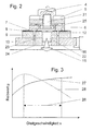
- Fig. 2
- einen Bereich II in Fig. 1 in vergrößerter Ansicht und
- Fig. 3
- den Verlauf von Reibwertcharakteristiken.
It shows:
- Fig. 1
- schematically a structure of a device according to the invention;
- Fig. 2
- an area II in Fig. 1 in an enlarged view and
- Fig. 3
- the course of the coefficient of friction characteristics.
Ein Motor 1 treibt über eine Drehmomentmeßnabe 2, eine
Antriebswelle 4 und eine Ausgleichsverbindung 3 eine Stützscheibe
5 an, an der mit einer Schraube 22 eine Ringscheibe
6 befestigt ist. Die Ringscheibe 6 bildet einen Reibpartner
und besitzt eine Ringfläche 7, mit der sie an einem
anderen Reibpartner anliegt. Dieser wird von einem Reibbelag
8 gebildet, der auf einen Grundkörper 9 aufgebracht
ist. Der Grundkörper 9 ist mittels einer Schraube 21 mit
einem Probenhalter 10 verschraubt, der in einem Prüfbehälter
14 über eine Momentenabstützung 16 drehfest gehalten
ist und über ein Spitzenlager 11 nach allen Seiten hin
kippbeweglich gelagert ist. Anstelle des Spitzenlagers 11,
das von einem doppelkegelförmigen Körper gebildet wird,
kann auch eine Kugel verwendet werden, die in entsprechende
Kalotten der benachbarten Teile eingreift.A
Der Prüfbehälter 14 ist doppelwandig und kann temperiert
werden, so daß Schmieröle und Reibpaarungen bei verschiedenen
Betriebstemperaturen untersucht werden können.
Er ist bis zu einem mit 13 bezeichneten Ölspiegel mit Prüföl
gefüllt.The
Der Prüfbehälter 14 ruht auf einem Prüftisch 15. Ein
Lastaufgabesystem 20 drückt den Prüftisch 15 mit dem Probenhalter
10, dem Grundkörper 9 und dem Reibbelag 8 über
einen Hebelmechanismus 18, der sich an einem Fundament 19
gelenkig abstützt, gegen die Ringfläche 7 der Ringscheibe
6.The
Das erfindungsgemäße Verfahren wird wie folgt durchgeführt: The process according to the invention is carried out as follows:
Die beiden Reibpartner, die von der Ringscheibe 6 einerseits
und dem Grundkörper 9 mit dem Reibbelag 8 andererseits
gebildet werden, werden aufgespannt und der Prüfbehälter
14 mit dem zu untersuchenden Prüföl gefüllt. Die
beiden Reibpartner entsprechen im wesentlichen den in der
Praxis verwendeten Reibpaarungen. Um Reibpaarungen auf ihre
Langzeittauglichkeit zu prüfen, verwendet man als Prüföl
ein bewährtes Öl mit bekannten Eigenschaften.The two friction partners on the one hand from the
Es folgt der Abgleich der Meßwertaufnehmer. Um die
Normalkraft zu messen, ist eine Kraftmeßeinrichtung 17 im
Kraftfluß integriert, z. B. wie in Fig. 1 gezeigt zwischen
dem Hebelmechanismus 18 und dem Prüftisch 15. Die Reibkraft
wird mittels Meßstreifen an der Momentenabstützung 16 ermittelt.
Das Antriebsmoment des Motors 1, der von einem
externen Sollwertgeber auf eine vorgegebene Solldrehzahl
geregelt wird, kann mittels der Drehmomentmeßnabe 2 erfaßt
und alternativ, wenn auch mit einer größeren Ungenauigkeit,
zur Ermittlung der Reibkraft verwendet werden. Danach wird
die Prüflast aufgebracht, die sich aufgrund des Spitzenlagers
11 und er Ausgleichsverbindung 3 gleichmäßig auf die
Ringfläche 7 verteilt.The transducers are then compared. To the
To measure normal force is a
Mit einem doppelwandigen, temperierbaren Gefäß als
Prüfbehälter 14 wird die Prüftemperatur eingeregelt, wozu
ein nicht dargestellter Temperaturfühler im Prüfbehälter 14
dient. Ist die Prüftemperatur erreicht, kann der Einlaufvorgang
zur Formierung der Reibflächen an der Ringfläche 7
und am Reibbelag 8 gestartet werden. Daran schließt sich
der eigentliche Prüfzyklus an, wobei eine Meßreihe mit mehreren
Gleitgeschwindigkeiten durchgeführt wird, die durch
die Solldrehzahl des Motors 1 vorgegeben werden. Der Reibwert
wird rechnerisch aus dem Verhältnis der Reibkraft zur
Normalkraft ermittelt.With a double-walled, temperature-controlled vessel as
Fig. 3 zeigt ein Schaubild mit zwei Reibwertcharakteristiken
27 und 28. Verläuft die Reibwertcharakteristik 27
in einem Betriebsbereich 26 progressiv, ist das Schmiermittel
für den Einsatz in schlupfgeregelten Kupplungen geeignet.
Fällt jedoch die Reibwertcharakteristik 28 im Betriebsbereich
26 degressiv ab, ist im Fahrzeugeinsatz mit
selbsterregten Reibschwingungen zu rechnen, so daß das
Schmiermittel für diesen Einsatzfall nicht geeignet ist.3 shows a diagram with two
Um zu vermeiden, daß sich das Prüföl unter der Ringscheibe
6 überhitzt, sondern gleichmäßig temperiert bleibt,
sind im Probenhalter 10 und im Grundkörper 9 sowie in der
Ringscheibe 6 und der Stützscheibe 5 Ölkanäle 12 vorgesehen,
durch die das Prüföl in Richtung der Pfeile 23 von
einem Öleintritt 24 zu einem Ölaustritt 25 befördert wird.
Die Förderwirkung wird durch Zentrifugalkraft in den im
wesentlichen radial verlaufenden Teilstücken der rotierenden
Ölkanäle 12 erzeugt.To avoid that the test oil is under the
Aufgrund des einfachen Aufbaus und der geringen Prüfölmenge, die für eine Meßwertreihe erforderlich ist, kann der Aufwand für die Messungen über einen Lebensdauerzyklus in vertretbaren Grenzen gehalten werden. Die geringe Prüfölentnahme erlaubt, daß Dauerversuche ohne Beeinträchtigung fortgeführt werden können, so daß man aussagekräftige Meßergebnisse für den gesamten Lebensdauerzyklus erhält. Due to the simple structure and the small amount of test oil, which is required for a series of measured values the effort for the measurements over a life cycle be kept within reasonable limits. The low test oil withdrawal allowed endurance trials without interference can be continued so that you get meaningful measurement results for the entire life cycle.
- 11
- Motorengine
- 22
- Drehmomentmeßnabetorque measurement
- 33
- Ausgleichsverbindungequalizing connection
- 44
- Antriebswelledrive shaft
- 55
- Stützscheibesupport disc
- 66
- Ringscheibewasher
- 77
- Ringflächering surface
- 88th
- Reibbelagfriction lining
- 99
- Grundkörperbody
- 1010
- Probenhaltersample holder
- 1111
- Spitzenlagertoe bearing
- 1212
- Ölkanäleoil passages
- 1313
- Ölspiegeloil level
- 1414
- PüfbehälterPüfbehälter
- 1515
- Prüftischtest table
- 1616
- Momentenabstützungtorque support
- 1717
- Kraftmeßeinrichtungforce measuring device
- 1818
- Hebelmechanismuslever mechanism
- 1919
- Fundamentfoundation
- 2020
- LastaufgabesystemLast Injection System
- 2121
- Schraubescrew
- 2222
- Schraubescrew
- 2323
- Pfeilearrows
- 2424
- Öleintrittoil inlet
- 2525
- Ölaustrittoil spill
- 2626
- Betriebsbereichoperating range
- 2727
- Reibwertcharakteristikfriction control
- 2828
- Reibwertcharakteristikfriction control
- 2929
- Verdrängerkörperdisplacement
Claims (8)
- Process for determining the functioning capability of lubricating oils for slip-regulated clutches, the said process comprising the following steps:characterised in that, for performing the said method, use is made of a device in which a specimen-holder (10) is mounted in the test receptacle (14) so as to be pivotable on a conical (11) or ball bearing in a torsion-proof manner, which specimen-holder carries a basic body (9) with a first friction partner (8) against which a second friction partner in the form of an annular disc (6) rests via a defined annular face (7), the said second friction partner (6) being driven by a motor (1), and a load-assigning system (20) pressing the test receptacle (14) with the first friction partner (8) against the second friction partner (6, 7).two friction partners (6, 8) are mounted and placed in a test receptacle (14) filled with test oil,transducers for a normal force (17) and a friction force are balanced,one friction partner (6, 7) is driven while the other friction partner (8) stands still,a normal force is applied as a test load,after a predetermined test temperatures has been reached, a running-in operation is started for the purpose of forming the test faces of the friction partners (6, 8),various speed stages are set by means of suitable rotational driving speeds and maintained until a stable condition sets in, andthe friction force and normal force are then determined and the friction value calculated therefrom,
- Process according to claim 1, characterised in that the quantity of test oil is limited to a quantity of less than 200 ml.
- Process according to claim 1 or 2, characterised in that displacer bodies (29) are disposed in the test receptacle (14),
- Device for performing the process according to one of the preceding claims, characterised in thata specimen-holder (10) is mounted in the test receptacle, which is disposed in a torsion-proof manner, so as to be pivotable on a conical (11) or ball bearing in a torsion-proof manner, which specimen-holder carries a basic body (9) with a first friction partner (8) against which a second friction partner in the form of an annular disc (6) rests via a defined annular face (7), the said second friction partner (6) being driven by a motor (1), and a load-assigning system (20) pressing the test receptacle (14) with the first friction partner (8) against the second friction partner (6, 7),that a transducer for the normal force (17) and the friction force (2, 16), and a transducer for the test temperature are provided, andthat various rotational driving speeds can be set at the driving motor (1).
- Device according to claim 4, characterised in that the test receptacle (14) is a double-wall, temperable vessel.
- Device according to claim 4 or 5, characterised in that a force-measuring apparatus (17) is disposed between the load-assigning system (20) and the test receptacle (14).
- Device according to one of the preceding claims 4 to 6, characterised in that the friction force at the moment-supporting device (16) is detected by means of strain gauges.
- Device according to one of the preceding claims 4 to 7, characterised in that there are provided, in the specimen-holder (10) and basic body (9) and also in the annular disc (6) and supporting disc (5), oil ducts (12) which connect an oil entry (24) to an oil exit (25) and through which test oil is conveyed, as a result of centrifugal force, in rotating, radially extending sections of the said oil ducts (12).
Applications Claiming Priority (3)
| Application Number | Priority Date | Filing Date | Title |
|---|---|---|---|
| DE19644029 | 1996-10-31 | ||
| DE19644029A DE19644029A1 (en) | 1996-10-31 | 1996-10-31 | Procedure for determining the functionality of lubricating oils |
| PCT/EP1997/005904 WO1998019157A1 (en) | 1996-10-31 | 1997-10-25 | Process for determining the lubricant power of lubricant oils |
Publications (2)
| Publication Number | Publication Date |
|---|---|
| EP0935751A1 EP0935751A1 (en) | 1999-08-18 |
| EP0935751B1 true EP0935751B1 (en) | 2002-01-09 |
Family
ID=7809748
Family Applications (1)
| Application Number | Title | Priority Date | Filing Date |
|---|---|---|---|
| EP97913178A Expired - Lifetime EP0935751B1 (en) | 1996-10-31 | 1997-10-25 | Process for determining the lubricant power of lubricant oils |
Country Status (5)
| Country | Link |
|---|---|
| US (1) | US6112573A (en) |
| EP (1) | EP0935751B1 (en) |
| JP (1) | JP2001502807A (en) |
| DE (2) | DE19644029A1 (en) |
| WO (1) | WO1998019157A1 (en) |
Families Citing this family (15)
| Publication number | Priority date | Publication date | Assignee | Title |
|---|---|---|---|---|
| US5969227A (en) * | 1998-01-30 | 1999-10-19 | Newpark Drilling Fluids, Inc. | Apparatus and method for testing lubricity |
| DE10030854B4 (en) * | 2000-06-23 | 2010-12-16 | Volkswagen Ag | Method for determining and / or detecting the current state of a lubricant |
| DE10116760A1 (en) * | 2001-04-04 | 2002-10-17 | Bayer Ag | Device and method for determining a coefficient of friction |
| GB0500124D0 (en) * | 2005-01-06 | 2005-02-09 | Ici Plc | Tribology apparatus and method |
| US8695398B2 (en) * | 2011-03-25 | 2014-04-15 | Fred M. Johnson | Intrinsically-calibrated tribometer |
| US9194784B1 (en) * | 2012-07-26 | 2015-11-24 | Hongfeng Bi | High pressure, high temperature lubricity tester |
| US9528974B2 (en) * | 2013-10-11 | 2016-12-27 | Baker Hughes Incorporated | Friction apparatus and method for measuring lubricity of downhole fluids |
| CN105572325B (en) * | 2014-04-21 | 2017-06-23 | 北京雅士科莱恩石油化工有限公司 | A kind of frictional testing machine for test evaluation anti-wear and wear-resistant performance |
| DE102014213219B4 (en) | 2014-07-08 | 2023-08-31 | Zf Friedrichshafen Ag | Arrangement for testing components |
| DE102017118902A1 (en) * | 2017-08-18 | 2019-02-21 | Technische Universität Darmstadt | Test specimen holder and a system for investigating a friction behavior |
| KR102076258B1 (en) * | 2018-01-05 | 2020-02-11 | 경북대학교 산학협력단 | Apparatus for testing lubricating characteristics of liquid metal |
| WO2019226177A1 (en) * | 2018-05-25 | 2019-11-28 | Halliburton Energy Services, Inc. | Testing wear resistance in representative downhole conditions |
| JP7156903B2 (en) * | 2018-10-26 | 2022-10-19 | Kyb株式会社 | Lubricant evaluation method |
| CN110865024A (en) * | 2019-11-16 | 2020-03-06 | 佛山市铂索润滑材料有限公司 | Metal cutting fluid performance testing equipment and using method |
| CN113777025B (en) * | 2021-07-30 | 2023-10-31 | 军事科学院系统工程研究院军事新能源技术研究所 | Gear oil friction characteristic evaluation method |
Family Cites Families (11)
| Publication number | Priority date | Publication date | Assignee | Title |
|---|---|---|---|---|
| DE8428779U1 (en) * | 1985-01-03 | Reiner Chemische Fabrik GmbH & Co, 6751 Weilerbach | Testing machine | |
| US2909056A (en) * | 1958-05-20 | 1959-10-20 | George L Neely | Kinetic oiliness testing machine |
| US3045471A (en) * | 1958-08-28 | 1962-07-24 | Pure Oil Co | Method and apparatus for testing lubricants |
| US3913377A (en) * | 1973-12-17 | 1975-10-21 | Sun Oil Co Pennsylvania | Friction testing machine for lubricants |
| FR2277342A1 (en) * | 1974-07-04 | 1976-01-30 | France Etat | Test device for liquid or solid lubricants - measures frictional forces between rotating disc and second piece with lubricant between |
| DE2831158C2 (en) * | 1978-07-15 | 1985-02-14 | Skf Kugellagerfabriken Gmbh, 8720 Schweinfurt | Device for determining the properties of a lubricant |
| DE8428799U1 (en) * | 1984-09-29 | 1985-02-14 | Engel, Sabine | VACUUM, WET, AND SPRAY EXTRACTORS |
| SU1511635A1 (en) * | 1987-07-13 | 1989-09-30 | Таджикский политехнический институт | Friction machine for assessing the lubricating ability of lubricants of friction pair |
| DD265693A1 (en) * | 1987-11-04 | 1989-03-08 | Zwickau Ing Hochschule | DEVICE FOR DETERMINING THE FRICTION AND WEAR BEHAVIOR OF MATERIALS AND LUBRICANTS |
| DE3933973A1 (en) * | 1989-10-11 | 1991-04-18 | Augustin Hans Ulrich | Measuring lubrication capability of lubricant, esp. for vehicle - by measuring pressure on two surfaces moved w.r.t. each other with test substance between them |
| DD301700A9 (en) * | 1990-03-01 | 1993-07-15 | Gerfema Ges Fuer Forschung U R | DEVICE FOR MEASURING THE FRICTION AND WEAR BEHAVIOR OF TWO FRICTION BODIES |
-
1996
- 1996-10-31 DE DE19644029A patent/DE19644029A1/en not_active Ceased
-
1997
- 1997-10-25 JP JP10520031A patent/JP2001502807A/en active Pending
- 1997-10-25 US US09/284,356 patent/US6112573A/en not_active Expired - Fee Related
- 1997-10-25 WO PCT/EP1997/005904 patent/WO1998019157A1/en active IP Right Grant
- 1997-10-25 EP EP97913178A patent/EP0935751B1/en not_active Expired - Lifetime
- 1997-10-25 DE DE59706134T patent/DE59706134D1/en not_active Expired - Fee Related
Also Published As
| Publication number | Publication date |
|---|---|
| DE59706134D1 (en) | 2002-02-28 |
| US6112573A (en) | 2000-09-05 |
| DE19644029A1 (en) | 1998-05-07 |
| WO1998019157A1 (en) | 1998-05-07 |
| EP0935751A1 (en) | 1999-08-18 |
| JP2001502807A (en) | 2001-02-27 |
Similar Documents
| Publication | Publication Date | Title |
|---|---|---|
| EP0935751B1 (en) | Process for determining the lubricant power of lubricant oils | |
| DE102006060922B4 (en) | Measurement of torque uniformity on multi-disc clutches | |
| DE3612038C2 (en) | ||
| DE4328537C2 (en) | Transmission test bench and method for testing a transmission | |
| EP3625532B1 (en) | Test bench arrangement for testing a multi-plate clutch | |
| DE10059450A1 (en) | Variator slip detection method for continuously variable transmission uses detection and analysis of vibration noise | |
| DE19851160A1 (en) | Arrangement for controlling automatic gearbox has electronic controller of gearbox coupling changing pressure or gearbox variator application pressure as function of engine torque | |
| EP1899631B1 (en) | Method and device for monitoring operational reliability of a drive which transmits torque by means of frictional engagement | |
| Ohtani et al. | Prediction of anti-shudder properties of automatic transmission fluids using a modified SAE No. 2 machine | |
| DE60303694T2 (en) | Tribological test device | |
| DE2645902B2 (en) | Device for friction and wear testing of material samples | |
| DE2904060C2 (en) | Method for relubricating a roller bearing of an electric motor that has been lubricated with grease | |
| DE3535103C2 (en) | ||
| EP1931890B1 (en) | Life usage tracking system | |
| DE10228216A1 (en) | Device for detecting a torque in a transmission | |
| Rodgers et al. | Friction of transmission clutch materials as affected by fluids, additives, and oxidation | |
| DE3905333A1 (en) | DEVICE AND METHOD FOR TESTING SYNCHRONIZING UNITS | |
| DE2811809C2 (en) | Transmitter for measuring angles of rotation between two measuring points of a machine element transmitting a torque | |
| Smith et al. | Putting automatic transmission clutch friction researchers on speaking terms | |
| US4152927A (en) | Viscosity simulator | |
| DE10030854B4 (en) | Method for determining and / or detecting the current state of a lubricant | |
| McCord | Gylon friction material for transmission synchronizers | |
| DE102015221208B4 (en) | Method and reference device for calibrating a measuring device | |
| Thorp | A novel tri-pin-on-disc tribometer designed to retain lubricants | |
| DE19720325C1 (en) | Method and apparatus for measuring reactive forces in machine drives |
Legal Events
| Date | Code | Title | Description |
|---|---|---|---|
| PUAI | Public reference made under article 153(3) epc to a published international application that has entered the european phase |
Free format text: ORIGINAL CODE: 0009012 |
|
| 17P | Request for examination filed |
Effective date: 19990204 |
|
| AK | Designated contracting states |
Kind code of ref document: A1 Designated state(s): DE FR GB |
|
| GRAG | Despatch of communication of intention to grant |
Free format text: ORIGINAL CODE: EPIDOS AGRA |
|
| GRAG | Despatch of communication of intention to grant |
Free format text: ORIGINAL CODE: EPIDOS AGRA |
|
| GRAH | Despatch of communication of intention to grant a patent |
Free format text: ORIGINAL CODE: EPIDOS IGRA |
|
| 17Q | First examination report despatched |
Effective date: 20010525 |
|
| GRAH | Despatch of communication of intention to grant a patent |
Free format text: ORIGINAL CODE: EPIDOS IGRA |
|
| GRAA | (expected) grant |
Free format text: ORIGINAL CODE: 0009210 |
|
| REG | Reference to a national code |
Ref country code: GB Ref legal event code: IF02 |
|
| AK | Designated contracting states |
Kind code of ref document: B1 Designated state(s): DE FR GB |
|
| REF | Corresponds to: |
Ref document number: 59706134 Country of ref document: DE Date of ref document: 20020228 |
|
| GBT | Gb: translation of ep patent filed (gb section 77(6)(a)/1977) |
Effective date: 20020406 |
|
| ET | Fr: translation filed | ||
| PLBE | No opposition filed within time limit |
Free format text: ORIGINAL CODE: 0009261 |
|
| STAA | Information on the status of an ep patent application or granted ep patent |
Free format text: STATUS: NO OPPOSITION FILED WITHIN TIME LIMIT |
|
| 26N | No opposition filed | ||
| PG25 | Lapsed in a contracting state [announced via postgrant information from national office to epo] |
Ref country code: FR Free format text: LAPSE BECAUSE OF NON-PAYMENT OF DUE FEES Effective date: 20030630 |
|
| REG | Reference to a national code |
Ref country code: FR Ref legal event code: ST |
|
| PGFP | Annual fee paid to national office [announced via postgrant information from national office to epo] |
Ref country code: GB Payment date: 20051019 Year of fee payment: 9 |
|
| PGFP | Annual fee paid to national office [announced via postgrant information from national office to epo] |
Ref country code: DE Payment date: 20051020 Year of fee payment: 9 |
|
| PG25 | Lapsed in a contracting state [announced via postgrant information from national office to epo] |
Ref country code: DE Free format text: LAPSE BECAUSE OF NON-PAYMENT OF DUE FEES Effective date: 20070501 |
|
| GBPC | Gb: european patent ceased through non-payment of renewal fee |
Effective date: 20061025 |
|
| PG25 | Lapsed in a contracting state [announced via postgrant information from national office to epo] |
Ref country code: GB Free format text: LAPSE BECAUSE OF NON-PAYMENT OF DUE FEES Effective date: 20061025 |