EP0935744B1 - Gerät und methode zur bestimmung der verteilungs- und durchflusseigenschaften einer einspritzdüse - Google Patents
Gerät und methode zur bestimmung der verteilungs- und durchflusseigenschaften einer einspritzdüse Download PDFInfo
- Publication number
- EP0935744B1 EP0935744B1 EP97910759A EP97910759A EP0935744B1 EP 0935744 B1 EP0935744 B1 EP 0935744B1 EP 97910759 A EP97910759 A EP 97910759A EP 97910759 A EP97910759 A EP 97910759A EP 0935744 B1 EP0935744 B1 EP 0935744B1
- Authority
- EP
- European Patent Office
- Prior art keywords
- nozzle
- fluid
- piezoelectric film
- film sensors
- sensing surface
- Prior art date
- Legal status (The legal status is an assumption and is not a legal conclusion. Google has not performed a legal analysis and makes no representation as to the accuracy of the status listed.)
- Expired - Lifetime
Links
- 238000002347 injection Methods 0.000 title claims abstract description 27
- 239000007924 injection Substances 0.000 title claims abstract description 27
- 238000000034 method Methods 0.000 title claims description 16
- 238000009826 distribution Methods 0.000 title description 6
- 239000012530 fluid Substances 0.000 claims abstract description 20
- 230000003116 impacting effect Effects 0.000 claims abstract description 9
- 230000004907 flux Effects 0.000 claims description 11
- 239000007921 spray Substances 0.000 claims description 10
- 239000007788 liquid Substances 0.000 claims description 3
- 238000007599 discharging Methods 0.000 claims 1
- 239000010408 film Substances 0.000 description 29
- 239000000446 fuel Substances 0.000 description 19
- 239000002033 PVDF binder Substances 0.000 description 4
- 239000003595 mist Substances 0.000 description 4
- 229920002981 polyvinylidene fluoride Polymers 0.000 description 4
- 238000000576 coating method Methods 0.000 description 3
- 238000010276 construction Methods 0.000 description 3
- 238000004519 manufacturing process Methods 0.000 description 3
- 238000003908 quality control method Methods 0.000 description 3
- 238000006243 chemical reaction Methods 0.000 description 2
- 238000002485 combustion reaction Methods 0.000 description 2
- 230000006835 compression Effects 0.000 description 2
- 238000007906 compression Methods 0.000 description 2
- 230000000694 effects Effects 0.000 description 2
- 238000007689 inspection Methods 0.000 description 2
- 239000000463 material Substances 0.000 description 2
- 238000005259 measurement Methods 0.000 description 2
- 230000002123 temporal effect Effects 0.000 description 2
- 238000012360 testing method Methods 0.000 description 2
- 108010014172 Factor V Proteins 0.000 description 1
- 229910000831 Steel Inorganic materials 0.000 description 1
- 239000000853 adhesive Substances 0.000 description 1
- 230000001070 adhesive effect Effects 0.000 description 1
- 238000003491 array Methods 0.000 description 1
- 230000015572 biosynthetic process Effects 0.000 description 1
- 239000011248 coating agent Substances 0.000 description 1
- 238000004891 communication Methods 0.000 description 1
- 238000011161 development Methods 0.000 description 1
- 239000007772 electrode material Substances 0.000 description 1
- 230000002708 enhancing effect Effects 0.000 description 1
- 229920006333 epoxy cement Polymers 0.000 description 1
- 230000003993 interaction Effects 0.000 description 1
- 238000009533 lab test Methods 0.000 description 1
- 238000003754 machining Methods 0.000 description 1
- 239000002985 plastic film Substances 0.000 description 1
- 229920006255 plastic film Polymers 0.000 description 1
- 238000012545 processing Methods 0.000 description 1
- 239000010959 steel Substances 0.000 description 1
- 239000000758 substrate Substances 0.000 description 1
- 238000010998 test method Methods 0.000 description 1
- 239000010409 thin film Substances 0.000 description 1
- 238000011179 visual inspection Methods 0.000 description 1
Images

Classifications
-
- F—MECHANICAL ENGINEERING; LIGHTING; HEATING; WEAPONS; BLASTING
- F02—COMBUSTION ENGINES; HOT-GAS OR COMBUSTION-PRODUCT ENGINE PLANTS
- F02D—CONTROLLING COMBUSTION ENGINES
- F02D41/00—Electrical control of supply of combustible mixture or its constituents
- F02D41/24—Electrical control of supply of combustible mixture or its constituents characterised by the use of digital means
- F02D41/26—Electrical control of supply of combustible mixture or its constituents characterised by the use of digital means using computer, e.g. microprocessor
- F02D41/28—Interface circuits
-
- F—MECHANICAL ENGINEERING; LIGHTING; HEATING; WEAPONS; BLASTING
- F02—COMBUSTION ENGINES; HOT-GAS OR COMBUSTION-PRODUCT ENGINE PLANTS
- F02M—SUPPLYING COMBUSTION ENGINES IN GENERAL WITH COMBUSTIBLE MIXTURES OR CONSTITUENTS THEREOF
- F02M65/00—Testing fuel-injection apparatus, e.g. testing injection timing ; Cleaning of fuel-injection apparatus
-
- G—PHYSICS
- G01—MEASURING; TESTING
- G01F—MEASURING VOLUME, VOLUME FLOW, MASS FLOW OR LIQUID LEVEL; METERING BY VOLUME
- G01F1/00—Measuring the volume flow or mass flow of fluid or fluent solid material wherein the fluid passes through a meter in a continuous flow
- G01F1/05—Measuring the volume flow or mass flow of fluid or fluent solid material wherein the fluid passes through a meter in a continuous flow by using mechanical effects
- G01F1/34—Measuring the volume flow or mass flow of fluid or fluent solid material wherein the fluid passes through a meter in a continuous flow by using mechanical effects by measuring pressure or differential pressure
-
- G—PHYSICS
- G01—MEASURING; TESTING
- G01F—MEASURING VOLUME, VOLUME FLOW, MASS FLOW OR LIQUID LEVEL; METERING BY VOLUME
- G01F1/00—Measuring the volume flow or mass flow of fluid or fluent solid material wherein the fluid passes through a meter in a continuous flow
- G01F1/76—Devices for measuring mass flow of a fluid or a fluent solid material
- G01F1/78—Direct mass flowmeters
- G01F1/80—Direct mass flowmeters operating by measuring pressure, force, momentum, or frequency of a fluid flow to which a rotational movement has been imparted
-
- F—MECHANICAL ENGINEERING; LIGHTING; HEATING; WEAPONS; BLASTING
- F02—COMBUSTION ENGINES; HOT-GAS OR COMBUSTION-PRODUCT ENGINE PLANTS
- F02D—CONTROLLING COMBUSTION ENGINES
- F02D2200/00—Input parameters for engine control
- F02D2200/02—Input parameters for engine control the parameters being related to the engine
- F02D2200/06—Fuel or fuel supply system parameters
- F02D2200/0614—Actual fuel mass or fuel injection amount
-
- F—MECHANICAL ENGINEERING; LIGHTING; HEATING; WEAPONS; BLASTING
- F02—COMBUSTION ENGINES; HOT-GAS OR COMBUSTION-PRODUCT ENGINE PLANTS
- F02D—CONTROLLING COMBUSTION ENGINES
- F02D2250/00—Engine control related to specific problems or objectives
- F02D2250/16—End position calibration, i.e. calculation or measurement of actuator end positions, e.g. for throttle or its driving actuator
Definitions
- This invention relates generally to a test apparatus and method for determining the spatial, temporal and mass flow rate distribution of a fluid discharged through an injection nozzle, and more particularly to such an apparatus and method using an array of pressure sensors to sense the momentum of fluid impacting on each sensor.
- Japanese Publication Number 02-130260 entitled “Inspection of Mist Injection Characteristic” describes a pressure sensing device for measuring pressure of mist from an injection nozzle. A number of discrete piezoelectric sensors are placed proximate to the mist.
- the invention relates to an apparatus as claimed in claim 1 and to a method as claimed in claim 3.
- the apparatus and method provide quantitative measurement of total flow characteristics from a nozzle.
- a plurality of piezoelectric film sensors are arranged in a predefined spatial array in spaced relationship with the nozzle.
- Each of the piezoelectric sensors is adapted to deliver an electrical signal proportional to the instantaneous momentum of fluid impacting on that sensor.
- the sensor array is arranged relative to the nozzle such that the combination of the piezoelectric film sensors forms a substantially continuous sensing surface normal to the direction of spray from the nozzle.
- the area of the sensing surface is at least as large as the area of spray from the nozzle, such that substantially all of the liquid impacts on the sensing surface.
- the invention further has a means for receiving said electrical signal from each of said piezoelectric film sensors and calculating the total instantaneous momentum flux of substantially all of the liquid instantaneously impacting on the sensing surface.
- an apparatus 10 includes an atmospheric, i.e., open topped, pressure spray chamber 12, having a drain 14 at the bottom associated with a conventional fuel-air separator, not shown, and an exhaust fan 16 .
- a porous, honeycomb flow straightener 18 is positioned across the open top of the chamber 12 to provide a laminar flow of air through the chamber, thereby enhancing the removal of fuel mist and vapor from the chamber and minimizing the effect of air movement on a fuel jet 20 emanating from the ports of a fuel injector 22 mounted in the chamber 12.
- a web-type support bracket 24 is adapted to removably support the fuel injector 22, for example by a threaded holder, at a predetermined position within the chamber 12 .
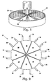
- the fuel injector 22 shown schematically in Fig. 3 has a single hole, or port, located on the centerline of the tip of the injector 22.
- the sensor array 26 is mounted on a support 30 connected to a two-dimensional indexing assembly 32 that is used to accurately position the sensor array 26 in a plane perpendicular to the centerline of the spray jet and the nozzle tip.
- a three-dimensional traversing, or positioning, assembly may be used to further vary the position the array 26 with respect to the injector to allow for variation in symmetry of the spray pattern.
- the injection nozzle is connected to a conventional electric motor driven injection pump that is in fluid communication with a source of the fluid to be used in determining the particular distribution and flow characteristics of the injector 22.
- the apparatus 10 may also be equipped with a linear transducer for measurement of the instantaneous position of the needle in the injector's nozzle valve, and a pressure transducer for measuring the injection pressure, i.e., the fluid pressure at the inlet to the injector 22.
- the sensors 28 are preferably formed of a piezoelectric sheet film material, such as polyvinylidene fluoride (PVDF) piezoelectric film produced by AMP Corp, Inc.
- PVDF polyvinylidene fluoride
- the PVDF piezoelectric film has a thickness of about 28 ⁇ m.
- the circular sensor array 26, comprising eight separate sensors 28 shaped as wedges or segments, is illustrated in Fig. 2 and has a diameter of about 22.2 mm, thereby providing each sensor with a surface area of about 8.7 mm 2 .
- the electrodes are only applied to the top and bottom surfaces of the film so the electrical axis of the film is always normal to the mounting surface. While the entire film is piezoelectric-electric, the actual sensing area is that part of the film that is coated with electrode material.
- the coating must be applied to both sides of the film which may be conveniently carried out using techniques similar to the formation of circuits on printed circuit boards and thin film substrates.
- the sensing area is defined by the areas where the coatings overlap, i.e., are disposed on both the top and bottom surface.
- the electrical connections to the film are generally made at the edges of the film where the coatings on both surfaces are extended and a mechanical wire attachment is made. These "lead outs" do not overlap each other and, therefore, do not add sensor area.
- the sensor array 26 is preferably mounted to a rigid backing member, such as a steel plate, so that the film is always fully constrained and therefore responds to compression in thickness. Also, rigid backing of the film reduces delay in response to impact of fuel on the film.
- the attachment of the sensor array 26 to the rigid backing may be conveniently accomplished by a suitable adhesive material, such as epoxy cement.
- equation (5) can be used directly to calculate the instantaneous momentum flux M dot for each sensor 28.
- These instantaneous values can be integrated over all of the sensors 28 in the array 26 to give the total instantaneous momentum flux within the jet.
- the total momentum flux of the jet can be computed by integrating the total instantaneous momentum over the time of injection.
- the value of the specific mass flow at each position can be identified. By adding together the mass flow of all of the sensors 28 at a specific point in time, the total instantaneous mass flow of the injector 22 can be easily determined.
- a PC based data acquisition system 40 shown schematically in Fig. 4, includes a 483-33 PC equipped with a National Instrument 16 channel multiplexed A-D board capable of a total data through-put rates of 100 kHz. Labview virtual instrument software is used to control the data acquisition process and to reduce the data to the appropriate mechanical units.
- the input impedance of the data acquisition system 40 is too low for direct conversion of the sensor 28 outputs.
- a signal conversion circuit 38 comprising a 1NA110 operational amplifier, disposed between the sensors 28 and the data acquisition system 40, is used to match the output requirement of the film with the input requirements of the data acquisition system 40.
- the resultant system has a frequency response of 16 kHz.
- the analog signal from the sensors 28 is thus delivered to the data acquisition system 40 whereat the analog signals are converted to digital values by the A-D board of the system, which provides a value for use by the system in the calculation of the instantaneous mass flow rate.
- the sensors 28 be substantially symmetrically positioned with respect to the discharge ports of the injector 22, and that the pressure-sensing surface of each sensor 28 be positioned substantially perpendicular to the axis of the radiated jet stream. Likewise, in multiple array arrangements, it is desirable that each sensor 28 within an array have substantially equal surface areas to negate the effect of varying force-sensing surface areas.
- a cylindrical array 26 of sensors 28 is symmetrically spaced, coaxially with the centerline of the injector 22, about the injector tip.
- the cylindrical array 26 has a height, or length, along its longitudinal axis that is greater than the height of the fuel plumes 20, and each of the sensors 28 is much smaller than the width of the plume 20.
- the output voltage of each sensor 28 is individually detected and used to provide spatial resolution of the force imparted.
- the mass flux distribution across each of the individual plumes, or jets, 20 can also be determined.
- the sensors 28 may be arranged in groups of eight to form an array 26 as shown in fig. 2, and a plurality of the eight-sensor arrays 26 spatially arranged to provide sensors that are desirably positioned at defined optimum impact areas for each individual jet of an injector nozzle.
- the apparatus 10 and method embodying the present invention is particularly useful for measuring the instantaneous injection rate and the fuel distribution with individual plumes discharged from an injection nozzle.
- the signal from each sensor 28 can be integrated over area to determine the overall injection rate, and integrated over time to arrive at the total quantity of fuel injected.
- the apparatus 10 and method embodying the present invention also provides an easily automated quality control tool during the manufacture of injection nozzles to monitor various machining processes and assure compliance with predefined performance standards.
Landscapes
- Engineering & Computer Science (AREA)
- Chemical & Material Sciences (AREA)
- General Physics & Mathematics (AREA)
- Fluid Mechanics (AREA)
- Physics & Mathematics (AREA)
- Combustion & Propulsion (AREA)
- Mechanical Engineering (AREA)
- General Engineering & Computer Science (AREA)
- Computer Hardware Design (AREA)
- Microelectronics & Electronic Packaging (AREA)
- Measuring Volume Flow (AREA)
- Jet Pumps And Other Pumps (AREA)
- Fuel-Injection Apparatus (AREA)
Claims (5)
- Vorrichtung (10) zum Bestimmen der Gesamtströmungseigenschaften eines Fluids (20), das aus einer Mehrfachstrahl-Einspritzdüse (22) ausgestoßen wird, wobei die Vorrichtung (10) aufweist:wobei die räumliche Anordnung (26) in Bezug auf die Düse (22) so angeordnet ist, dass die Kombination der piezoelektrischen Foliensensoren (28) eine im Wesentlichen zusammenhängende Sensoroberfläche normal zur Sprührichtung aus der Düse (22) bildet;eine Anzahl von piezoelektrischen Foliensensoren (28), die in einer vorgegebenen räumlichen Anordnung (26) in beabstandeter Beziehung zu der Düse (22) angeordnet sind, wobei jeder der piezoelektrischen Foliensensoren (28) so gestaltet ist, dass er ein elektrisches Signal abgibt, das proportional zum jeweiligen Impuls des Fluids (20) ist, das auf jeweils einen der piezoelektrischen Foliensensoren (28) auftrifft;
wobei das Gebiet der Sensoroberfläche zumindest so groß wie die Sprühfläche von der Düse (22) ist, so dass im Wesentlichen das gesamte Fluid (20) auf die Sensoroberfläche auftrifft; und
ein Mittel (38, 40) zum Aufnehmen des elektrischen Signals von jedem der piezoelektrischen Foliensensoren (28) und zum Berechnen des gesamten augenblicklichen Impulsflusses von im Wesentlichen dem gesamten Fluid (20), das in jedem Augenblick auf die Sensoroberfläche auftrifft. - Vorrichtung (10) nach Anspruch 1, wobei das Mittel (40) zum Aufnehmen der elektrischen Signale von jedem der Sensoren (28) einen Analog/Digital-Signalwandler (38) und einen programmierbaren Computer (40) aufweist.
- Verfahren zum Bestimmen der Gesamtströmungseigenschaften eines Fluids (20), das in einer Anzahl von Strahlen aus einer Einspritzdüse (22) ausgestoßen wird, mit den Schritten:wobei die räumliche Anordnung (26) in Bezug auf die Düse (22) so angeordnet ist, dass die Kombination der piezoelektrischen Foliensensoren (28) eine im Wesentlichen zusammenhängende Sensoroberfläche normal zur Richtung des Sprühstrahls von der Düse (22) bildet;Anordnen von einer Anordnung (26) von piezoelektrischen Foliensensoren (28) in einer vorgegebenen räumlichen Beziehung in Bezug auf die Einspritzdüse (22);
wobei das Gebiet der Sensoroberfläche zumindest so groß wie das Gebiet des Sprühstrahls aus der Düse (22) ist, so dass im Wesentlichen die gesamte Flüssigkeit (20) auf die Sensoroberfläche auftrifft;
Ausstoßen des unter Druck stehenden Fluids (20) aus der Einspritzdüse (22) in einer Vielzahl von Strahlen;
Auftreffen des ausgestoßenen Fluids (20) auf der Senssoroberfläche;
Abgeben von getrennten elektrischen Signalen proportional zu dem augenblicklichen Impuls der Vielzahl von Strahlen des Fluids (20), die aus der Einspritzdüse (22) ausgestoßen werden und die auf jeden der piezoelektrischen Foliensensoren auftreffen;
Aufnehmen der elektrischen Signale von jedem der piezoelektrischen Foliensensoren (28); und
Berechnen des gesamten augenblicklichen Impulsflusses des Fluids aus der Düse (22). - Verfahren nach Anspruch 3, wobei das Verfahren das Berechnen des gesamten augenblicklichen Massenstroms des Fluids aus der Düse einschließt.
- Verfahren nach Anspruch 3, wobei der Schritt des Aufnehmens der elektrischen Signale von jedem der piezoelektrischen Foliensensoren (28) und das Berechnen des gesamten augenblicklichen Impulsflusses das Umwandeln von jedem der elektrischen Signale von einem analogen Signal, das von einem jeweiligen piezoelektrischen Foliensensor (28) geliefert wird, in ein digitales Signal einschließt, und Übertragen des digitalen Signals an einen programmierbaren Computer (40).
Applications Claiming Priority (3)
| Application Number | Priority Date | Filing Date | Title |
|---|---|---|---|
| US739163 | 1996-10-30 | ||
| US08/739,163 US5753806A (en) | 1996-10-30 | 1996-10-30 | Apparatus and method for determining the distribution and flow rate characteristics of an injection nozzle |
| PCT/US1997/017759 WO1998019148A1 (en) | 1996-10-30 | 1997-09-30 | Apparatus and method for determining the distribution and flow rate characteristics of an injection nozzle |
Publications (3)
| Publication Number | Publication Date |
|---|---|
| EP0935744A1 EP0935744A1 (de) | 1999-08-18 |
| EP0935744A4 EP0935744A4 (de) | 2000-03-22 |
| EP0935744B1 true EP0935744B1 (de) | 2005-07-27 |
Family
ID=24971104
Family Applications (1)
| Application Number | Title | Priority Date | Filing Date |
|---|---|---|---|
| EP97910759A Expired - Lifetime EP0935744B1 (de) | 1996-10-30 | 1997-09-30 | Gerät und methode zur bestimmung der verteilungs- und durchflusseigenschaften einer einspritzdüse |
Country Status (6)
| Country | Link |
|---|---|
| US (1) | US5753806A (de) |
| EP (1) | EP0935744B1 (de) |
| AT (1) | ATE300730T1 (de) |
| DE (1) | DE69733827T2 (de) |
| ES (1) | ES2243984T3 (de) |
| WO (1) | WO1998019148A1 (de) |
Families Citing this family (29)
| Publication number | Priority date | Publication date | Assignee | Title |
|---|---|---|---|---|
| DE19844602A1 (de) | 1998-09-29 | 2000-03-30 | Bosch Gmbh Robert | Verfahren und Vorrichtung zum Messen der Winkelverteilung eines Flüssigkeitsstrahls |
| US6508112B1 (en) | 2000-01-21 | 2003-01-21 | Dean Verhoeven | Tomographic spray momentum mapping system |
| DE10249754A1 (de) * | 2002-10-25 | 2004-05-06 | Robert Bosch Gmbh | Verfahren und Vorrichtung zur Messung der Einspritzrate eines Einspritzventils für Flüssigkeiten |
| KR100507175B1 (ko) * | 2002-11-21 | 2005-08-11 | 현대자동차주식회사 | 디젤엔진 인젝터의 분공간 상대 불균율 측정장치 |
| US7143654B2 (en) * | 2003-12-11 | 2006-12-05 | Massachusetts Institute Of Technology | Methods and apparatus for detecting the presence, intensity, trajectory or location of a liquid stream |
| US6962070B1 (en) * | 2004-04-28 | 2005-11-08 | Spraying Systems Co. | Apparatus and method for measuring characteristics of fluid spray patterns |
| DE102004043141A1 (de) * | 2004-08-20 | 2006-02-23 | Johann A. Krause Maschinenfabrik Gmbh | Verfahren zum Prüfen von Düsen von Verbrennungsmotoren |
| RU2300661C2 (ru) * | 2005-04-28 | 2007-06-10 | ОАО "Ярославский завод дизельной аппаратуры" | Устройство для определения равномерности подачи топлива через отдельные сопловые отверстия многодырчатого распылителя |
| US7257995B1 (en) * | 2006-02-09 | 2007-08-21 | Johann A. Krause Maschinenfabrik | Method for testing nozzles of internal-combustion engines |
| US7469570B2 (en) * | 2006-04-11 | 2008-12-30 | Owens Corning Intellectual Capital, Llc | Calibrating system for measuring sprayed materials |
| FR2918417A1 (fr) * | 2007-07-04 | 2009-01-09 | Renault Sas | Dispositif de mesure de caracteristiques de fonctionnement d'un injecteur. |
| GB0713678D0 (en) * | 2007-07-13 | 2007-08-22 | Delphi Tech Inc | Apparatus and methods for testing a fuel injector nozzle |
| FR2919389A1 (fr) * | 2007-07-23 | 2009-01-30 | Renault Sas | Appareil et procede de caracterisation de buses et utilisation d'un tel appareil dans l'industrie automobile. |
| US8351780B2 (en) | 2011-02-01 | 2013-01-08 | Hamilton Sundstrand Corporation | Imaging system for hollow cone spray |
| CN102507206B (zh) * | 2011-10-20 | 2015-07-15 | 中国航空动力机械研究所 | 燃油喷嘴的分布不均匀度测量装置 |
| PL2626143T3 (pl) * | 2012-02-13 | 2019-05-31 | Alfa Laval Corp Ab | Monitorowanie układu wyrzutu cieczy |
| DE102013009429A1 (de) * | 2013-06-05 | 2014-12-24 | Man Diesel & Turbo Se | Vorrichtung zum Prüfen eines Kraftstoffinjektors oder einer Kraftstoffeinspritzdüse |
| EP2860390A1 (de) * | 2013-10-10 | 2015-04-15 | Continental Automotive GmbH | Strömungsverteilungsmessung eines Flüssigkeitszerstäubungsvorhangs durch Kühlung eines Tastdrahts |
| DE102014201671B3 (de) * | 2014-01-30 | 2015-05-13 | Continental Automotive Gmbh | Testen eines Kraftstoffinjektors |
| US9620032B2 (en) * | 2014-06-16 | 2017-04-11 | Winfield Solutions, Llc | Spray pattern demonstration kit |
| US20160327003A1 (en) * | 2016-07-19 | 2016-11-10 | Caterpillar Inc. | System for determining injector spray pattern |
| AT518663B1 (de) * | 2016-08-17 | 2017-12-15 | Forschungsgesellschaft für Verbrennungskraftmaschinen und Thermodynamik mbH | Vorrichtung zur Bestimmung der Einblasratenvarianz von Gasventilen, insbesondere für mit gasförmigen Kraftstoffen betreibbare Verbrennungskraftmaschinen |
| US10227890B2 (en) * | 2016-08-18 | 2019-03-12 | Delavan, Inc. | Resonant modes in sprays |
| US10370233B2 (en) | 2017-01-27 | 2019-08-06 | Rolls-Royce Corporation | Directed energy deposition spray nozzle distribution pattern testing |
| EP3456953B1 (de) * | 2017-09-13 | 2021-07-14 | Vitesco Technologies GmbH | Vorrichtung und verfahren zum testen einer kraftstoffeinspritzdüse |
| DE102017218677B4 (de) * | 2017-10-19 | 2020-04-16 | Ford Global Technologies, Llc | Verfahren zur Ermittlung einer Verteilung eines Impulses eines Einspritzstrahls einer Einspritzvorrichtung |
| CN108301952B (zh) * | 2018-02-09 | 2020-07-17 | 中国第一汽车股份有限公司 | 喷雾油束转换器及测试系统和方法 |
| DE102018002161A1 (de) * | 2018-03-16 | 2019-09-19 | Woodward L'orange Gmbh | Anordnung |
| FR3122733B1 (fr) | 2021-05-10 | 2024-03-08 | Aptar France Sas | Procédé et dispositif d'analyse d'un dispositif de pulvérisation de produit fluide pharmaceutique |
Family Cites Families (10)
| Publication number | Priority date | Publication date | Assignee | Title |
|---|---|---|---|---|
| US2483637A (en) * | 1941-08-29 | 1949-10-04 | Power Jets Res & Dev Ltd | Means for testing spraying devices |
| US3164012A (en) * | 1961-08-14 | 1965-01-05 | Socony Mobil Oil Co Inc | Method and apparatus for testing the spray pattern of a spray nozzle |
| US3338093A (en) * | 1964-11-23 | 1967-08-29 | Ling Temco Vought Inc | Injectant stream analyzer |
| US3449948A (en) * | 1967-06-13 | 1969-06-17 | Parker Hannifin Corp | Nozzle spray test device |
| US3459049A (en) * | 1967-12-19 | 1969-08-05 | Us Air Force | Spray pattern measurement |
| US3511087A (en) * | 1968-05-20 | 1970-05-12 | Reginald S Emerson | Apparatus for testing fuel injection nozzles of compression ignition engines |
| US4180022A (en) * | 1977-10-31 | 1979-12-25 | Chrysler Corporation | Fuel injection system and control valve for multi-cylinder engines |
| EP0238738A1 (de) * | 1986-03-26 | 1987-09-30 | Keldan Industries Limited | Einspritzprüfeinrichtung |
| JPH07101021B2 (ja) * | 1986-11-07 | 1995-11-01 | 日本電装株式会社 | シングルドライブ・多重ノズル式電子制御式圧電式燃料噴射装置 |
| JP2700570B2 (ja) * | 1988-11-07 | 1998-01-21 | 株式会社ゼクセル | 噴霧特性の検査方法 |
-
1996
- 1996-10-30 US US08/739,163 patent/US5753806A/en not_active Expired - Lifetime
-
1997
- 1997-09-30 EP EP97910759A patent/EP0935744B1/de not_active Expired - Lifetime
- 1997-09-30 ES ES97910759T patent/ES2243984T3/es not_active Expired - Lifetime
- 1997-09-30 DE DE69733827T patent/DE69733827T2/de not_active Expired - Fee Related
- 1997-09-30 WO PCT/US1997/017759 patent/WO1998019148A1/en not_active Ceased
- 1997-09-30 AT AT97910759T patent/ATE300730T1/de not_active IP Right Cessation
Also Published As
| Publication number | Publication date |
|---|---|
| DE69733827D1 (de) | 2005-09-01 |
| ES2243984T3 (es) | 2005-12-01 |
| US5753806A (en) | 1998-05-19 |
| DE69733827T2 (de) | 2006-06-01 |
| EP0935744A1 (de) | 1999-08-18 |
| WO1998019148A1 (en) | 1998-05-07 |
| EP0935744A4 (de) | 2000-03-22 |
| ATE300730T1 (de) | 2005-08-15 |
Similar Documents
| Publication | Publication Date | Title |
|---|---|---|
| EP0935744B1 (de) | Gerät und methode zur bestimmung der verteilungs- und durchflusseigenschaften einer einspritzdüse | |
| EP0012580B1 (de) | Vorrichtung zum Bestimmen und Lokalisieren einer Kugel | |
| US6874480B1 (en) | Flow meter | |
| US6065342A (en) | Apparatus and a method of locating a source of acoustic emissions in an article | |
| CA1085483A (en) | Impact position transducer for ink jet | |
| US6508112B1 (en) | Tomographic spray momentum mapping system | |
| JPH0650092B2 (ja) | マルチライン燃料噴射ポンプの位相検査装置 | |
| US20030110854A1 (en) | Flow measurement sensor | |
| US4167158A (en) | Fuel injection apparatus | |
| US20030217737A1 (en) | Flow meter | |
| US4257260A (en) | Pressure sensing apparatus and engine analyzing apparatus | |
| JPH0535268B2 (de) | ||
| Luo et al. | Measurement and validation of hole-to-hole fuel injection rate from a diesel injector | |
| JP6811485B2 (ja) | 塗布方法 | |
| US4180225A (en) | Ink jet recording apparatus | |
| JPH02130260A (ja) | 噴霧特性の検査方法 | |
| Ryan | Measurement of the instantaneous distribution of momentum in diesel injection nozzle fuel jets | |
| Matsuoka et al. | The measurement of injection rate | |
| Mariani et al. | A methodology for the estimation of hole-to-hole injected mass based on spray momentum flux measurement | |
| US7343776B2 (en) | Method and device for measuring dynamic linearity of acceleration sensor | |
| WO2005080923A1 (en) | Flow meter | |
| Felton | A multiple drop-size drop generator for calibration of a phase-doppler particle analyzer | |
| SU1726837A1 (ru) | Способ подборки эффективного проходного сечени стендовой форсунки дл регулировки топливного насоса высокого давлени дизельного двигател | |
| Peltzer et al. | Experimental investigations of natural and controlled transition on a laminar flow airfoil | |
| Cannella et al. | A novel approach for determining the trajectory and speed of a supersonic object |
Legal Events
| Date | Code | Title | Description |
|---|---|---|---|
| PUAI | Public reference made under article 153(3) epc to a published international application that has entered the european phase |
Free format text: ORIGINAL CODE: 0009012 |
|
| 17P | Request for examination filed |
Effective date: 19990514 |
|
| AK | Designated contracting states |
Kind code of ref document: A1 Designated state(s): AT BE CH DE DK ES FI FR GB GR IE IT LI LU MC NL PT SE |
|
| A4 | Supplementary search report drawn up and despatched |
Effective date: 20000208 |
|
| AK | Designated contracting states |
Kind code of ref document: A4 Designated state(s): AT BE CH DE DK ES FI FR GB GR IE IT LI LU MC NL PT SE |
|
| 17Q | First examination report despatched |
Effective date: 20040428 |
|
| GRAP | Despatch of communication of intention to grant a patent |
Free format text: ORIGINAL CODE: EPIDOSNIGR1 |
|
| GRAS | Grant fee paid |
Free format text: ORIGINAL CODE: EPIDOSNIGR3 |
|
| GRAA | (expected) grant |
Free format text: ORIGINAL CODE: 0009210 |
|
| REG | Reference to a national code |
Ref country code: SE Ref legal event code: TRGR |
|
| AK | Designated contracting states |
Kind code of ref document: B1 Designated state(s): AT BE CH DE DK ES FI FR GB GR IE IT LI LU MC NL PT SE |
|
| PG25 | Lapsed in a contracting state [announced via postgrant information from national office to epo] |
Ref country code: NL Free format text: LAPSE BECAUSE OF FAILURE TO SUBMIT A TRANSLATION OF THE DESCRIPTION OR TO PAY THE FEE WITHIN THE PRESCRIBED TIME-LIMIT Effective date: 20050727 Ref country code: FI Free format text: LAPSE BECAUSE OF FAILURE TO SUBMIT A TRANSLATION OF THE DESCRIPTION OR TO PAY THE FEE WITHIN THE PRESCRIBED TIME-LIMIT Effective date: 20050727 Ref country code: BE Free format text: LAPSE BECAUSE OF FAILURE TO SUBMIT A TRANSLATION OF THE DESCRIPTION OR TO PAY THE FEE WITHIN THE PRESCRIBED TIME-LIMIT Effective date: 20050727 |
|
| REG | Reference to a national code |
Ref country code: GB Ref legal event code: FG4D |
|
| REG | Reference to a national code |
Ref country code: CH Ref legal event code: EP |
|
| REG | Reference to a national code |
Ref country code: IE Ref legal event code: FG4D |
|
| REF | Corresponds to: |
Ref document number: 69733827 Country of ref document: DE Date of ref document: 20050901 Kind code of ref document: P |
|
| PG25 | Lapsed in a contracting state [announced via postgrant information from national office to epo] |
Ref country code: MC Free format text: LAPSE BECAUSE OF NON-PAYMENT OF DUE FEES Effective date: 20050930 Ref country code: LU Free format text: LAPSE BECAUSE OF NON-PAYMENT OF DUE FEES Effective date: 20050930 Ref country code: IE Free format text: LAPSE BECAUSE OF NON-PAYMENT OF DUE FEES Effective date: 20050930 |
|
| PG25 | Lapsed in a contracting state [announced via postgrant information from national office to epo] |
Ref country code: GR Free format text: LAPSE BECAUSE OF FAILURE TO SUBMIT A TRANSLATION OF THE DESCRIPTION OR TO PAY THE FEE WITHIN THE PRESCRIBED TIME-LIMIT Effective date: 20051027 Ref country code: DK Free format text: LAPSE BECAUSE OF FAILURE TO SUBMIT A TRANSLATION OF THE DESCRIPTION OR TO PAY THE FEE WITHIN THE PRESCRIBED TIME-LIMIT Effective date: 20051027 |
|
| REG | Reference to a national code |
Ref country code: CH Ref legal event code: NV Representative=s name: R. A. EGLI & CO. PATENTANWAELTE |
|
| REG | Reference to a national code |
Ref country code: ES Ref legal event code: FG2A Ref document number: 2243984 Country of ref document: ES Kind code of ref document: T3 |
|
| PG25 | Lapsed in a contracting state [announced via postgrant information from national office to epo] |
Ref country code: PT Free format text: LAPSE BECAUSE OF FAILURE TO SUBMIT A TRANSLATION OF THE DESCRIPTION OR TO PAY THE FEE WITHIN THE PRESCRIBED TIME-LIMIT Effective date: 20051227 |
|
| NLV1 | Nl: lapsed or annulled due to failure to fulfill the requirements of art. 29p and 29m of the patents act | ||
| ET | Fr: translation filed | ||
| PLBE | No opposition filed within time limit |
Free format text: ORIGINAL CODE: 0009261 |
|
| STAA | Information on the status of an ep patent application or granted ep patent |
Free format text: STATUS: NO OPPOSITION FILED WITHIN TIME LIMIT |
|
| REG | Reference to a national code |
Ref country code: IE Ref legal event code: MM4A |
|
| 26N | No opposition filed |
Effective date: 20060428 |
|
| PGFP | Annual fee paid to national office [announced via postgrant information from national office to epo] |
Ref country code: DE Payment date: 20070927 Year of fee payment: 11 |
|
| PGFP | Annual fee paid to national office [announced via postgrant information from national office to epo] |
Ref country code: CH Payment date: 20070927 Year of fee payment: 11 Ref country code: AT Payment date: 20070912 Year of fee payment: 11 |
|
| PGFP | Annual fee paid to national office [announced via postgrant information from national office to epo] |
Ref country code: GB Payment date: 20070926 Year of fee payment: 11 |
|
| PGFP | Annual fee paid to national office [announced via postgrant information from national office to epo] |
Ref country code: SE Payment date: 20070905 Year of fee payment: 11 Ref country code: ES Payment date: 20071024 Year of fee payment: 11 |
|
| PGFP | Annual fee paid to national office [announced via postgrant information from national office to epo] |
Ref country code: FR Payment date: 20070914 Year of fee payment: 11 |
|
| REG | Reference to a national code |
Ref country code: CH Ref legal event code: PL |
|
| GBPC | Gb: european patent ceased through non-payment of renewal fee |
Effective date: 20080930 |
|
| EUG | Se: european patent has lapsed | ||
| REG | Reference to a national code |
Ref country code: FR Ref legal event code: ST Effective date: 20090529 |
|
| PG25 | Lapsed in a contracting state [announced via postgrant information from national office to epo] |
Ref country code: IT Free format text: LAPSE BECAUSE OF NON-PAYMENT OF DUE FEES Effective date: 20070930 Ref country code: DE Free format text: LAPSE BECAUSE OF NON-PAYMENT OF DUE FEES Effective date: 20090401 Ref country code: AT Free format text: LAPSE BECAUSE OF NON-PAYMENT OF DUE FEES Effective date: 20080930 |
|
| PG25 | Lapsed in a contracting state [announced via postgrant information from national office to epo] |
Ref country code: LI Free format text: LAPSE BECAUSE OF NON-PAYMENT OF DUE FEES Effective date: 20080930 Ref country code: FR Free format text: LAPSE BECAUSE OF NON-PAYMENT OF DUE FEES Effective date: 20080930 Ref country code: CH Free format text: LAPSE BECAUSE OF NON-PAYMENT OF DUE FEES Effective date: 20080930 |
|
| REG | Reference to a national code |
Ref country code: ES Ref legal event code: FD2A Effective date: 20081001 |
|
| PG25 | Lapsed in a contracting state [announced via postgrant information from national office to epo] |
Ref country code: GB Free format text: LAPSE BECAUSE OF NON-PAYMENT OF DUE FEES Effective date: 20080930 |
|
| PG25 | Lapsed in a contracting state [announced via postgrant information from national office to epo] |
Ref country code: ES Free format text: LAPSE BECAUSE OF NON-PAYMENT OF DUE FEES Effective date: 20081001 |
|
| PG25 | Lapsed in a contracting state [announced via postgrant information from national office to epo] |
Ref country code: SE Free format text: LAPSE BECAUSE OF NON-PAYMENT OF DUE FEES Effective date: 20081001 |
|
| PGFP | Annual fee paid to national office [announced via postgrant information from national office to epo] |
Ref country code: IT Payment date: 20110625 Year of fee payment: 11 |
|
| PG25 | Lapsed in a contracting state [announced via postgrant information from national office to epo] |
Ref country code: IT Free format text: LAPSE BECAUSE OF NON-PAYMENT OF DUE FEES Effective date: 20080930 |