EP0935376B1 - Hinge unit for a portable electronic device - Google Patents
Hinge unit for a portable electronic device Download PDFInfo
- Publication number
- EP0935376B1 EP0935376B1 EP99300827A EP99300827A EP0935376B1 EP 0935376 B1 EP0935376 B1 EP 0935376B1 EP 99300827 A EP99300827 A EP 99300827A EP 99300827 A EP99300827 A EP 99300827A EP 0935376 B1 EP0935376 B1 EP 0935376B1
- Authority
- EP
- European Patent Office
- Prior art keywords
- section
- cam shaft
- spring
- tip
- resilient
- Prior art date
- Legal status (The legal status is an assumption and is not a legal conclusion. Google has not performed a legal analysis and makes no representation as to the accuracy of the status listed.)
- Expired - Lifetime
Links
- 230000002093 peripheral effect Effects 0.000 description 3
- 238000005520 cutting process Methods 0.000 description 2
- 238000003860 storage Methods 0.000 description 2
- 238000005452 bending Methods 0.000 description 1
- WABPQHHGFIMREM-UHFFFAOYSA-N lead(0) Chemical compound [Pb] WABPQHHGFIMREM-UHFFFAOYSA-N 0.000 description 1
- 238000004519 manufacturing process Methods 0.000 description 1
- 238000000034 method Methods 0.000 description 1
- 238000003825 pressing Methods 0.000 description 1
- 230000000284 resting effect Effects 0.000 description 1
- 229920003002 synthetic resin Polymers 0.000 description 1
- 239000000057 synthetic resin Substances 0.000 description 1
- 239000011800 void material Substances 0.000 description 1
Images



Classifications
-
- E—FIXED CONSTRUCTIONS
- E05—LOCKS; KEYS; WINDOW OR DOOR FITTINGS; SAFES
- E05D—HINGES OR SUSPENSION DEVICES FOR DOORS, WINDOWS OR WINGS
- E05D5/00—Construction of single parts, e.g. the parts for attachment
-
- H—ELECTRICITY
- H04—ELECTRIC COMMUNICATION TECHNIQUE
- H04M—TELEPHONIC COMMUNICATION
- H04M1/00—Substation equipment, e.g. for use by subscribers
- H04M1/02—Constructional features of telephone sets
- H04M1/0202—Portable telephone sets, e.g. cordless phones, mobile phones or bar type handsets
- H04M1/0206—Portable telephones comprising a plurality of mechanically joined movable body parts, e.g. hinged housings
- H04M1/0208—Portable telephones comprising a plurality of mechanically joined movable body parts, e.g. hinged housings characterized by the relative motions of the body parts
- H04M1/0214—Foldable telephones, i.e. with body parts pivoting to an open position around an axis parallel to the plane they define in closed position
- H04M1/0216—Foldable in one direction, i.e. using a one degree of freedom hinge
Definitions
- This invention relates to a hinge unit and more particularly but not solely a hinge unit for a portable electronic apparatus such as a portable telephone set, a portable computer or an electronic note book that comprises a body and a swing member typically containing a microphone and secured to the main body by means of hinges such that the swing member may be folded on the main body for the convenience of storage when not in use and opened from the main body by a desired angle and held to the open position for use.
- a hinge unit and more particularly but not solely a hinge unit for a portable electronic apparatus such as a portable telephone set, a portable computer or an electronic note book that comprises a body and a swing member typically containing a microphone and secured to the main body by means of hinges such that the swing member may be folded on the main body for the convenience of storage when not in use and opened from the main body by a desired angle and held to the open position for use.
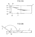
- Figs. 12A and 12B of the accompanying drawings schematically illustrate a known portable telephone set comprising a main body 1 and a swing member 2 linked to each other at an edge 1a of the main body 1 and the corresponding edge 2a of the swing member 2 by means of the paired hinges 3A, 3B of a hinge unit that connect the opposite ends 1b, 1b of the edge 1a to the corresponding knuckle-shaped opposite ends 2b, 2b of the edge 2a respectively.
- the swing member 2 can be folded on the main body 1 as indicated by solid lines in Fig. 12B for the convenience of storage and transportation and then be opened along the phantom lines to an operating position P so that the user can talk to the microphone arranged in the swing member 2 while he or she is holding the main body with a single hand (European Patent Application No. 0 732 474).
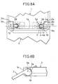
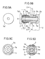
- Figs. 8A through 9C of the accompanying drawings schematically illustrate the paired hinges 3A, 3B of the known hinge unit used in a portable telephone set.
- Fig. 8A is a partial plan view
- Fig. 8B is a partial lateral view of the portable telephone set.
- Each of the hinges 3A, 3B comprises a spring 4 and a camshaft 5 pinched by the spring 4.
- the camshaft 5 is rotatable and unremovably fitted over a cylindrical bearing tube 5a whose base section 5a' is rigidly secured to the main body 1.
- the cam shaft 5 has a protruding section 5b having an enlarged cross section and extending axially and outwardly from the bearing port 1c of the main body 1 in the X-direction that is parallel to the edge 1a of the main body so that it is received by a bearing section 2c formed in the corresponding knuckle-shaped end 2b of the swing member 2.
- the cam shaft also has a cam section 5c.
- the spring 4 fitted over the bearing tube 5a is rigidly secured relative to the edge 1a and has a pair of resilient tips 4a, 4a resiliently abutting the cam section 5c.
- the cam section 5c has a pair of narrowly separated flat surfaces 5d, 5d for providing a stationary state and a pair of outwardly rounded surfaces 5e, 5e for providing an easily rotatable state.
- the telephone set is held either to an operating state or to a resting state by the hinges in a manner as described above.
- the hinges of the known hinge unit require an assembling operation for bringing the protruding section 5b of the main body 1 into engagement with the bearing section 2c of the swing member 2 as shown in Fig. 9B.
- the swing member 2 of the telephone set is made of synthetic resin to make it deformable so that the bearing sections 2c, 2c of the swing member 2 may be brought into engagement with the respective protruding sections 5b, 5b of the main body 1 by forcibly separating the knuckle-shaped opposite ends 2b, 2b from each other.
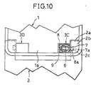
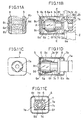
- Figs. 10 through 11E illustrate the hinges 3C, 3D of an improved known hinge unit proposed to eliminate the above identified problem.
- Each of the hinges 3C, 3D of the hinge unit comprises a.spring 6 and a cam shaft 7 pinched by the spring 6.
- the cam shaft 5 is rotatable and unremovable housed in a rectangular sleeve 8 rigidly secured to the main body 1.
- the cam shaft 7 has a protruding section 7a having an enlarged cross section and extending axially and outwardly from the bearing port 8a of the rectangular sleeve 8 in the X-direction that is parallel to the edge 1a of the main body so that it is received by a bearing section 2c formed in the corresponding knuckle-shaped end 2b of the swing member 2.
- Reference symbol 7b in Figs. 11B and 11D denotes an antirelease edge of the cam shaft 7 for preventing the cam shaft 7 from being released from the rectangular sleeve 8 to move away rightward in Figs. 11B and 11D as it abuts the bottom wall of the rectangular sleeve 8 where the bearing port 8a is arranged.
- the cam shaft also has a cam section 5c as seen from Fig. 11E.
- the cam section 7c has a pair of narrowly separated flat surfaces 7d, 7d for providing a standstill state and a pair of outwardly rounded surfaces 7e, 7e for providing an easily rotatable state as in the case of the first known hinge unit.
- the cam section 7c is fitted over a small diameter section 6b of a cylindrical bearing tube 6a of the spring 6 so that the cam shaft 7 is rotatable relative to the small diameter section 6b.
- the remaining large diameter section 6c of the cylindrical bearing tube 6a and the cam section 7c are axially located side by side in the X-direction.
- the large diameter section 6c has low lateral projections 6d, 6d that are engagedly received by respective grooves 8b, 8b formed on the inner wall of the rectangular sleeve 8 such that the cylindrical bearing tube 6a of the spring 6 is axially slidable in the X-direction by a given distance.
- the spring 6 has a spring section 6e rigidly fitted to the small diameter section 6c and a pair of resilient tips 6f, 6f extending from the spring section 6e toward the cam section 7c and adapted to resiliently abut the flat surfaces 7d, 7d for providing a stationary state or the outwardly rounded surfaces 7e, 7e for providing an easily rotatable state of the cam section 7c as in the case of the first known hinge unit.
- a coil spring 9 is arranged between the inner end of the large diameter section 6c of the spring 6 and the end wall members 8c, 8c of the rectangular sleeve 8 arrange opposite to the end where the bearing port 8a is located so that the cam shaft 7 is constantly urged outwardly, or rightward in Figs. 11B and 11D, by the coil spring 9 by way of the spring 6 and hence the antirelease edge 7b of the cam shaft 7 is constantly held in abutment with the corresponding end of the rectangular sleeve 8.
- the second known hinge unit provide a significant advantages over the first known hinge unit.
- each of the hinges of the second known hinge unit still requires the use of not only a pair of resilient tips 6f, 6f for the spring 6 to be held in abutment with the cam section 7c of the cam shaft 7 in order to keep the swing member 2 open relative to the main body 1 by a given angle and also in the closed position but a coil spring 9 in order to allow the protruding section 7a of the cam shaft 7 to restore the original position when it is released after having been pushed into the rectangular sleeve 8.
- the cylindrical bearing tube 6a rigidly holding the resilient tips 6f, 6f is divided into a large diameter section 6c and a small diameter section 6b which has to be fitted into the cam shaft 7 from an end thereof until the large diameter section 6c abuts the cam shaft 7 and the end wall members 8c, 8c of the rectangular sleeve 8 have to be bent after the completion of the assembling operation because they have been left unbent for easy assembling.
- the process of manufacturing and assembling such a hinge device is rather complicated and cumbersome.
- a hinge according to the invention is structurally simple and reliable and allows the operation of assembling the main body and the swing member to be conducted easily and quickly.
- a hinge unit having a pair of hinges for linking a main body and a swing member at the knuckle-shaped respective opposite ends of an edge of the latter to make it swingable relative to the main body around said edge, each of said hinges comprising a spring fitted to the main body or the swing member, and a cam shaft comprising a cam section and a projecting end for engaging either a bearing section of the swing member or the main body, whichever is appropriate, so as to be rotatable along an axis running in parallel with said edge, said spring being resiliently biassed against a tip-holding area of the cam section of the cam shaft at a selected angular position by means of a resilient tip of the spring, characterised in that said cam shaft further comprises a tapered section arranged axially, sequentially and continuously thereof and extending between a small diameter end and a large-diameter end, the cam shaft being axially displaceable relative to the spring by pushing the protruding section of the cam shaft
- the cam section of the cam shaft comprises tip-holding areas for holding the resilient tip and rounded surfaces arranged circumferentially and connected to said tip-holding areas to receive the resilient force of said resilient tip.
- Fig. 1A is a partially cut-away schematic plan view of a first embodiment of hinge unit according to the invention and Fig. 1B is a schematic lateral view of the hinge unit of Fig. 1A.
- the main body 10 is linked to the swing member 11 at the opposite ends 10b, 10b of an edge 10a thereof by way of the respective hinges 12A, 12B of the hinge unit arranged at the knuckle-shaped corresponding opposite ends 11b, 11b of a lateral edge 11a thereof.
- Each of the hinges 12A, 12B comprises a spring and a cam shaft 14 pinched by the spring 13.
- the cam shaft 14 is fitted either to the main body 10 as illustrated or to the swing member 11 to be linked to it and so arranged that it is axially and outwardly movable by a given distance from an unreleaseable end position in the sense of X1 direction or X2 direction of the axis, whichever is appropriate, and rotatable around the axis.
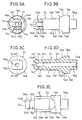
- the cam shaft 14 includes a cam section 14a and a tapered section 14d axially connected to it and extending from a small diameter end 14b to a large diameter end 14c.
- a large -diameter section 14e is extended from the large diameter end 14c of the tapered section 14d.
- the spring 13 is rigidly secured to the inside of an appropriate frame member 10c of the main body 10 or the swing member 11, whichever is appropriate, as shown in Fig. 1A.
- the cam section 14a of the cam shaft 14 has a pair of tip-holding areas adapted to be pinched by a pair of resilient tips 13a, 13a of the spring 13 when the cam shaft 14 is in a particular angular position.
- the tapered section 14d has opposite surface areas extending from the respective tip-holding areas 14f, 14f.
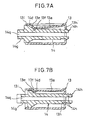
- this second embodiment comprises only one resilient tip 13a adapted to resiliently abut a corresponding tip-holding area 14f to simplify the configuration.
- the cam shaft 14 includes a protruding section 14g axially extending from the tapered section 14d and through a bearing port 10d of the main body 10 (see Figs. 1A and 4) in the sense of X1 direction or X2 direction of the axis, whichever is appropriate, and engagedly received by a bearing section arranged on the swing member 11 or the main body 10, whichever is appropriate so that any rotary force may be transmitted from one to the other.
- the protruding section 14g is realized in the form of a rectangular bar (see Fig. 3C) and the bearing section 11c has a matching rectangular opening.
- the relationship of the cam shaft 14 and the spring 13 is such that, as the protruding section 14g is pushed leftward in Fig. 1C from the normal position indicated by phantom lines, the resilient tips 13a, 13a of the spring 13 is slidingly moved from the cam section 14a of the cam shaft 14 to the small diameter end 14b of the tapered section 14d and then made to ride over the tapered section 14d toward the large diameter end 14c thereof.
- the paired resilient tips 13a, 13a are increasingly separated from each other to accumulate resilient force. If, on the other hand, only a single resilient tip is used, the resilient tip 13a is moved away from the axial line to also accumulate resilient force. As a result, the protruding section 14g can be easily brought into engagement with the bearing section 11c of the swing member 11. When the protruding section 14g is released from the pressure applied to it, the cam shaft 14 is urged to move leftward in Fig1C or rightward in Fig. 7B by the accumulated resilient force of the resilient tip 13a or the resilient tips 13a, 13a, whichever is appropriate, and quickly restore the normal position as shown in Fig. 1D or Fig. 7A, where the swing member 11 is pivotably linked to the main body 10.
- a hinge unit according to the second aspect of the invention has a configuration basically same as that of a hinge unit according to the first aspect of the invention.
- the cam shaft 14 includes an antirelease hook section 14h, a peripherally arranged cam section 14a, a tapered section 14d extending from a small diameter end 14b to a large diameter end 14c and a protruding section 14g to be held in releasable engagement with the bearing section 14c of the swing member 11 of the main body 10, whichever is appropriate, to transmit rotary force, said antirelease hook section 14h, said cam section 14a, said tapered section 14d and said protruding section 14g being arranged sequentially and continuously along the axis of the cam shaft 14.
- the antirelease hook section 14h has a pair of resilient antirelease projections 14i, 14i projecting axially with a void section interposed therebetween and having respective radially standing curved hooks 14k, 14k to respectively define tapered surface areas 14m, 14m and intermediate curved base sections 14n, 14n, which curved base sections 14n, 14n forming a neck 14p as will be described hereinafter.
- reference symbol 14q denotes the axial through hole of the cam shaft 14 through which normally a lead wire is introduced.
- the spring 13 will be described by referring to Figs. 2A and 2B. It comprises a rectangular sleeve 13b rigidly secured to the main body 10 or the swing member 11, whichever is appropriate, by means of said frame member 10c and a pair of U-shaped resilient tips 13a, 13a formed by cutting oppositely disposed axial walls 13c, 13c of the rectangular sleeve 13b and inwardly bending the U-shaped portions so that the front ends 13e, 13c of the resilient tips 13a, 13a are made to approach each other and directed toward the protruding section 14g.
- a single resilient tip 13a may replace the paired resilient tips 13a, 13a.
- the front ends 13e, 13e of the resilient tips 13a, 13a are bent back and directed to the respective walls 13c, 13c to produce curved sliding surface areas 13f, 13f adapted to slide smoothly on the cam section 14a and the respective surface areas of the tapered section 14d.
- the rectangular sleeve 13b is additionally provided at the inner end wall 13g thereof with an opening 13h and at the opposite end with a bearing port 13i.
- the cam shaft 14 is moved into the rectangular sleeve 13b through the bearing port 13i with the antirelease hook section 14h leading the movement and the tapered surface areas 14m, 14m of the resilient antirelease projections 14i, 14i of the antirelease hook section 14h pass through the front opening 13h of the rectangular sleeve 13b, the resilient antirelease projections 14i, 14i are inwardly bent by the peripheral edge of the front opening 13h and the neck 14p becomes engaged with the peripheral edge of the front opening 13h as seen from Figs. 1C, 1D and 4.
- the large diameter section 14e extending from the tapered section 14d is received by the bearing port 13i of the rectangular sleeve 13b.
- the swing member 11 can be linked to the main body 10, or vice versa, easily and quickly simply by axially moving the cam shaft 14.
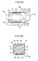
- the cam shaft 14 can be resiliently held by the resilient tip 13a or tips 13a, 13a of the spring 13 at the tip-holding area 14f or areas 14f, 14f, whichever is appropriate, of the cam section 14a as shown in Fig. 5A. Still additionally, the cam shaft 14 is also provided with rounded surfaces 14r, 14r that are circumferentially connected to the tip-holding areas 14f, 14f and subjected to the resilient force of the resilient tips 13a, 13a as shown in Figs. 6A and 6B.
- the swing member 11 is held to a closed position relative to the main body 10.
- the resilient tips 13a, 13a pinch the cam shaft 14 at the tip-holding areas 14f, 14f to keep the swing member 11 to the open position.
- the swing member can be held to an open position relative to the main body where the swing member shows a given angle relative to the main body as in the case of known hinge units and the swing member can be linked to the main body easily and quickly during the assembling operation.
- a hinge unit according to the invention does not require a coil spring as in the case of the above described known hinge unit where the cam shaft pushed into a spring has to be moved back by means of the resilient force of a coil spring in order to restore the rotatable position of the cam shaft
- a hinge unit according to the first aspect of the invention is provided with a tapered section so that a single spring can operates also as the coil spring to simplify the overall configuration of the hinge unit and make the hinge unit compact, light-weight and hence less costly, although the main body and the swing member can be linked together with an enhanced degree of easiness and quickness.
- the cam shaft additionally comprises an antirelease hook section and the resilient tips are formed by cutting the spring and made to slidingly abut the tip-holding areas or the rounded surfaces of the cam section of the cam shaft to provide the binge unit with an increased reliability of operation as compared with a hinge unit according to the first aspect of the invention.
Landscapes
- Engineering & Computer Science (AREA)
- Signal Processing (AREA)
- Mechanical Engineering (AREA)
- Pivots And Pivotal Connections (AREA)
- Telephone Set Structure (AREA)
- Hinge Accessories (AREA)
Description
- This invention relates to a hinge unit and more particularly but not solely a hinge unit for a portable electronic apparatus such as a portable telephone set, a portable computer or an electronic note book that comprises a body and a swing member typically containing a microphone and secured to the main body by means of hinges such that the swing member may be folded on the main body for the convenience of storage when not in use and opened from the main body by a desired angle and held to the open position for use.
- Figs. 12A and 12B of the accompanying drawings schematically illustrate a known portable telephone set comprising a
main body 1 and aswing member 2 linked to each other at anedge 1a of themain body 1 and thecorresponding edge 2a of theswing member 2 by means of thepaired hinges opposite ends edge 1a to the corresponding knuckle-shapedopposite ends edge 2a respectively. - With this arrangement, the
swing member 2 can be folded on themain body 1 as indicated by solid lines in Fig. 12B for the convenience of storage and transportation and then be opened along the phantom lines to an operating position P so that the user can talk to the microphone arranged in theswing member 2 while he or she is holding the main body with a single hand (European Patent Application No. 0 732 474). - Figs. 8A through 9C of the accompanying drawings schematically illustrate the paired
hinges - Each of the
hinges spring 4 and acamshaft 5 pinched by thespring 4. As seen from Figs. 9A and 9B, thecamshaft 5 is rotatable and unremovably fitted over acylindrical bearing tube 5a whosebase section 5a' is rigidly secured to themain body 1. Thecam shaft 5 has aprotruding section 5b having an enlarged cross section and extending axially and outwardly from thebearing port 1c of themain body 1 in the X-direction that is parallel to theedge 1a of the main body so that it is received by abearing section 2c formed in the corresponding knuckle-shaped end 2b of theswing member 2. - The cam shaft also has a
cam section 5c. Thespring 4 fitted over thebearing tube 5a is rigidly secured relative to theedge 1a and has a pair ofresilient tips cam section 5c. As seen from Figs. 9A through 9D, thecam section 5c has a pair of narrowly separatedflat surfaces rounded surfaces - Thus, with the paired
hinges swing member 2 is turned from the closed position in Fig. 12B to the open position indicated by phantom lines, thecam section 5c of thecam shaft 5 of each of the hinges turns relative to thespring 4 and theflat surfaces resilient tip swing member 4 in the open position, or operating position P, so that the user can operates the telephone set. When theswing member 2 is turned back to the closed position indicated by solid lines, theresilient tips rounded surfaces cam section 5c to hold theswing member 2 to the open position. - Therefore, the telephone set is held either to an operating state or to a resting state by the hinges in a manner as described above. However, the hinges of the known hinge unit require an assembling operation for bringing the protruding
section 5b of themain body 1 into engagement with thebearing section 2c of theswing member 2 as shown in Fig. 9B. More specifically, theswing member 2 of the telephone set is made of synthetic resin to make it deformable so that thebearing sections swing member 2 may be brought into engagement with the respective protrudingsections main body 1 by forcibly separating the knuckle-shapedopposite ends - Thus, considerable force have to be applied to the swing member to assemble the known portable telephone set. Such an assembling operation is time consuming and requires a considerable work load.
- Figs. 10 through 11E illustrate the
hinges - While the known hinges have a configuration basically same as that of the hinges of Figs. 8A through 9D, they provide an improvement as discussed below.
- Each of the
hinges spring 6 and acam shaft 7 pinched by thespring 6. As seen from Figs. 11A through 11E, thecam shaft 5 is rotatable and unremovable housed in arectangular sleeve 8 rigidly secured to themain body 1. Additionally, thecam shaft 7 has aprotruding section 7a having an enlarged cross section and extending axially and outwardly from thebearing port 8a of therectangular sleeve 8 in the X-direction that is parallel to theedge 1a of the main body so that it is received by abearing section 2c formed in the corresponding knuckle-shaped end 2b of theswing member 2. - Reference symbol 7b in Figs. 11B and 11D denotes an antirelease edge of the
cam shaft 7 for preventing thecam shaft 7 from being released from therectangular sleeve 8 to move away rightward in Figs. 11B and 11D as it abuts the bottom wall of therectangular sleeve 8 where thebearing port 8a is arranged. - The cam shaft also has a
cam section 5c as seen from Fig. 11E. Thecam section 7c has a pair of narrowly separatedflat surfaces rounded surfaces - The
cam section 7c is fitted over asmall diameter section 6b of a cylindrical bearing tube 6a of thespring 6 so that thecam shaft 7 is rotatable relative to thesmall diameter section 6b. Thus, the remaininglarge diameter section 6c of the cylindrical bearing tube 6a and thecam section 7c are axially located side by side in the X-direction. Additionally, as seen from Figs. 11A and 11B, thelarge diameter section 6c has lowlateral projections respective grooves rectangular sleeve 8 such that the cylindrical bearing tube 6a of thespring 6 is axially slidable in the X-direction by a given distance. - Still additionally, the
spring 6 has aspring section 6e rigidly fitted to thesmall diameter section 6c and a pair ofresilient tips spring section 6e toward thecam section 7c and adapted to resiliently abut theflat surfaces rounded surfaces cam section 7c as in the case of the first known hinge unit. - A
coil spring 9 is arranged between the inner end of thelarge diameter section 6c of thespring 6 and theend wall members rectangular sleeve 8 arrange opposite to the end where thebearing port 8a is located so that thecam shaft 7 is constantly urged outwardly, or rightward in Figs. 11B and 11D, by thecoil spring 9 by way of thespring 6 and hence the antirelease edge 7b of thecam shaft 7 is constantly held in abutment with the corresponding end of therectangular sleeve 8. - With this arrangement, when the protruding
section 7a protruding from thebearing port 1c of themain body 1 to an extreme position as indicated by phantom lines in Fig. 11D is pushed back, or leftward in Fig. 11D, by applying pressure thereto, the applied pressure is transmitted to thecoil spring 9 by way of thecam shaft 7 and the cylindrical bearing tube 6a to force the cylindrical bearing tube to move in the X-direction as it is guided by thegrooves rectangular sleeve 8 until the protrudingsection 7 is moved to the opposite extreme position indicated by solid lines, when thecoil spring 9 is completely compressed. - Thus, if the extent to which the coil spring is compressed is properly selected, the operation of bringing the protruding
section 7a of thecam shaft 7 into engagement with thebearing section 2c of theswing member 2 can be performed quickly and easily simply by pushing back the protrudingsection 7a by means of a finger tip and then quickly pushing the corresponding knuckle-shaped end 2b of theswing member 2 toward the main body. Therefore, the second known hinge unit provide a significant advantages over the first known hinge unit. - However, each of the hinges of the second known hinge unit still requires the use of not only a pair of
resilient tips spring 6 to be held in abutment with thecam section 7c of thecam shaft 7 in order to keep theswing member 2 open relative to themain body 1 by a given angle and also in the closed position but acoil spring 9 in order to allow the protrudingsection 7a of thecam shaft 7 to restore the original position when it is released after having been pushed into therectangular sleeve 8. - Additionally, the cylindrical bearing tube 6a rigidly holding the
resilient tips large diameter section 6c and asmall diameter section 6b which has to be fitted into thecam shaft 7 from an end thereof until thelarge diameter section 6c abuts thecam shaft 7 and theend wall members rectangular sleeve 8 have to be bent after the completion of the assembling operation because they have been left unbent for easy assembling. Thus, the process of manufacturing and assembling such a hinge device is rather complicated and cumbersome. - In view of the above identified problems of the second known hinge unit, it is therefore an object of the present invention to provide an improved hinge wherein, as the cam shaft is pushed into the rectangular sleeve, the spring that has been held in abutment with the cam section of the camshaft to press the latter is made to ride over a tapered section connected to the cam shaft and move toward the large-diameter end thereof.
- If the pressure applied to the cam shaft is released under this condition, the cam section is slidingly moved back from the tapered section to the cam section by way of the small diameter end of the tapered section only by the resilient force of the spring so that the cam shaft may restore the original position and the swing member may be operated and held to either a stationary state or an easily rotatable state by the rotary motion of the cam shaft without requiring the use of a coil spring unlike the case of the second known hinge unit. Thus, a hinge according to the invention is structurally simple and reliable and allows the operation of assembling the main body and the swing member to be conducted easily and quickly.
- Thus, in accordance with this invention there is provided a hinge unit having a pair of hinges for linking a main body and a swing member at the knuckle-shaped respective opposite ends of an edge of the latter to make it swingable relative to the main body around said edge, each of said hinges comprising a spring fitted to the main body or the swing member, and a cam shaft comprising a cam section and a projecting end for engaging either a bearing section of the swing member or the main body, whichever is appropriate, so as to be rotatable along an axis running in parallel with said edge, said spring being resiliently biassed against a tip-holding area of the cam section of the cam shaft at a selected angular position by means of a resilient tip of the spring, characterised in that said cam shaft further comprises a tapered section arranged axially, sequentially and continuously thereof and extending between a small diameter end and a large-diameter end, the cam shaft being axially displaceable relative to the spring by pushing the protruding section of the cam shaft inwardly by a given distance from an unreleasable position to a releasable position to cause said resilient tip of the spring to slidingly move toward the large-diameter end of the tapered section, the resilient force of said resilient tip on the tapered section said cam shaft acting to push the cam shaft outwardly to restore said unreleasable position.
- Preferably the cam section of the cam shaft comprises tip-holding areas for holding the resilient tip and rounded surfaces arranged circumferentially and connected to said tip-holding areas to receive the resilient force of said resilient tip.
-
- Fig. 1A is a partially cut-away schematic plan view of an embodiment of hinge unit according to the invention.
- Fig. 1B is a schematic lateral view of the hinge unit of Fig. 1A.
- Fig. 1C is a schematic cross sectional plan view of one of the hinges of the hinge unit of Fig. 1A, where the cam shaft is forcibly pushed into the sleeve.
- Fig. 1D is a schematic cross sectional plan view of one of the hinges of the hinge unit similar to Fig. 1C but showing the cam shaft restored to the normal position.
- Fig. 2A is a schematic cross sectional plan view of the spring of the hinge of Fig. 1C.
- Fig. 2B is a schematic plan view of the spring of Fig. 2A.
- Fig. 3A is a schematic lateral view of the cam shaft of the hinge of Fig. 1C.
- Fig. 3B is a schematic plan view of the cam shift of Fig. 3A.
- Fig. 3C is a schematic lateral view of the cam shaft of Fig. 3A as viewed from the opposite side.
- Fig. 3D is a schematic cross sectional view of the cam shaft taken along line D-D in Fig. 3C.
- Fig. 3E is a schematic plan view of the cam shaft of Fig. 3A placed at a different angular position.
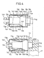
- Fig. 4 is a schematic cross sectional plan view of the hinge of Fig. 1C, showing how the main body and the swing member are linked.
- Fig. 5A is a schematic cross sectional plan view of the hinge of Fig. 1C in a state where the swing member is opened.
- Fig. 5B is a schematic cross sectional view of the hinge of Fig. 5A taking along line B-B in Fig. 5A.
- Fig. 6A is a schematic cross sectional plan view of the hinge of Fig. 1C in a state where the swing member is closed.
- Fig. 6B is a schematic cross sectional view of the hinge of Fig. 6A taking along line B-B in Fig. 6A.
- Fig. 7A is a schematic cross sectional plan view of one of the hinges of another embodiment of hinge unit according to the invention.
- Fig. 7B is a schematic cross sectional view similar to Fig. 7A but showing the cam shaft pushed into the sleeve.
- Fig. 8A is a partially cut-away schematic plan view of a known hinge unit.
- Fig. 8B is a schematic lateral view of the hinge unit of Fig. 8A.
- Fig. 9A is a schematic front view of one of the hinges of the hinge unit of Fig. 8A.
- Fig. 9B is a schematic cross sectional plan view of the hinge of Fig. 9A, illustrating how the main body and the swing member are linked.
- Fig. 9C is a schematic rear view of the hinge of Fig. 9A.
- Fig. 9D is a schematic cross sectional view of the hinge of Fig. 9B taken along line D-D in Fig. 9B.
- Fig. 10 is a partly cut-away schematic plan view of another known hinge unit obtained improving that of Fig. 8A.
- Fig. 11A is a schematic front view of one of the hinges of the hinge unit of Fig. 10.
- Fig. 11B is a schematic cross sectional plan view of the hinge of Fig. 11A, illustrating how the main body and the swing member are linked.
- Fig. 11C is a schematic rear view of the hinge of Fig. 11A.
- Fig. 11D is a schematic cross sectional view of the hinge of Fig. 11B taken along line D-D in Fig. 11B.
- Fig. 12A is a schematic plan view of a portable telephone set using a known hinge unit.
- Fig. 12B is a schematic lateral view of the portable telephone set of Fig. 12A.
-
- Now, the present invention will be described by referring to the accompanying illustrating preferred embodiments thereof applied to a portable telephone set. Fig. 1A is a partially cut-away schematic plan view of a first embodiment of hinge unit according to the invention and Fig. 1B is a schematic lateral view of the hinge unit of Fig. 1A. Referring to Figs. 1A and 1B, the
main body 10 is linked to theswing member 11 at the opposite ends 10b, 10b of anedge 10a thereof by way of the respective hinges 12A, 12B of the hinge unit arranged at the knuckle-shaped corresponding opposite ends 11b, 11b of alateral edge 11a thereof. Each of thehinges cam shaft 14 pinched by thespring 13. - The
cam shaft 14 is fitted either to themain body 10 as illustrated or to theswing member 11 to be linked to it and so arranged that it is axially and outwardly movable by a given distance from an unreleaseable end position in the sense of X1 direction or X2 direction of the axis, whichever is appropriate, and rotatable around the axis. - As seen from Figs. 1C and 1D, the
cam shaft 14 includes acam section 14a and atapered section 14d axially connected to it and extending from asmall diameter end 14b to alarge diameter end 14c. In the case of the illustrated embodiment, a large -diameter section 14e is extended from thelarge diameter end 14c of the taperedsection 14d. - On the other hand, the
spring 13 is rigidly secured to the inside of an appropriate frame member 10c of themain body 10 or theswing member 11, whichever is appropriate, as shown in Fig. 1A. - In the illustrated embodiment, the
cam section 14a of thecam shaft 14 has a pair of tip-holding areas adapted to be pinched by a pair ofresilient tips spring 13 when thecam shaft 14 is in a particular angular position. Note that the taperedsection 14d has opposite surface areas extending from the respective tip-holdingareas - It will be appreciated by referring to Fig. 7 showing another embodiment of the invention that this second embodiment comprises only one
resilient tip 13a adapted to resiliently abut a corresponding tip-holdingarea 14f to simplify the configuration. - The
cam shaft 14 includes a protrudingsection 14g axially extending from the taperedsection 14d and through abearing port 10d of the main body 10 (see Figs. 1A and 4) in the sense of X1 direction or X2 direction of the axis, whichever is appropriate, and engagedly received by a bearing section arranged on theswing member 11 or themain body 10, whichever is appropriate so that any rotary force may be transmitted from one to the other. In the illustrated embodiment, the protrudingsection 14g is realized in the form of a rectangular bar (see Fig. 3C) and thebearing section 11c has a matching rectangular opening. - The relationship of the
cam shaft 14 and thespring 13 is such that, as the protrudingsection 14g is pushed leftward in Fig. 1C from the normal position indicated by phantom lines, theresilient tips spring 13 is slidingly moved from thecam section 14a of thecam shaft 14 to thesmall diameter end 14b of the taperedsection 14d and then made to ride over the taperedsection 14d toward thelarge diameter end 14c thereof. - Thus, if a pair of resilient tips are used, the paired
resilient tips resilient tip 13a is moved away from the axial line to also accumulate resilient force. As a result, the protrudingsection 14g can be easily brought into engagement with thebearing section 11c of theswing member 11. When the protrudingsection 14g is released from the pressure applied to it, thecam shaft 14 is urged to move leftward in Fig1C or rightward in Fig. 7B by the accumulated resilient force of theresilient tip 13a or theresilient tips swing member 11 is pivotably linked to themain body 10. - A hinge unit according to the second aspect of the invention has a configuration basically same as that of a hinge unit according to the first aspect of the invention. However, as shown in Fig. 3B, the
cam shaft 14 includes anantirelease hook section 14h, a peripherally arrangedcam section 14a, atapered section 14d extending from asmall diameter end 14b to alarge diameter end 14c and a protrudingsection 14g to be held in releasable engagement with thebearing section 14c of theswing member 11 of themain body 10, whichever is appropriate, to transmit rotary force, saidantirelease hook section 14h, saidcam section 14a, saidtapered section 14d and said protrudingsection 14g being arranged sequentially and continuously along the axis of thecam shaft 14. - As shown in Figs. 3A and 3B, the
antirelease hook section 14h has a pair ofresilient antirelease projections curved hooks surface areas curved base sections base sections neck 14p as will be described hereinafter. Referring to Figs. 3A, 3C and 3D, reference symbol 14q denotes the axial through hole of thecam shaft 14 through which normally a lead wire is introduced. - Now, the
spring 13 will be described by referring to Figs. 2A and 2B. It comprises arectangular sleeve 13b rigidly secured to themain body 10 or theswing member 11, whichever is appropriate, by means of said frame member 10c and a pair of U-shapedresilient tips axial walls rectangular sleeve 13b and inwardly bending the U-shaped portions so that thefront ends resilient tips section 14g. However, as described earlier by referring to Figs. 7A and 7B, a singleresilient tip 13a may replace the pairedresilient tips - Referring back to Figs. 2A and 2B, the
front ends resilient tips respective walls surface areas cam section 14a and the respective surface areas of the taperedsection 14d. - The
rectangular sleeve 13b is additionally provided at theinner end wall 13g thereof with anopening 13h and at the opposite end with abearing port 13i. Thus, as thecam shaft 14 is moved into therectangular sleeve 13b through the bearingport 13i with theantirelease hook section 14h leading the movement and the taperedsurface areas resilient antirelease projections antirelease hook section 14h pass through thefront opening 13h of therectangular sleeve 13b, theresilient antirelease projections front opening 13h and theneck 14p becomes engaged with the peripheral edge of thefront opening 13h as seen from Figs. 1C, 1D and 4. - Then, as shown in Fig. 4, the radially standing
curved hooks inner end wall 13g to make the cam shaft rightward unreleaseable in Fig. 4. Note that the curved slidingsurface areas resilient tips cam section 14a under this condition. - In the above unreleaseable condition, the
large diameter section 14e extending from the taperedsection 14d is received by the bearingport 13i of therectangular sleeve 13b. - Thus, as the protruding
section 14g of thecam shaft 14 is pushed into the rectangular sleeve further as descnbed above, theresilient tips rectangular sleeve 13 are slidingly moved from thecam section 13a toward thelarge diameter end 14c of the taperedsection 14d by way of thesmall diameter end 14b. Once the pressure for inwardly urging the protrudingsection 14g is released, thecam shaft 14 is pushed back by the resilient force of theresilient tips curved hooks antirelease hook section 14h come into engagement with the peripheral edge of theopening 13h of thefront end wall 13g. This provides an improvement relative to the arrangement according to the first aspect of the invention as described earlier. - According to the second aspect of the invention, the
swing member 11 can be linked to themain body 10, or vice versa, easily and quickly simply by axially moving thecam shaft 14. - Additionally, the
cam shaft 14 can be resiliently held by theresilient tip 13a ortips spring 13 at the tip-holdingarea 14f orareas cam section 14a as shown in Fig. 5A. Still additionally, thecam shaft 14 is also provided withrounded surfaces areas resilient tips - Thus, when the
resilient tips rounded surfaces swing member 11 is held to a closed position relative to themain body 10. When, on the other hand, theswing member 11 is opened by a given angle relative to themain body 10, theresilient tips cam shaft 14 at the tip-holdingareas swing member 11 to the open position. - As described above in detail, with a hinge unit according to the first aspect of the invention, the swing member can be held to an open position relative to the main body where the swing member shows a given angle relative to the main body as in the case of known hinge units and the swing member can be linked to the main body easily and quickly during the assembling operation. What is remarkable with a hinge unit according to the invention lies in that it does not require a coil spring as in the case of the above described known hinge unit where the cam shaft pushed into a spring has to be moved back by means of the resilient force of a coil spring in order to restore the rotatable position of the cam shaft Instead, a hinge unit according to the first aspect of the invention is provided with a tapered section so that a single spring can operates also as the coil spring to simplify the overall configuration of the hinge unit and make the hinge unit compact, light-weight and hence less costly, although the main body and the swing member can be linked together with an enhanced degree of easiness and quickness.
- In a hinge unit according to the invention, the cam shaft additionally comprises an antirelease hook section and the resilient tips are formed by cutting the spring and made to slidingly abut the tip-holding areas or the rounded surfaces of the cam section of the cam shaft to provide the binge unit with an increased reliability of operation as compared with a hinge unit according to the first aspect of the invention.
Claims (2)
- A hinge unit having a pair of hinges (12a, 12b) for linking a main body (10) and a swing member (11) at the knuckle-shaped respective opposite ends (10b, 10b) of an edge (10a) of the latter to make it swingable relative to the main body (10) around said edge (10a), each of said hinges (12a, 12b) comprising a spring (13) fitted to the main body (10) or the swing member (11), and a cam shaft (14) comprising a cam section (14a) and a projecting end (14g) for engaging either a bearing section (11c) of the swing member (11) or the main body (10), whichever is appropriate, so as to be rotatable along an axis running in parallel with said edge (10a), said spring (13) being resiliently biassed against a tip-holding area (14f) of the cam section (14a) of the cam shaft (14) at a selected angular position by means of a resilient tip (13a) of the spring (13), characterised in that said cam shaft (14) further comprises a tapered section (14d) arranged axially, sequentially and continuously thereof and extending between a small diameter end (14b) and a large-diameter end (14c), the cam shaft (14) being axially displaceable relative to the spring (13) by pushing the protruding section (14g) of the cam shaft (14) inwardly by a given distance from an unreleasable position to a releasable position to cause said resilient tip (13a) of the spring (13) to slidingly move toward the large-diameter end (14c) of the tapered section (14d), the resilient force of said resilient tip (13a) on the tapered section (14d) of said cam shaft (14) acting to push the cam shaft (14) outwardly to restore said unreleasable position.
- A hinge unit as claimed in claim 1, characterised in that said cam section (14a) of the cam shaft (14) comprises tip-holding areas (14f) for holding the resilient tip (13a) and rounded surfaces (14r) arranged circumferentially and connected to said tip-holding areas (14f) to receive the resilient force of said resilient tip (13a).
Applications Claiming Priority (2)
| Application Number | Priority Date | Filing Date | Title |
|---|---|---|---|
| JP4283098 | 1998-02-09 | ||
| JP10042830A JP2906346B1 (en) | 1998-02-09 | 1998-02-09 | Hinge device |
Publications (3)
| Publication Number | Publication Date |
|---|---|
| EP0935376A2 EP0935376A2 (en) | 1999-08-11 |
| EP0935376A3 EP0935376A3 (en) | 2002-04-03 |
| EP0935376B1 true EP0935376B1 (en) | 2005-10-12 |
Family
ID=12646894
Family Applications (1)
| Application Number | Title | Priority Date | Filing Date |
|---|---|---|---|
| EP99300827A Expired - Lifetime EP0935376B1 (en) | 1998-02-09 | 1999-02-04 | Hinge unit for a portable electronic device |
Country Status (6)
| Country | Link |
|---|---|
| US (1) | US6119310A (en) |
| EP (1) | EP0935376B1 (en) |
| JP (1) | JP2906346B1 (en) |
| KR (1) | KR100259221B1 (en) |
| CN (1) | CN1116530C (en) |
| DE (1) | DE69927628T2 (en) |
Families Citing this family (26)
| Publication number | Priority date | Publication date | Assignee | Title |
|---|---|---|---|---|
| JP3658250B2 (en) | 1999-08-06 | 2005-06-08 | スガツネ工業株式会社 | Hinge |
| GB2352769B (en) * | 1999-08-06 | 2001-06-20 | Sugatsune Kogyo | Hinge assembly |
| EP1205035A1 (en) * | 1999-08-12 | 2002-05-15 | Ki-Young Kim | Apparatus and method for opening a cover of a mobile phone |
| TW547684U (en) * | 1999-10-26 | 2003-08-11 | Hon Hai Prec Ind Co Ltd | Pivot structure |
| JP3517384B2 (en) * | 2000-04-04 | 2004-04-12 | スガツネ工業株式会社 | Hinge device |
| USD480717S1 (en) | 2000-11-09 | 2003-10-14 | Sugatsune Kogyo Co., Ltd. | Hinge for cellular telephone |
| JP3930685B2 (en) * | 2001-01-29 | 2007-06-13 | 加藤電機株式会社 | Snap fit hinge |
| US6539580B2 (en) * | 2001-04-20 | 2003-04-01 | Hewlett-Packard Company | Hinge assembly for a cover |
| US6871384B2 (en) * | 2001-05-11 | 2005-03-29 | Cema Technologies, Inc. | Hinge assembly for rotatably mounting a display to a surface |
| KR100446492B1 (en) * | 2001-07-05 | 2004-09-01 | 삼성전자주식회사 | Hinge device for storage case, and storage case having the same |
| JP4153714B2 (en) * | 2002-04-08 | 2008-09-24 | Hoya株式会社 | Hinge structure |
| TW575067U (en) * | 2003-06-06 | 2004-02-01 | Hon Hai Prec Ind Co Ltd | Hinge mechanism |
| KR100560682B1 (en) | 2003-06-19 | 2006-03-16 | 삼성전자주식회사 | Storage |
| TWI246390B (en) * | 2003-07-10 | 2005-12-21 | Benq Corp | Axle positioning structure |
| CN101126411B (en) * | 2004-02-04 | 2010-06-02 | Phoenixkorea株式会社 | Portable electronic device |
| US20060168758A1 (en) * | 2005-01-28 | 2006-08-03 | Teng-Chao Chiang | Hinge structure |
| TWI292520B (en) * | 2005-06-29 | 2008-01-11 | Asustek Comp Inc | Portable electronic device capable of reversing a screen |
| WO2007114584A1 (en) * | 2006-04-04 | 2007-10-11 | Laird Technologies Map Co., Ltd. | Slide-up opening and closing mechanism for portable terminal |
| KR100874633B1 (en) * | 2008-04-01 | 2008-12-17 | 주식회사 아이원이노텍 | Detachable automatic return hinge |
| CN102200167A (en) * | 2010-03-24 | 2011-09-28 | 鸿富锦精密工业(深圳)有限公司 | Hinge structure |
| KR101352478B1 (en) | 2013-01-18 | 2014-01-21 | 동원산업 주식회사 | Main shaft conclusion structure of the gearshift lever for cars |
| US10732677B2 (en) * | 2017-04-26 | 2020-08-04 | Intel Corporation | Close clearance hinge systems |
| US10228732B2 (en) | 2017-05-19 | 2019-03-12 | Microsoft Technology Licensing, Llc | Hinge with variable sliding friction |
| US10545540B2 (en) | 2017-07-06 | 2020-01-28 | Microsoft Technology Licensing, Llc | Systems and methods of longitudinal torsional resistance in a hinge |
| US11564538B2 (en) | 2019-10-21 | 2023-01-31 | Bemis Manufacturing Company | Hinge post for toilet seat |
| CN111623031B (en) * | 2019-12-11 | 2021-08-27 | 北京计算机技术及应用研究所 | Turnover screen fixing device |
Family Cites Families (5)
| Publication number | Priority date | Publication date | Assignee | Title |
|---|---|---|---|---|
| US2622922A (en) * | 1950-02-27 | 1952-12-23 | Charles D Schroeder | Glare shield |
| JPH057629Y2 (en) * | 1986-08-29 | 1993-02-25 | ||
| JP3007552B2 (en) * | 1994-08-30 | 2000-02-07 | 株式会社加藤スプリング製作所 | Hinge device |
| US5715575A (en) * | 1995-03-13 | 1998-02-10 | Kato Spring Works Co., Ltd. | Hinge device |
| GB2322906B (en) * | 1996-12-23 | 2001-04-04 | Nokia Mobile Phones Ltd | Spring biased hinge for a foldable radiotelephone |
-
1998
- 1998-02-09 JP JP10042830A patent/JP2906346B1/en not_active Expired - Fee Related
- 1998-03-11 KR KR1019980007981A patent/KR100259221B1/en not_active Expired - Fee Related
- 1998-09-08 US US09/148,901 patent/US6119310A/en not_active Expired - Fee Related
-
1999
- 1999-02-04 DE DE69927628T patent/DE69927628T2/en not_active Expired - Fee Related
- 1999-02-04 EP EP99300827A patent/EP0935376B1/en not_active Expired - Lifetime
- 1999-02-09 CN CN99102198A patent/CN1116530C/en not_active Expired - Fee Related
Also Published As
| Publication number | Publication date |
|---|---|
| CN1225983A (en) | 1999-08-18 |
| DE69927628T2 (en) | 2006-07-20 |
| EP0935376A2 (en) | 1999-08-11 |
| HK1020369A1 (en) | 2000-04-14 |
| DE69927628D1 (en) | 2005-11-17 |
| EP0935376A3 (en) | 2002-04-03 |
| US6119310A (en) | 2000-09-19 |
| CN1116530C (en) | 2003-07-30 |
| KR100259221B1 (en) | 2000-06-15 |
| KR19990071332A (en) | 1999-09-27 |
| JPH11230155A (en) | 1999-08-27 |
| JP2906346B1 (en) | 1999-06-21 |
Similar Documents
| Publication | Publication Date | Title |
|---|---|---|
| US6119310A (en) | Hinge unit | |
| US7100244B2 (en) | Hinge assembly and portable electronic device having same | |
| US5938229A (en) | One-handed foldable stroller | |
| US6148480A (en) | Hinge construction with a snap-open, snap-shut feel, for a folding mobile phone handset | |
| US5557587A (en) | Connecting structure for a wrist watch | |
| EP1167786A1 (en) | Hinge | |
| EP1843052A1 (en) | Hinge device | |
| US20040237259A1 (en) | Hinge assembly | |
| US20040131421A1 (en) | Opening and closing device | |
| US6405411B1 (en) | Catch at a pressring | |
| US20010002544A1 (en) | Flat key | |
| US20020073557A1 (en) | Expandable tubular body | |
| US6282796B1 (en) | Hole-punching pliers | |
| JP2002502575A (en) | Quick connect antenna | |
| US20030234509A1 (en) | Bicycle folding device | |
| JP2020065572A (en) | Connector for accessories | |
| EP1843053A1 (en) | Folding electronic apparatus | |
| JP3145663B2 (en) | Hinge device | |
| CN1997830A (en) | Two-axis hinge device | |
| JP4353195B2 (en) | Sliding door structure | |
| KR100276174B1 (en) | Hinge device | |
| KR960004276Y1 (en) | Key holder | |
| JPH06191498A (en) | Flexing mechanism for expanded structural materials | |
| JPH07289342A (en) | Operation mechanism of eyelash curler | |
| JP4447739B2 (en) | Mop holder |
Legal Events
| Date | Code | Title | Description |
|---|---|---|---|
| PUAI | Public reference made under article 153(3) epc to a published international application that has entered the european phase |
Free format text: ORIGINAL CODE: 0009012 |
|
| AK | Designated contracting states |
Kind code of ref document: A2 Designated state(s): AT BE CH CY DE DK ES FI FR GB GR IE IT LI LU MC NL PT SE Kind code of ref document: A2 Designated state(s): DE FR GB IT |
|
| AX | Request for extension of the european patent |
Free format text: AL;LT;LV;MK;RO;SI |
|
| PUAL | Search report despatched |
Free format text: ORIGINAL CODE: 0009013 |
|
| AK | Designated contracting states |
Kind code of ref document: A3 Designated state(s): AT BE CH CY DE DK ES FI FR GB GR IE IT LI LU MC NL PT SE |
|
| AX | Request for extension of the european patent |
Free format text: AL;LT;LV;MK;RO;SI |
|
| 17P | Request for examination filed |
Effective date: 20021002 |
|
| AKX | Designation fees paid |
Free format text: DE FR GB IT |
|
| 17Q | First examination report despatched |
Effective date: 20030124 |
|
| GRAP | Despatch of communication of intention to grant a patent |
Free format text: ORIGINAL CODE: EPIDOSNIGR1 |
|
| GRAS | Grant fee paid |
Free format text: ORIGINAL CODE: EPIDOSNIGR3 |
|
| GRAA | (expected) grant |
Free format text: ORIGINAL CODE: 0009210 |
|
| AK | Designated contracting states |
Kind code of ref document: B1 Designated state(s): DE FR GB IT |
|
| REG | Reference to a national code |
Ref country code: GB Ref legal event code: FG4D |
|
| REF | Corresponds to: |
Ref document number: 69927628 Country of ref document: DE Date of ref document: 20051117 Kind code of ref document: P |
|
| ET | Fr: translation filed | ||
| PLBE | No opposition filed within time limit |
Free format text: ORIGINAL CODE: 0009261 |
|
| STAA | Information on the status of an ep patent application or granted ep patent |
Free format text: STATUS: NO OPPOSITION FILED WITHIN TIME LIMIT |
|
| 26N | No opposition filed |
Effective date: 20060713 |
|
| PGFP | Annual fee paid to national office [announced via postgrant information from national office to epo] |
Ref country code: GB Payment date: 20070131 Year of fee payment: 9 |
|
| PGFP | Annual fee paid to national office [announced via postgrant information from national office to epo] |
Ref country code: DE Payment date: 20070201 Year of fee payment: 9 |
|
| PGFP | Annual fee paid to national office [announced via postgrant information from national office to epo] |
Ref country code: IT Payment date: 20070528 Year of fee payment: 9 |
|
| PGFP | Annual fee paid to national office [announced via postgrant information from national office to epo] |
Ref country code: FR Payment date: 20070208 Year of fee payment: 9 |
|
| GBPC | Gb: european patent ceased through non-payment of renewal fee |
Effective date: 20080204 |
|
| PG25 | Lapsed in a contracting state [announced via postgrant information from national office to epo] |
Ref country code: DE Free format text: LAPSE BECAUSE OF NON-PAYMENT OF DUE FEES Effective date: 20080902 |
|
| PG25 | Lapsed in a contracting state [announced via postgrant information from national office to epo] |
Ref country code: GB Free format text: LAPSE BECAUSE OF NON-PAYMENT OF DUE FEES Effective date: 20080204 |
|
| PG25 | Lapsed in a contracting state [announced via postgrant information from national office to epo] |
Ref country code: IT Free format text: LAPSE BECAUSE OF NON-PAYMENT OF DUE FEES Effective date: 20080204 |
|
| REG | Reference to a national code |
Ref country code: FR Ref legal event code: ST Effective date: 20111209 |
|
| PG25 | Lapsed in a contracting state [announced via postgrant information from national office to epo] |
Ref country code: FR Free format text: LAPSE BECAUSE OF NON-PAYMENT OF DUE FEES Effective date: 20080229 |