EP0935259A2 - Bushing - Google Patents
Bushing Download PDFInfo
- Publication number
- EP0935259A2 EP0935259A2 EP99102171A EP99102171A EP0935259A2 EP 0935259 A2 EP0935259 A2 EP 0935259A2 EP 99102171 A EP99102171 A EP 99102171A EP 99102171 A EP99102171 A EP 99102171A EP 0935259 A2 EP0935259 A2 EP 0935259A2
- Authority
- EP
- European Patent Office
- Prior art keywords
- bushing
- shield
- insulating tube
- shields
- central conductor
- Prior art date
- Legal status (The legal status is an assumption and is not a legal conclusion. Google has not performed a legal analysis and makes no representation as to the accuracy of the status listed.)
- Withdrawn
Links
Images


Classifications
-
- H—ELECTRICITY
- H01—ELECTRIC ELEMENTS
- H01B—CABLES; CONDUCTORS; INSULATORS; SELECTION OF MATERIALS FOR THEIR CONDUCTIVE, INSULATING OR DIELECTRIC PROPERTIES
- H01B17/00—Insulators or insulating bodies characterised by their form
- H01B17/26—Lead-in insulators; Lead-through insulators
Definitions
- the present invention relates to a bushing and, more specifically, to a bushing provided with internal shields suitable for reducing electric field concentration on the surface of the bushing.
- a conventional bushing is provided with a cylindrical shield coaxial with a central conductor and mounted inside an insulating tube, and an external shield ring mounted outside the insulating tube to control an external electric field.
- a bushing disclosed in Japanese Patent Laid-open No. 58-163111 has a central conductor, a capacitor tube or a shield electrode for potential adjustment mounted so as to surround the central conductor, an insulating tube, a short insulating tube connected to the inner surface of the insulating tube, and an electrode for electric field relief mounted near the joint of the short insulating tube and the insulating tube.
- 60-86709 has a central conductor, a first annular shield kept at a ground potential and mounted coaxially with the central conductor, and a plurality of annular shields supported in a stack by an impedance support member with the annular shield at an end of the stack mounted inside the first annular shield and kept at a potential other than the ground.
- the coaxial cylindrical shield has a great height along the axis to control an electric field. Therefore, as is obvious from an equipotential distribution diagram shown in Fig. 10, all the potentials are raised axially along the cylindrical shield 110, potential is concentrated on a space near an upper part of the coaxial cylindrical shield 110, and the potentials are distributed in an outer space. Consequently, the electric field is concentrated on a part of the surface of the insulating tube 101 near the upper end of the coaxial cylindrical shield 110, which causes corona discharge under wet condition and deteriorates the antipollution ability.
- the bushing disclosed in Japanese Patent Laid-open No. 58-163111 having the stacked internal shields has a problem in reliability in its insulating performance because the stacked internal shields may possibly be shifted or moved by earthquakes or the mechanical vibrations of a gas-insulated switchgear and the like.
- the internal shield internally with an electric field relieving shield, a connector on and a triple junction cannot be achieved.
- the plurality of shields of the bushing disclosed in Japanese Patent Laid-open No. 60-86709 cannot perfectly be gas-insulated because some parts of the shields are connected to the conductor by an impedance member.
- the provision of potential by impedance is likely to change with time. Since the impedance member is placed at the end of the shield where the intensity of the electric field is high, the dielectric strength is lower than that of the insulating member and reliability in insulating performance is not satisfactory.
- the primary goal of the present invention is to provide a bushing capable of relieving electric field intensity concentration without increasing its inside diameter.
- the secondary goal of the present invention is to provide a bushing capable of preventing the occurrence of corona discharge in a wet state and has excellent antipollution performance and dielectric characteristic.
- the present invention provides a bushing comprising an insulating tube, a central conductor mounted inside the insulating tube, a plurality of internal shields arranged at intervals along the axis of the central conductor, and conductive support members supporting the internal shields.
- a bushing comprises an insulating tube, a central conductor mounted inside the insulating tube, and a plurality of internal shields arranged at intervals along the axis of the central conductor, in which the internals shields are held at a ground potential.
- a bushing comprises an insulating tube, a central conductor mounted inside the insulating tube, and a plurality of internal shields arranged at intervals along the axis of the central conductor, in which the internal shields are arranged so that the intervals between the internal shields increase gradually toward a high-voltage terminal of the central conductor.
- the inside diameter of the internal shields decreases gradually toward the high-voltage terminal of the central conductor or the inside diameter of the internal shields close to the high-voltage terminal of the central conductor are at least smaller.
- the internal shield on the side of the ground potential has a shape having part extending along the central conductor and having a length greater than the distance between the insulating tube and the internal shield.
- Fig. 1 is a longitudinal sectional view of the bushing
- Fig. 2 is an zoom-in longitudinal sectional view of the bushing, showing potential distribution on the bushing shown in Fig. 1.
- the bushing in this embodiment employs a composite insulating tube made of a ceramic material or a FRP material (fiberglass reinforced plastic material) .
- the bushing has an insulating tube 101 and a central conductor 102 mounted in the insulating tube 101.
- a high-voltage terminal 103 is attached to the upper end of the insulating tube 101 and is connected electrically to the central conductor 102.
- An external shield 114 is supported near the upper end of the insulating tube 101.
- a flange 104 is attached to the lower end of the insulating tube 101 and is joined to a metal sheath 105.
- An insulating gas or an insulating liquid is sealed in the bushing.
- the insulating gas could be, for example, SF 6 gas, carbon dioxide gas or nitrogen gas.
- the insulating liquid could be, for example, insulating oil or perphluorocarbon.
- Ring shields 107a, 107b and 107c are mounted inside the insulating tube 101 so as to surround the central conductor 102, and are connected to a ground potential.
- the ring shields 107a, 107b and 107c are spaced by a plurality of support conductors 108a, 108b and 108c so as to form gaps G1, G2 and G3.
- the support conductor 108a is attached to a cylindrical support member 106 fixedly held between the flange 104 and the metal sheath 105.
- the lengths of the shield gaps G1, G2 and G3 spacing the ring shields 107a, 107b and 107c are adjusted so that potential is able to pass through the shield gaps G1, G2 and G3 and is distributed outside. It is effective to form the top shield gap G1 in a great length. Potential on the surface of the insulating tube of the bushing can be reduced when G1 > G2 > G3.
- equipotential lines 109 are distributed around the ring shields 107a, 107b and 107c in the bushing thus constructed, and some equipotential lines 109 extend outside through the shield gaps G1, G2 and G3 and are distributed in an external space. This distribution is dependent on gap length.
- the equipotential lines 109 of 25% and below extend through the shield gaps G1, G2 and G3 and are distributed outside, and the equipotential lines 109 under the top ring shield 107c are evenly distribution as shown in Fig. 2 by way of example.
- the equipotential lines 109 extend at increased intervals around a region on the surface of the insulating tube 101 corresponding to the top ring shield 107c.
- the electric field intensity in a tangential distribution on the surface of the insulating tube 101 can be reduced by several tens percent. Consequently, corona discharge can be prevented, withstand voltage is increased, and the lower external shield ring 113 employed in the related art bushing to prevent the breakage of the insulating tube by an intense electric field around the extremity of the internal shield for electric field relief can be omitted.
- the central conductor 102 generates heat when a current flows therethrough, air circulates satisfactorily by convection within the insulating tube 101 to enhance its cooling effect because the shield gaps G1, G2 and G3 are formed between the shield rings.
- FIG. 3 is a longitudinal sectional view of the busing in the second embodiment according to the present invention
- Fig. 4 is an enlarged, zoom-in, sectional view of an internal shield shown in Fig. 3.
- internal shields are coaxial cylindrical shield 110, and a ring shield 107 coaxial with the cylindrical shield 110.
- the ring shield 107 is supported by a supporting conductor 108 on the coaxial cylindrical shield 110 so as to form a gap G between the ring shield 107 and the cylindrical shield 110.
- the supporting conductor 108 has the shape of a pipe. The construction of this bushing is simple and reduces the number of ring shields. Only the adjustment of the shield gap G between the shields is necessary for satisfactory performance. When the shield gap G between the shields is adjusted properly, the effect of the ring shield is substantially the same as that of a plurality of rings shields.
- the supporting conductor 108 may have the shape of an ellipse, a cylinder or a plate instead of the pipe.
- the cylindrical shield may be perforated.
- equipotential lines 109 are distributed around the ring shield 107 and the cylindrical shield 110 in the bushing shown in Fig. 3. Since the gap G is formed between the ring shield 107 and the cylindrical shield 110, some of the equipotential lines 109 extend through the gap G and are distributed in an outer space. The distribution of the equipotential lines 109 in the outer space is dependent on the gap length. Since the equipotential lines 109 extend through the gap G and are distributed in the outer space similarly to the distribution of the equipotential lines shown in Fig. 2, the equipotential lines 109 under the ring shield 107 are evenly distribution.
- the cylindrical shield 110 is formed so that the length L 2 of the cylindrical shield 110 along the central conductor 102 is greater than the distance L 1 between an insulating tube 101 and the cylindrical shield 110 to equalize the equipotential lines 109 distributed through the gap G in the outer space. Consequently, the distribution of the equipotential lines 109 on a outer surface near a flange 104 can be evenly distribution.
- the intensity of an electric field in a tangential distribution on the surface of the insulating tube 101 can be reduced by optimizing the length L 2 of the cylindrical shield 110 so that the equipotential lines 109 are distributed thinly on a part of the surface of the insulating tube 101 near the top ring shield 107 and disposing the top ring shield 107 above the cylindrical shield 110.
- the top ring shield 107 is coated with an insulating coating 112. Since all the equipotential lines 9 are raised by the internal shields, the field intensity on the surface of the top ring shield 107 becomes high. The insulating coating 112 on the top ring shield 107 relieves the surface electric field intensity, therefore increases withstand voltage.
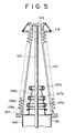
- FIG. 5 is a longitudinal sectional view of the bushing in the third embodiment.
- the bushing in the third embodiment similarly to the busing in the first embodiment shown in Figs. 1 and 2, is provided with a plurality of ring shields 107a, 107b and 107c, i.e., internal shields.
- the inside diameters of upper ones of the ring shields 107a, 107b and 107c are smaller than those of lower ones.
- the area of a surface on which electric field intensity is higher than a fixed value facing a central conductor 102 is reduced and therefore reliability in insulating performance can be improved.
- the top ring shield 107c is coated with an insulating coating, electric field intensity on the surface of the top ring shield 107c can be relieved.
- the distance between the top ring shield 107c and the central conductor 102 can be reduced which will increase the distance between the top ring shield 107c and an insulating tube, in this way, the electric field intensity in a tangential distribution on the surface of the insulating tube 101 can further be reduced and evenly distribution.
- FIG. 6 is a longitudinal sectional view of the bushing in the fourth embodiment.
- a plurality of ring shields 107a, 107b and 107c are connected by insulating support 111a, 111b and 111c.
- Potentials of upper ones of the ring shields 107a, 107b and 107c are higher than those of lower ones of the same due to capacitive potential distribution, and the voltage difference between a high-voltage central conductor 102 and the upper ring shield is smaller than lower ones. Accordingly, the inside diameters of the upper ones of the ring shields 107a, 107b and 107c may be smaller than those of the lower ones, and the internal shields may be of small diameters.
- electric field intensity on the surface of the insulating tube 101 of the bushing in the fourth embodiment is lower than that on the surface of the insulating tube 101 of the bushing shown in Fig. 5, the bushing can be made in a smaller diameter, corona discharge can be prevented or mitigated and withstand voltage will increased.
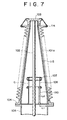
- FIG. 7 is a longitudinal sectional view of the bushing in the fifth embodiment.
- the fifth embodiment employs a composite insulating tube.
- the composite insulating tube is formed by fitting an inner insulating tube 115 of a FRP material in an outer nonceramic insulating tube 101a of weather-resistant rubber.
- the material covering the FRP insulating tube 115 is, for example, silicone rubber, EVA (ethylene-vinyl acetate), EPDM or EPR (ethylene propylene copolymer). It is possible that the lifetime of the bushing is shortened by the degradation of the composite insulating tube due to tracking or cracking caused by partial discharge or local arcing on the surface of the bushing. Since internal shields shown in Fig.
- the bushing in this embodiment is provided with a cylindrical shield 110 having a length L 2 along a central conductor greater than the distance L 1 between the insulating tube 115 and the coaxial cylindrical shield 110 to equalize the distribution of equipotential lines.
- the bushing in the fifth embodiment similarly to those shown in Figs. 1, 5 and 6, may be provided with a plurality of ring shields for better performance.
- FIG. 8 is a longitudinal sectional view of the bushing in the sixth embodiment employing a composite insulating tube similar to that employed in the bushing shown in Fig. 7.
- parts of the same materials are designated by the same reference characters.
- the composite insulating tube 115 has a cylindrical shape. Since the distribution of equipotential lines on the insulating tube 115 is evenly distribution by a coaxial cylindrical shield 110 and the ring shield 107, corona discharge and local arcing can be prevented, the reliability of the bushing can be enhanced and the shortening of the lifetime of the bushing can be avoided.
- FIG. 9 is a longitudinal sectional view of the bushing in the seventh embodiment employing a composite insulating tube similar to that employed in the bushing shown in Fig. 8.
- parts of the same materials are designated by the same reference characters.
- the overall shape of the bushing shown in Fig. 9 is different from that of the bushing shown in Fig. 8. As shown in Fig. 9, the bushing has a generally conical upper part forwards the high-voltage terminal. Since the bushing has the conical part on the side of the high-voltage terminal, the capacity of the composite insulating tube may be small and the distribution of equipotential lines around the part of the insulating tube on the side of the high-voltage terminal is more evenly distributed.
- the distribution of equipotential lines on the insulating tube can further be evenly distribution by forming the bushing of parts having different shapes, such as a first cylindrical part, a first conical part connected to the first cylindrical part, a second cylindrical part connected to the first conical part and a second conical part connected to the second cylindrical part.
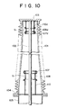
- FIG. 10 is a longitudinal sectional view of the bushing in the eighth embodiment.
- the bushing is provided with internal shields similar to those mentioned above in an upper part and a lower part thereof.
- a cylindrical shield 110d and a ring shield 107d similar to those mounted in the lower part of the bushing are mounted in the upper part of the bushing, electric field intensity in a tangential distribution on the surface of an upper part of the insulating tube can be reduced.
- the potential of the upper internal shields is equal to that of a high-voltage terminal 103. Therefore, any external shield ring corresponding to the external shield ring 114 mounted around the upper part of the insulating tube of the bushing shown in Fig. 3 is not necessary, therefore cost can be reduced.
- a composite insulating tube having an inner insulating tube of a FRP material heat radiated from a conductor can be intercepted by the internal shields and hence the temperature rise of the composite insulating tube can be suppressed.
- the bushing is provided internally with the plurality of shield rings arranged at intervals to relieve electric field intensity in a tangential distribution on the surface of the insulating tube. Therefore, corona discharge under wet condition can be prevented, antipollution performance is improved, and the effect of cooling the interior of the insulating tube can be improved. Any external shield is not necessary, the insulating tube may be formed in a small diameter and the cost can be reduced.
Abstract
Description
Claims (10)
- A bushing comprising: an insulating tube; a central conductor mounted inside the insulating tube; and a plurality of internal shields surrounding the central conductor;
characterized in that the plurality of internal shields are arranged at intervals along the axis of the central conductor with gaps therebetween and are supported on a conductive support. - The bushing according to claim 1, wherein the plurality of internal shields are kept at a ground potential.
- The bushing according to claim 1, wherein the internal shields are mounted so that the lengths of the gaps between the internal shields increase gradually toward a high-voltage terminal of the central conductor.
- The bushing according to claim 1, wherein the inside diameter of the internal shields decreases gradually toward a high-voltage terminal of the central conductor or the inside diameters of at least the internal shields near the high-voltage terminal of the central conductor are smaller.
- The bushing according to claim 1, wherein the plurality of internal shields are connected by insulating media.
- The bushing according to claim 1, wherein at least the internal shields near the high-voltage terminal of the central conductor are coated with an insulating coating.
- The bushing according to claim 1, wherein the high-voltage terminal of the central conductor is surrounded by a plurality of shields kept at a potential equal to the voltage of the high-voltage terminal of the central conductor and having a short length along the axis of the bushing, or by a cylindrical shield and short shields.
- The bushing according to claim 1, wherein at lest one of the plurality of internal shields is a ring shield having a toroidal shape.
- The bushing according to claim 1, wherein the insulating tube is a composite insulating tube.
- The bushing according to claim 1, wherein the internal shield on the side of the ground potential among the plurality of internal shields has a length along the central conductor greater than the distance between the inner surface of the insulating tube and the same internal shield.
Applications Claiming Priority (2)
| Application Number | Priority Date | Filing Date | Title |
|---|---|---|---|
| JP2295398 | 1998-02-04 | ||
| JP2295398 | 1998-02-04 |
Publications (2)
| Publication Number | Publication Date |
|---|---|
| EP0935259A2 true EP0935259A2 (en) | 1999-08-11 |
| EP0935259A3 EP0935259A3 (en) | 2000-10-18 |
Family
ID=12096988
Family Applications (1)
| Application Number | Title | Priority Date | Filing Date |
|---|---|---|---|
| EP99102171A Withdrawn EP0935259A3 (en) | 1998-02-04 | 1999-02-03 | Bushing |
Country Status (3)
| Country | Link |
|---|---|
| US (1) | US6218627B1 (en) |
| EP (1) | EP0935259A3 (en) |
| KR (1) | KR100505375B1 (en) |
Cited By (7)
| Publication number | Priority date | Publication date | Assignee | Title |
|---|---|---|---|---|
| DE10014679A1 (en) * | 2000-03-17 | 2001-10-04 | Siemens Ag | Implementation for an electrical high-voltage conductor |
| CN101136270A (en) * | 2006-08-31 | 2008-03-05 | Abb技术有限公司 | High voltage bushing |
| CN103443875A (en) * | 2011-03-16 | 2013-12-11 | Abb技术有限公司 | High voltage bushing having support used for conductor |
| CN104795189A (en) * | 2015-03-09 | 2015-07-22 | 江苏安靠智能输电工程科技股份有限公司 | Ultrahigh pressure gas insulating composite sleeve |
| CN106128659A (en) * | 2016-08-15 | 2016-11-16 | 江苏智达高压电气有限公司 | A kind of extra-high voltage electroceramics external insulation outlet sleeve |
| WO2018036082A1 (en) * | 2016-08-22 | 2018-03-01 | 江苏智达高压电气有限公司 | Ultra-high-voltage direct current wall bushing |
| WO2018036083A1 (en) * | 2016-08-22 | 2018-03-01 | 江苏智达高压电气有限公司 | Novel structure extra-high-voltage direct current transformer bushing |
Families Citing this family (16)
| Publication number | Priority date | Publication date | Assignee | Title |
|---|---|---|---|---|
| US6346677B1 (en) * | 1999-09-08 | 2002-02-12 | Electro Composites, Inc. | High-voltage bushing provided with external shields |
| US6951987B1 (en) | 2003-01-31 | 2005-10-04 | United States Of America As Represented By The Secretary Of The Navy | High voltage bushing |
| US20060157269A1 (en) * | 2005-01-18 | 2006-07-20 | Kopp Alvin B | Methods and apparatus for electric bushing fabrication |
| US7994427B2 (en) * | 2006-03-24 | 2011-08-09 | Abb Technology Ltd. | High voltage insulation system and a method of manufacturing same |
| DE102006038221B4 (en) * | 2006-08-03 | 2009-03-26 | Siemens Ag | Device for electrical shielding of a high voltage feedthrough |
| CN101136269B (en) * | 2006-08-31 | 2013-03-27 | Abb研究有限公司 | High voltage bushing |
| US7807930B1 (en) * | 2007-11-30 | 2010-10-05 | The United States Of America As Represented By The Secretary Of The Navy | High-voltage feed-through bushing with internal and external electric field grading elements |
| DE102009031598B4 (en) * | 2009-07-06 | 2011-06-01 | Siemens Aktiengesellschaft | Vacuum interrupter |
| WO2012004289A1 (en) * | 2010-07-08 | 2012-01-12 | Abb Research Ltd | High voltage shielding device and a system comprising the same |
| CN103824663A (en) * | 2014-03-04 | 2014-05-28 | 上海思源高压开关有限公司 | High-tension bushing and shield body thereof |
| CN106300216B (en) * | 2015-05-19 | 2019-06-14 | 泰科电子(上海)有限公司 | Insulate terminal assembly |
| CN106159845B (en) * | 2016-08-15 | 2018-01-26 | 江苏智达高压电气有限公司 | A kind of extra-high voltage SF6 gas-insulated wall bushings |
| CN107170539A (en) * | 2017-03-22 | 2017-09-15 | 特变电工中发上海高压开关有限公司 | A kind of 800kV sleeve pipes with apical ring shielding construction |
| EP3618086B1 (en) | 2018-08-30 | 2021-04-28 | ABB Power Grids Switzerland AG | Shield for a terminal of a high-voltage electrical device and method for operating the same |
| DE102019214006A1 (en) * | 2019-09-13 | 2021-03-18 | Siemens Energy Global GmbH & Co. KG | Cover unit for a converter head of a high-voltage converter device, converter head and high-voltage converter device |
| EP3955266A1 (en) * | 2020-08-12 | 2022-02-16 | Hitachi Energy Switzerland AG | Wall bushing |
Citations (2)
| Publication number | Priority date | Publication date | Assignee | Title |
|---|---|---|---|---|
| DD108003A1 (en) * | 1973-10-17 | 1974-08-20 | ||
| US4159401A (en) * | 1977-11-01 | 1979-06-26 | Tokyo Shibaura Kenki K.K. | Gas filled bushings with potential shields |
Family Cites Families (11)
| Publication number | Priority date | Publication date | Assignee | Title |
|---|---|---|---|---|
| US3686600A (en) * | 1971-02-22 | 1972-08-22 | Westinghouse Electric Corp | Potential transformer |
| US3792214A (en) * | 1972-01-28 | 1974-02-12 | Westinghouse Electric Corp | Vacuum interrupter for high voltage application |
| JPS6016690B2 (en) * | 1978-02-23 | 1985-04-26 | 株式会社東芝 | oil-filled bushing |
| US4431859A (en) * | 1980-11-27 | 1984-02-14 | Mitsubishi Denki Kabushiki Kaisha | Bushing for gas-insulated electrical equipment |
| JPS57103213A (en) * | 1980-12-19 | 1982-06-26 | Tokyo Shibaura Electric Co | Gas insulating bushing |
| JPS58163111A (en) | 1982-03-23 | 1983-09-27 | 株式会社日立製作所 | Bushing |
| JPS6086709A (en) | 1983-10-19 | 1985-05-16 | 株式会社東芝 | Bushing |
| JPS6136006A (en) | 1984-07-27 | 1986-02-20 | Toyota Motor Corp | Shock absorptive connection construction of bar-shaped suspension member |
| JPS62211813A (en) * | 1986-03-12 | 1987-09-17 | 三菱電機株式会社 | Gas-filled bushing |
| DE4240118C1 (en) * | 1992-11-30 | 1994-03-31 | Ritz Messwandler Kg | Execution, especially for high voltages with a special electrode holder |
| US5466891A (en) | 1994-04-08 | 1995-11-14 | Abb Power T&D Company Inc. | Conical composite SF6 high voltage bushing with floating shield |
-
1999
- 1999-02-02 US US09/241,632 patent/US6218627B1/en not_active Expired - Lifetime
- 1999-02-03 KR KR10-1999-0003495A patent/KR100505375B1/en not_active IP Right Cessation
- 1999-02-03 EP EP99102171A patent/EP0935259A3/en not_active Withdrawn
Patent Citations (2)
| Publication number | Priority date | Publication date | Assignee | Title |
|---|---|---|---|---|
| DD108003A1 (en) * | 1973-10-17 | 1974-08-20 | ||
| US4159401A (en) * | 1977-11-01 | 1979-06-26 | Tokyo Shibaura Kenki K.K. | Gas filled bushings with potential shields |
Cited By (14)
| Publication number | Priority date | Publication date | Assignee | Title |
|---|---|---|---|---|
| DE10014679A1 (en) * | 2000-03-17 | 2001-10-04 | Siemens Ag | Implementation for an electrical high-voltage conductor |
| CN101136270B (en) * | 2006-08-31 | 2013-03-20 | Abb技术有限公司 | High voltage bushing and its production method and high voltage apparatus |
| WO2008027004A1 (en) * | 2006-08-31 | 2008-03-06 | Abb Technology Ltd | High voltage bushing |
| EP2057644A1 (en) * | 2006-08-31 | 2009-05-13 | ABB Technology Ltd | High voltage bushing |
| EP2057644A4 (en) * | 2006-08-31 | 2012-03-14 | Abb Technology Ltd | High voltage bushing |
| US8389876B2 (en) | 2006-08-31 | 2013-03-05 | Abb Technology Ltd. | High voltage bushing |
| CN101136270A (en) * | 2006-08-31 | 2008-03-05 | Abb技术有限公司 | High voltage bushing |
| CN103443875A (en) * | 2011-03-16 | 2013-12-11 | Abb技术有限公司 | High voltage bushing having support used for conductor |
| CN103443875B (en) * | 2011-03-16 | 2016-02-17 | Abb技术有限公司 | There is the high voltage bushing of the support for conductor |
| CN104795189A (en) * | 2015-03-09 | 2015-07-22 | 江苏安靠智能输电工程科技股份有限公司 | Ultrahigh pressure gas insulating composite sleeve |
| CN106128659A (en) * | 2016-08-15 | 2016-11-16 | 江苏智达高压电气有限公司 | A kind of extra-high voltage electroceramics external insulation outlet sleeve |
| CN106128659B (en) * | 2016-08-15 | 2018-07-13 | 江苏智达高压电气有限公司 | A kind of extra-high voltage electroceramics external insulation outlet sleeve |
| WO2018036082A1 (en) * | 2016-08-22 | 2018-03-01 | 江苏智达高压电气有限公司 | Ultra-high-voltage direct current wall bushing |
| WO2018036083A1 (en) * | 2016-08-22 | 2018-03-01 | 江苏智达高压电气有限公司 | Novel structure extra-high-voltage direct current transformer bushing |
Also Published As
| Publication number | Publication date |
|---|---|
| US6218627B1 (en) | 2001-04-17 |
| KR19990072388A (en) | 1999-09-27 |
| EP0935259A3 (en) | 2000-10-18 |
| KR100505375B1 (en) | 2005-07-29 |
Similar Documents
| Publication | Publication Date | Title |
|---|---|---|
| US6218627B1 (en) | Bushing | |
| US5406030A (en) | High voltage, high-current power cable termination with single condenser grading stack | |
| EP2057644B1 (en) | High voltage bushing | |
| US4296274A (en) | High voltage bushing having weathershed and surrounding stress relief collar | |
| US4272642A (en) | Gas-insulated high-voltage bushing with shield electrode embedded in an annular insulating body | |
| US4774385A (en) | Electrical bushing for use with a gas insulated electrical apparatus | |
| US8088996B2 (en) | High voltage DC bushing and device comprising such high voltage bushing | |
| CA1130370A (en) | Enclosed-type zinc-oxide surge arrester | |
| EP0429843B1 (en) | Bushing for high direct voltages | |
| US3842318A (en) | Shielded metal enclosed electrical equipment | |
| RU2252463C2 (en) | Cathode-ray tube capacitor and cathode-ray tube | |
| US4540967A (en) | Molded transformer with grounded electrically conductive layer | |
| EP0413103B1 (en) | Condenser type barrier | |
| US4328391A (en) | Gas insulated transmission line having tapered particle trapping ring | |
| JP3161027B2 (en) | Gas insulated current transformer | |
| WO1980000287A1 (en) | Improved air entrance bushing for gas-insulated bus | |
| US4780577A (en) | Electrical bushing of a gas insulated electrical apparatus | |
| JP3769961B2 (en) | Bushing | |
| CN100355173C (en) | Discoid support insulator for a three-phase encapsulated high-voltage installation | |
| US5227584A (en) | Barrier of condenser type for field control in transformer bushing terminals | |
| US4403104A (en) | Gas-insulated bushing having minimized throat diameter | |
| US11929227B1 (en) | Multi-contact disconnect switch for lightning arrester | |
| JPS5924482B2 (en) | butsing | |
| KR19980087480A (en) | Tank type lightning arrester | |
| JPH06223656A (en) | Gas bushing |
Legal Events
| Date | Code | Title | Description |
|---|---|---|---|
| PUAI | Public reference made under article 153(3) epc to a published international application that has entered the european phase |
Free format text: ORIGINAL CODE: 0009012 |
|
| AK | Designated contracting states |
Kind code of ref document: A2 Designated state(s): AT BE CH CY DE DK ES FI FR GB GR IE IT LI LU MC NL PT SE |
|
| AX | Request for extension of the european patent |
Free format text: AL;LT;LV;MK;RO;SI |
|
| RIN1 | Information on inventor provided before grant (corrected) |
Inventor name: YAMAGIWA, TOKIO Inventor name: ENDO, FUMIHIRO Inventor name: ROKUNOHE, TOSHIAKI Inventor name: SHINDO, KATSUJI |
|
| PUAL | Search report despatched |
Free format text: ORIGINAL CODE: 0009013 |
|
| AK | Designated contracting states |
Kind code of ref document: A3 Designated state(s): AT BE CH CY DE DK ES FI FR GB GR IE IT LI LU MC NL PT SE |
|
| AX | Request for extension of the european patent |
Free format text: AL;LT;LV;MK;RO;SI |
|
| AKX | Designation fees paid | ||
| REG | Reference to a national code |
Ref country code: DE Ref legal event code: 8566 |
|
| STAA | Information on the status of an ep patent application or granted ep patent |
Free format text: STATUS: THE APPLICATION IS DEEMED TO BE WITHDRAWN |
|
| 18D | Application deemed to be withdrawn |
Effective date: 20010419 |