EP0935162B1 - Kameraobjektiv, Kamera mit einem derartigen Objektiv und Verfahren zur Herstellung einer derartigen Kamera - Google Patents
Kameraobjektiv, Kamera mit einem derartigen Objektiv und Verfahren zur Herstellung einer derartigen Kamera Download PDFInfo
- Publication number
- EP0935162B1 EP0935162B1 EP19980102004 EP98102004A EP0935162B1 EP 0935162 B1 EP0935162 B1 EP 0935162B1 EP 19980102004 EP19980102004 EP 19980102004 EP 98102004 A EP98102004 A EP 98102004A EP 0935162 B1 EP0935162 B1 EP 0935162B1
- Authority
- EP
- European Patent Office
- Prior art keywords
- lens
- lens assembly
- camera
- case
- objective
- Prior art date
- Legal status (The legal status is an assumption and is not a legal conclusion. Google has not performed a legal analysis and makes no representation as to the accuracy of the status listed.)
- Expired - Lifetime
Links
- 238000000034 method Methods 0.000 title claims description 3
- 239000000463 material Substances 0.000 claims description 15
- 230000003287 optical effect Effects 0.000 claims description 13
- 229910052594 sapphire Inorganic materials 0.000 claims description 10
- 239000010980 sapphire Substances 0.000 claims description 10
- 239000005341 toughened glass Substances 0.000 claims description 4
- 238000004519 manufacturing process Methods 0.000 claims description 3
- 239000002245 particle Substances 0.000 claims 1
- 239000012780 transparent material Substances 0.000 claims 1
- 238000009825 accumulation Methods 0.000 description 4
- 239000011521 glass Substances 0.000 description 3
- 238000004140 cleaning Methods 0.000 description 2
- 239000003082 abrasive agent Substances 0.000 description 1
- 229920001893 acrylonitrile styrene Polymers 0.000 description 1
- 238000004026 adhesive bonding Methods 0.000 description 1
- 230000004075 alteration Effects 0.000 description 1
- 238000000149 argon plasma sintering Methods 0.000 description 1
- 230000015572 biosynthetic process Effects 0.000 description 1
- 239000002131 composite material Substances 0.000 description 1
- 238000010276 construction Methods 0.000 description 1
- 239000013078 crystal Substances 0.000 description 1
- 230000007547 defect Effects 0.000 description 1
- 230000001627 detrimental effect Effects 0.000 description 1
- 230000000694 effects Effects 0.000 description 1
- 230000002349 favourable effect Effects 0.000 description 1
- 230000005693 optoelectronics Effects 0.000 description 1
- SCUZVMOVTVSBLE-UHFFFAOYSA-N prop-2-enenitrile;styrene Chemical compound C=CC#N.C=CC1=CC=CC=C1 SCUZVMOVTVSBLE-UHFFFAOYSA-N 0.000 description 1
- 230000003678 scratch resistant effect Effects 0.000 description 1
- 230000035939 shock Effects 0.000 description 1
- 210000000707 wrist Anatomy 0.000 description 1
Images

Classifications
-
- G—PHYSICS
- G03—PHOTOGRAPHY; CINEMATOGRAPHY; ANALOGOUS TECHNIQUES USING WAVES OTHER THAN OPTICAL WAVES; ELECTROGRAPHY; HOLOGRAPHY
- G03B—APPARATUS OR ARRANGEMENTS FOR TAKING PHOTOGRAPHS OR FOR PROJECTING OR VIEWING THEM; APPARATUS OR ARRANGEMENTS EMPLOYING ANALOGOUS TECHNIQUES USING WAVES OTHER THAN OPTICAL WAVES; ACCESSORIES THEREFOR
- G03B29/00—Combinations of cameras, projectors or photographic printing apparatus with non-photographic non-optical apparatus, e.g. clocks or weapons; Cameras having the shape of other objects
Definitions
- the present invention relates to a lens for a camera, for example a camera or a camera.
- objectives comprise a frame and at least one lens, one of the faces of which defines the external surface of the objective.
- the chassis of such lenses is generally cylindrical in shape and extends outward beyond the outer surface of the lens.
- the angle formed together the connection surfaces of the chassis and the lens is generally close to 90 °. In this way, the lens is protected by the end of the frame.
- the surfaces of connection of the chassis and the lens define a throat in which dirt can accumulate.
- it is usually planned to cover the goal by means of a removable cap.
- Such a measure allows to delay this accumulation, but in no case avoid it.
- cleaning the throat requires precautions and can hardly be perfect until background.
- Examples of conventional devices are disclosed in: JP-A-09-105871, DE-U-85 24 682, FR-A-1 167 779, FR-A-2 671 411, JP-A-58-083 837.
- the main purpose of the invention is to avoid the accumulation of dirt on the external surface of the lens, without exposing it to the formation of scratches.
- the invention therefore relates to a lens for camera, according to rev. 1.
- the objective remains clean, the absence of crevices to avoid accumulation of dirt.
- the hardness of the lens material defining the outer surface of the lens is greater than or equal to that of glass soaked, it is practically scratch-resistant.
- the objective comprises a first lens, front, a second intermediate lens, and a third lens, posterior.
- the front lenses and posterior are convergent and are made with materials with a refractive index and a number of Abbe as high as possible.
- the intermediate lens is divergent and it is made of a material having as low an Abbe number as possible. Such a structure compensates for aberrations chromatic.
- the invention also aims to achieve a camera according to rev. 6 particularly robust and quality.
- the invention also relates to a method according to rev. 8 for the manufacture of a camera according to rev. 6 to obtain perfectly continuous surfaces despite the causes the lens to be attached to the camera.
- the invention finally relates to a device for taking views of very small dimensions of which the case is that a wristwatch which will be described later on more in detail by way of example and designated for convenience by "Camera show.”
- anterior the parts at the front of the lens, outside the camera.
- the parts “posterior” are instead placed at the back of the lens, inside the camera.
- radial and axial refer to the optical axis of the objective.
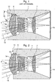
- the known objectives include a frame 1 of form tubular and cylindrical, housing inside a set of lenses, for example comprising a front lens 3 convergent, one of the faces of which 31 defines the surface objective lens 2, posterior lens 4 convergent, as well as an intermediate lens 5 divergent.
- This objective 2 makes it possible to focus the rays 18 on a photosensitive surface 19.
- chassis 1 has surfaces cylindrical and flat. Cylindrical surfaces, bearing references 6, 7 and 8 respectively provide the radial positioning of lenses 3, 4 and 5.
- the flat surfaces with references 9, 10 and 11 define axial positioning surfaces for position lenses 3, 4 and 5 respectively.
- Lenses 3, 4 and 5 are fixed to the frame by known means, not shown in the drawing, for example by gluing or by means of threaded rings cooperating with threads made in the chassis.
- the chassis 1 extends forward to form a flange 12, which extends at least to the end of lens 3, to protect it from bodies that could possibly get in touch with it.
- this angle is generally less than 90 °.
- the objective according to the invention represented in the figure 2 also includes a chassis 1 and a composite optic of the same lens assembly.
- Frame 1 defines the same positioning surfaces 6 to 11 for position lenses 3, 4 and 5. It differs from the objective of FIG. 1 by the fact that it does not include no collar.
- the chassis 1 has a front face 15 flat and contiguous to the surface 3a of the lens 3.
- the face 15 and the surface 3a together define a obtuse angle ⁇ , close to 180 °. It is in any case greater than 120 °. We can easily understand that in these conditions it is practically impossible for it to accumulate a deposit likely to affect the quality of the objective. If, despite everything, dirt adheres to the surface 3a, it is considerably easier to clean. In case such a lens is mounted in a device attached to the wrist of the user, for example when such a device is integrated in a wristwatch, cleaning is done almost automatically, by rubbing clothes on the surface 3a.
- the front lens 3 and the lens posterior 4, both convergent, are made in a material with a high Abbe number (v).
- the lens intermediate 5 is divergent and made of a material having a low Abbe number.
- the converging lenses 3 and 4 have an index of refraction as high as possible and that the lens divergent has a refractive index as low as possible.
- PMMA polymethyl-metha-acrylate
- SAN acrylonitrile styrene
- R1 is the radius of curvature of the front side of a lens
- R2 is the radius of curvature of the posterior surface
- ⁇ its diameter is the radius of curvature of the posterior surface
- d the distance on the optical axis of a lens with the next one, or with the surface photosensitive for lens 4.
- the objective realized on this base presents an angle opening of 20 °, for a distance of 11.68 mm between the surface 3a and the photosensitive surface 19, on which the image of the object to be photographed must be drawn.
- the focal length is 10.50 mm.
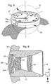
- a watch fitted with a device includes a rectangular box 20, closed at its upper part by a glass 26 arranged above a dial 27 which supports a display cell 28.
- a lens 22 is mounted in the wall of the housing 20. It has the same characteristics as the lens described in figure 2. It has a front lens 23, a posterior lens 24 and a lens intermediate 25. More specifically, objective 22 is mounted in a chassis 21, comparable to chassis 1 of Figure 2, fixed in the housing 20, with an axis substantially parallel to the front face of the glass 26.
- Objective 22 has an anterior face formed of the surface 23a of the lens 23 and of the surface 21a of the frame 21 adjacent to lens 23.
- An optoelectronic device 29 is placed at the back of lens 22. It turns light into electrical signals. These signals are processed by a electronic circuit schematically represented at 30, which controls both the watch and the hand-held device view.
- the electronic circuit 30 is notably connected to the display cell 28 which acts as a viewfinder.
- the lens 23 is slightly prominent. Its surface 23a forms with the surface 21a of the chassis 21 an obtuse angle ⁇ , greater than 120 °. As one can easily imagine, this angle does not does not allow the accumulation of dirt.
- the device differs from that shown in Figures 3 and 4 essentially by the fact that the surface 23a of the front lens 23 fits perfectly into the housing surface 20.
- the outer surface device 20a of the case 20 corresponding to the middle of the watch, fits into a sphere 31 represented by dashed in Figure 5.
- the radius R of this sphere is substantially equal to that of the spherical surface defining the anterior face 23a of the front lens 23.
- the housing 20 and the lens 23 define a continuous surface without crevices or roughness likely to encourage fouling in the part of the housing 20 carrying the lens 23.
- the lens 23 can be in tempered glass, but more advantageously in sapphire. Of the so, the hardness of lens 23 is sufficient to avoid any scratch both during the final operation than in normal conditions of use. We can note that it could have been possible to achieve a goal with a flat sapphire window and lenses placed at the back of this window. The tests have shown that the price remains substantially the same, that the optical quality is worse and that the lens length is greater.
- the lens will be machined in the crystal in an orientation ensuring a refractive index constant, regardless of the angle of incidence of a ray luminous.
- the optical axis of the sapphire will be confused with the axis of the objective.
- the camera as described presents a favorable configuration, both in terms of optical as well as mechanical characteristics. He can so be used in particularly conditions hard, without however its performance being affected.
Landscapes
- Physics & Mathematics (AREA)
- General Physics & Mathematics (AREA)
- Lenses (AREA)
Claims (8)
- Objektiv für eine Bildaufnahmevorrichtung, mit einer Fassung (1; 21) und einer Optik, die aus wenigstens einer Frontlinse (3, 23) gebildet ist, deren eine Seite (3a; 23a) die vordere Oberfläche des Objektivs bildet, bei dem die Seite (3a; 23a) mit der Fassung (1; 21) einen Verbindungswinkel (α) festlegt, dessen Wert größer oder gleich 120° ist, dadurch gekennzeichnet, daß die Frontlinse (3; 23) aus einem transparenten Material besteht, dessen Härte größer oder gleich derjenigen von Hartglas ist.
- Objektiv nach Anspruch 1, dadurch gekennzeichnet, daß die Frontlinse (3; 23) konvergierend ist.
- Objektiv nach Anspruch 1 oder 2, dadurch gekennzeichnet, daß die vordere Oberfläche (3a; 23a) der Frontlinse (3; 23) und die Fassung (1; 21) zusammen eine ununterbrochene Oberfläche bilden.
- Objektiv nach Anspruch 1, dadurch gekennzeichnet, daß das Material Saphir oder Hartglas ist.
- Objektiv nach Anspruch 2, dadurch gekennzeichnet, daß die Optik des Objektivs ferner eine hintere konvergierende Linse (4; 24) und eine Zwischenlinse (5; 25) aufweist, wobei die Linsen auf die erste Linse (3; 23) ausgerichtet sind, und die Zwischenlinse (5; 25) divergierend ist und aus einem Material besteht, das eine Abbe-Zahl aufweist, die kleiner ist als diejenige, die die Materialien aufweisen, die die konvergenten Linsen bilden (3, 4; 23, 24).
- Bildaufnahmevorrichtung, die ein Gehäuse (20) umfaßt und mit einem Objektiv (22) nach einem der vorhergehenden Ansprüche versehen ist, das fest in einer Wandung des Gehäuses (20) montiert ist, wobei in der Vorrichtung wenigstens der Abschnitt des Gehäuses, in dem das Objektiv (22) montiert ist, und die vordere Oberfläche (23a) der Frontlinse (23) zusammen eine im wesentlichen sphärische Oberfläche bilden.
- Bildaufnahmevorrichtung nach Anspruch 6, dadurch gekennzeichnet, daß das Gehäuse (20) das Gehäuse einer Armbanduhr ist.
- Verfahren zum Herstellen einer Vorrichtung nach Anspruch 6, wobei bei dem Verfahren wenigstens die Oberfläche des Gehäuses (20), in der das Objektiv (22) montiert ist, nach Montage des Objektivs durch Abrasion mittels Partikel bearbeitet wird, deren Härte kleiner ist, als diejenige des Materials, das die Frontlinse (3; 23) bildet.
Priority Applications (2)
| Application Number | Priority Date | Filing Date | Title |
|---|---|---|---|
| DE69817751T DE69817751D1 (de) | 1998-02-05 | 1998-02-05 | Kameraobjektiv, Kamera mit einem derartigen Objektiv und Verfahren zur Herstellung einer derartigen Kamera |
| EP19980102004 EP0935162B1 (de) | 1998-02-05 | 1998-02-05 | Kameraobjektiv, Kamera mit einem derartigen Objektiv und Verfahren zur Herstellung einer derartigen Kamera |
Applications Claiming Priority (1)
| Application Number | Priority Date | Filing Date | Title |
|---|---|---|---|
| EP19980102004 EP0935162B1 (de) | 1998-02-05 | 1998-02-05 | Kameraobjektiv, Kamera mit einem derartigen Objektiv und Verfahren zur Herstellung einer derartigen Kamera |
Publications (2)
| Publication Number | Publication Date |
|---|---|
| EP0935162A1 EP0935162A1 (de) | 1999-08-11 |
| EP0935162B1 true EP0935162B1 (de) | 2003-09-03 |
Family
ID=8231357
Family Applications (1)
| Application Number | Title | Priority Date | Filing Date |
|---|---|---|---|
| EP19980102004 Expired - Lifetime EP0935162B1 (de) | 1998-02-05 | 1998-02-05 | Kameraobjektiv, Kamera mit einem derartigen Objektiv und Verfahren zur Herstellung einer derartigen Kamera |
Country Status (2)
| Country | Link |
|---|---|
| EP (1) | EP0935162B1 (de) |
| DE (1) | DE69817751D1 (de) |
Families Citing this family (2)
| Publication number | Priority date | Publication date | Assignee | Title |
|---|---|---|---|---|
| JP2001251542A (ja) * | 1999-12-28 | 2001-09-14 | Casio Comput Co Ltd | 携帯型撮像機器 |
| EP1180718A1 (de) * | 2000-08-11 | 2002-02-20 | EM Microelectronic-Marin SA | Vorrichtung zur Aufnahme von Bildern kleiner Abmessungen, insbesondere Photoapparat oder Videokamera |
Family Cites Families (5)
| Publication number | Priority date | Publication date | Assignee | Title |
|---|---|---|---|---|
| FR1167779A (fr) * | 1956-11-09 | 1958-11-28 | Centre Nat Rech Scient | Hublot correcteur à grand champ pour prises de vues sous-marines |
| JPS5883837A (ja) * | 1981-11-14 | 1983-05-19 | Gen Eng:Kk | 光学装置付き装身具 |
| DE8524682U1 (de) * | 1985-08-29 | 1985-12-05 | PK Electronic Produktionsgesellschaft mbH & Co KG, 2000 Hamburg | Armbanduhr |
| FR2671411A1 (fr) * | 1991-01-09 | 1992-07-10 | Savona Jean Louis | Montre-bracelet photographique dotee d'un dispositif miniaturise permettant d'obtenir plusieurs negatifs photographiques. |
| JPH09105871A (ja) * | 1995-10-13 | 1997-04-22 | Olympus Optical Co Ltd | 光学コンポーネント |
-
1998
- 1998-02-05 EP EP19980102004 patent/EP0935162B1/de not_active Expired - Lifetime
- 1998-02-05 DE DE69817751T patent/DE69817751D1/de not_active Expired - Lifetime
Also Published As
| Publication number | Publication date |
|---|---|
| DE69817751D1 (de) | 2003-10-09 |
| EP0935162A1 (de) | 1999-08-11 |
Similar Documents
| Publication | Publication Date | Title |
|---|---|---|
| WO1999057613A1 (fr) | Masse de remontage oscillante pour piece d'horlogerie a mouvement automatique et piece d'horlogerie equipee d'une telle masse de remontage | |
| EP0282766A1 (de) | Aktives optisches Steckergehäuse | |
| EP0944845B1 (de) | Vorrichtung zur lokalisierung von strahlungsquellen | |
| CH687495B5 (fr) | Montre comprenant un dispositif d'affichage associé à un dispositif optique de grossissement. | |
| FR2677466A1 (fr) | Dispositif de detection de mise au point. | |
| EP2064584B1 (de) | Elektronische anzeigenanordnung | |
| WO2006095107A1 (fr) | Imageur optique destine a la realisation d'un afficheur optique | |
| EP1960827B1 (de) | Augenoptisches display | |
| FR2662517A1 (fr) | Viseur a image reelle pour appareil photographique a objectif zoom. | |
| FR2558604A1 (fr) | Fibroscope | |
| EP0935162A1 (de) | Kameraobjektiv, Kamera mit einem derartigen Objektiv und Verfahren zur Herstellung einer derartigen Kamera | |
| EP4413741A1 (de) | Infrarot-bildgebungsvorrichtung | |
| EP0976004B1 (de) | Optische Architektur für infrarotes Betrachtungssystem | |
| EP1046933B1 (de) | Optische Vorrichtung mit Absorptionsgradient und selektiver spektraler Filtrierung, und Objektiv und Kamera mit dieser Vorrichtung | |
| CH328493A (fr) | Dispositif pour augmenter la profondeur du champ d'un objectif | |
| FR2681153A1 (fr) | Viseur a focale variable. | |
| EP4170411B1 (de) | Vergrösserungsvorrichtung mit mehrfacher vergrösserung | |
| FR2593616A1 (fr) | Bague avec obturateur integre, en particulier pour prise de vues | |
| BE1004213A5 (fr) | Dispositif detecteur de trame. | |
| JPH11281867A (ja) | 写真機用レンズ組立体、そのようなレンズ組立体を含む写真機、およびそれらの製造方法 | |
| EP1766457A1 (de) | Ophthalmologische anzeige mit fokuseinstellungsvorrichtung | |
| Arnulf | Spectrographes à grande ouverture applicables à l'ultraviolet et à l'infrarouge | |
| FR3100896A1 (fr) | Appareil et procédé pour la capture d’image d’un objet observé | |
| EP0950909B1 (de) | Lichtsammelndes optisches System, das ein Objektiv mit mehreren Brennweiten bildet | |
| CH719077A9 (fr) | Dispositif grossissant à grossissement multiple. |
Legal Events
| Date | Code | Title | Description |
|---|---|---|---|
| PUAI | Public reference made under article 153(3) epc to a published international application that has entered the european phase |
Free format text: ORIGINAL CODE: 0009012 |
|
| AK | Designated contracting states |
Kind code of ref document: A1 Designated state(s): CH DE FR GB GR IT LI NL |
|
| AX | Request for extension of the european patent |
Free format text: AL;LT;LV;MK;RO;SI |
|
| 17P | Request for examination filed |
Effective date: 20000211 |
|
| AKX | Designation fees paid |
Free format text: CH DE FR GB GR IT LI NL |
|
| GRAH | Despatch of communication of intention to grant a patent |
Free format text: ORIGINAL CODE: EPIDOS IGRA |
|
| GRAS | Grant fee paid |
Free format text: ORIGINAL CODE: EPIDOSNIGR3 |
|
| GRAA | (expected) grant |
Free format text: ORIGINAL CODE: 0009210 |
|
| AK | Designated contracting states |
Kind code of ref document: B1 Designated state(s): CH DE FR GB GR IT LI NL |
|
| PG25 | Lapsed in a contracting state [announced via postgrant information from national office to epo] |
Ref country code: NL Free format text: LAPSE BECAUSE OF FAILURE TO SUBMIT A TRANSLATION OF THE DESCRIPTION OR TO PAY THE FEE WITHIN THE PRESCRIBED TIME-LIMIT Effective date: 20030903 Ref country code: IT Free format text: LAPSE BECAUSE OF FAILURE TO SUBMIT A TRANSLATION OF THE DESCRIPTION OR TO PAY THE FEE WITHIN THE PRE;WARNING: LAPSES OF ITALIAN PATENTS WITH EFFECTIVE DATE BEFORE 2007 MAY HAVE OCCURRED AT ANY TIME BEFORE 2007. THE CORRECT EFFECTIVE DATE MAY BE DIFFERENT FROM THE ONE RECORDED.SCRIBED TIME-LIMIT Effective date: 20030903 Ref country code: GB Free format text: LAPSE BECAUSE OF FAILURE TO SUBMIT A TRANSLATION OF THE DESCRIPTION OR TO PAY THE FEE WITHIN THE PRESCRIBED TIME-LIMIT Effective date: 20030903 |
|
| REG | Reference to a national code |
Ref country code: GB Ref legal event code: FG4D Free format text: NOT ENGLISH |
|
| REG | Reference to a national code |
Ref country code: CH Ref legal event code: EP |
|
| REF | Corresponds to: |
Ref document number: 69817751 Country of ref document: DE Date of ref document: 20031009 Kind code of ref document: P |
|
| PG25 | Lapsed in a contracting state [announced via postgrant information from national office to epo] |
Ref country code: GR Free format text: LAPSE BECAUSE OF FAILURE TO SUBMIT A TRANSLATION OF THE DESCRIPTION OR TO PAY THE FEE WITHIN THE PRESCRIBED TIME-LIMIT Effective date: 20031203 |
|
| PG25 | Lapsed in a contracting state [announced via postgrant information from national office to epo] |
Ref country code: DE Free format text: LAPSE BECAUSE OF FAILURE TO SUBMIT A TRANSLATION OF THE DESCRIPTION OR TO PAY THE FEE WITHIN THE PRESCRIBED TIME-LIMIT Effective date: 20031204 |
|
| NLV1 | Nl: lapsed or annulled due to failure to fulfill the requirements of art. 29p and 29m of the patents act | ||
| PG25 | Lapsed in a contracting state [announced via postgrant information from national office to epo] |
Ref country code: LI Free format text: LAPSE BECAUSE OF NON-PAYMENT OF DUE FEES Effective date: 20040229 Ref country code: CH Free format text: LAPSE BECAUSE OF NON-PAYMENT OF DUE FEES Effective date: 20040229 |
|
| GBV | Gb: ep patent (uk) treated as always having been void in accordance with gb section 77(7)/1977 [no translation filed] |
Effective date: 20030903 |
|
| PLBE | No opposition filed within time limit |
Free format text: ORIGINAL CODE: 0009261 |
|
| STAA | Information on the status of an ep patent application or granted ep patent |
Free format text: STATUS: NO OPPOSITION FILED WITHIN TIME LIMIT |
|
| 26N | No opposition filed |
Effective date: 20040604 |
|
| REG | Reference to a national code |
Ref country code: CH Ref legal event code: PL |
|
| PG25 | Lapsed in a contracting state [announced via postgrant information from national office to epo] |
Ref country code: FR Free format text: LAPSE BECAUSE OF NON-PAYMENT OF DUE FEES Effective date: 20041029 |
|
| REG | Reference to a national code |
Ref country code: FR Ref legal event code: ST |