EP0935084A2 - Gear shift lever for a motor vehicle - Google Patents
Gear shift lever for a motor vehicle Download PDFInfo
- Publication number
- EP0935084A2 EP0935084A2 EP99810013A EP99810013A EP0935084A2 EP 0935084 A2 EP0935084 A2 EP 0935084A2 EP 99810013 A EP99810013 A EP 99810013A EP 99810013 A EP99810013 A EP 99810013A EP 0935084 A2 EP0935084 A2 EP 0935084A2
- Authority
- EP
- European Patent Office
- Prior art keywords
- gear lever
- shift lever
- intermediate layer
- gear
- lever
- Prior art date
- Legal status (The legal status is an assumption and is not a legal conclusion. Google has not performed a legal analysis and makes no representation as to the accuracy of the status listed.)
- Withdrawn
Links
- 229920002725 thermoplastic elastomer Polymers 0.000 claims abstract description 16
- 229920001296 polysiloxane Polymers 0.000 claims abstract description 15
- 238000013016 damping Methods 0.000 claims abstract description 7
- 239000004033 plastic Substances 0.000 claims description 10
- 238000001746 injection moulding Methods 0.000 claims description 8
- 229920001971 elastomer Polymers 0.000 claims description 6
- 239000000806 elastomer Substances 0.000 claims description 3
- 239000002184 metal Substances 0.000 claims description 3
- 239000004636 vulcanized rubber Substances 0.000 description 6
- 238000004519 manufacturing process Methods 0.000 description 5
- 239000006096 absorbing agent Substances 0.000 description 2
- 230000005540 biological transmission Effects 0.000 description 2
- 239000000203 mixture Substances 0.000 description 2
- 238000004073 vulcanization Methods 0.000 description 2
- 238000004873 anchoring Methods 0.000 description 1
- 230000035939 shock Effects 0.000 description 1
- 239000000126 substance Substances 0.000 description 1
Images
Classifications
-
- F—MECHANICAL ENGINEERING; LIGHTING; HEATING; WEAPONS; BLASTING
- F16—ENGINEERING ELEMENTS AND UNITS; GENERAL MEASURES FOR PRODUCING AND MAINTAINING EFFECTIVE FUNCTIONING OF MACHINES OR INSTALLATIONS; THERMAL INSULATION IN GENERAL
- F16H—GEARING
- F16H59/00—Control inputs to control units of change-speed- or reversing-gearings for conveying rotary motion
- F16H59/02—Selector apparatus
- F16H59/0208—Selector apparatus with means for suppression of vibrations or reduction of noise
-
- B—PERFORMING OPERATIONS; TRANSPORTING
- B60—VEHICLES IN GENERAL
- B60K—ARRANGEMENT OR MOUNTING OF PROPULSION UNITS OR OF TRANSMISSIONS IN VEHICLES; ARRANGEMENT OR MOUNTING OF PLURAL DIVERSE PRIME-MOVERS IN VEHICLES; AUXILIARY DRIVES FOR VEHICLES; INSTRUMENTATION OR DASHBOARDS FOR VEHICLES; ARRANGEMENTS IN CONNECTION WITH COOLING, AIR INTAKE, GAS EXHAUST OR FUEL SUPPLY OF PROPULSION UNITS IN VEHICLES
- B60K20/00—Arrangement or mounting of change-speed gearing control devices in vehicles
- B60K20/02—Arrangement or mounting of change-speed gearing control devices in vehicles of initiating means
Definitions
- the invention relates to a gear lever for a motor vehicle, with a gear lever lower part with a joint in the body of the motor vehicle is mounted, and with a gear lever upper part as well as an anti-vibration intermediate layer between the mentioned gear lever parts.
- a shift lever of this type is known from the prior art EP-A-0 570 661 has become known.
- the vibration-dampening intermediate layer here is a sleeve-shaped and vulcanized rubber body, the one with a rod-shaped gear lever lower part and a bell-shaped gear lever upper part is glued.
- the rubber body has the task on the engine and on the powertrain dampen vibrations and vibrations. Of the However, the rubber body is still intended to transmit actuation movements precisely ensure for the gear change. Disadvantageous is with this shift lever that this for vulcanizing the rubber body is transported to a factory set up for this purpose must become. With such a shift lever, the resonance frequency is at about 200 Hz. To lower the resonance frequency is a calibrated damper is required.
- DE-A-2 022 723 discloses a shift lever in which the intermediate layer consists of vulcanized rubber rings. This shift lever can also be used in a motor vehicle As a rule, an absorber should not be waived if one for high-quality damping should be achieved.
- a Shift lever with an intermediate layer of vulcanized rubber is also proposed in JP-A-58 20 35 29.
- the invention has for its object a gear lever to create the kind mentioned, which is characterized by better damping distinguished and which is nevertheless inexpensive to manufacture and enables precise switching.
- thermoplastic Elastomer or a silicone In contrast to Vulcanized rubber can be thermoplastic elastomers and silicones be made with a hardness that is significantly below 50 Shore A lies. It has been shown that with a thermoplastic Elastomer or silicone as an intermediate layer the frequency, compared to a version with vulcanized rubber, can be reduced by about 50 Hertz. This can be used in most In cases where an absorber is not required. A precise shift is also possible if the hardness is significantly below 50 Shore A is, for example, in the range from 6 to 20 Shore A.
- gear lever is not as usual for vulcanization must be transported to a plant set up for this purpose, because the thermoplastic elastomer or the silicone in simpler Introduced by injection molding between the shift lever parts can be. Suitable injection molding devices can be used in any Factory installed. Long transport routes for vulcanization are therefore obsolete. The production of the Shift lever is thus much easier and cheaper than in the prior art.
- thermoplastic Elastomers or silicones in many different ways Mixtures and thus with different damping properties can be produced and injected.
- the damping properties can be optimally adapted to the application.
- the manufacture of the shift lever according to the invention is then special inexpensive if after a further development of the invention the gear lever upper part made of plastic by injection molding is made.
- the manufacture of the gear lever upper part made of plastic by injection molding also has the further advantage that, compared to a part made of metal, essential There are more options in terms of the shape of this part.
- the gear lever upper part several openings in a bell-shaped wall on.
- the thermoplastic elastomer or silicone is in this Breakthroughs injected.
- thermoplastic elastomer on the circumference of the shift lever a free Has surface on which vibrations are released to the environment can be.
- Such breakthroughs can then be special easy to manufacture if the gear lever upper part like Proposed above from a suitable plastic by injection molding is made.
- the proportion of this free surface can be essential and for example 50% or more of the Surface of the gear lever upper part.
- These breakthroughs also serve to rotate the upper gear lever upper part with the to connect thermoplastic elastomer or silicone.
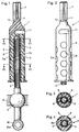
- the shift lever shown in Figure 1 is, as usual, in one here Motor vehicle, not shown, between the front seats in one here only indicated housing 13 stored.
- the storage takes place as usual with a joint ball 2, which is fixed to a rod-shaped Gear lever lower part 3 is attached.
- a further joint 10 is attached, with the transfer the movements of the shift lever 1 to the transmission become.
- a plastic sleeve 10a is otherwise made of metal manufactured shift lever lower part 3 used.
- the shift lever lower part 3 engages with a rod-shaped end 3a in a bell-shaped gear lever upper part 4.
- This end 3a can be provided with a plastic cap 9. To prevent rotation the cap 9, the end 3a can be knurled on the outside. An embodiment is also conceivable in which the cap 9 is on the end is snapped.
- the end 3a has not shown here Recesses on.
- the gear lever upper part 4 can be made of a hard plastic Injection molding processes are manufactured.
- a molded rod-shaped Shank 7 is used to attach a not shown here Knobs or knobs.
- this shaft 7 is preferably in cross section run out of round.
- the shaft 7 also has a circumferential one Groove 12 or rib on which this knob can be released is locked.
- This intermediate layer 5 consists of a thermoplastic elastomer or silicone with a hardness less than 50 Shore A.
- the hardness lies in the Range between 3 and 50 Shore A.
- the hardness is preferably the elastomer or silicone in the range from 3 to 30 Shore A, preferably 3 to 20 Shore A.
- the intermediate layer 5 is thus much softer than vulcanized rubber. It is also much softer than that from a comparatively hard Plastic-made gear lever upper part 4.
- Thermoplastic Elastomers with such hardness are known per se.
- the thermoplastic Elastomer can also be a mixture of elastomers or a silicone be.
- the intermediate layer 5 is preferably between the two parts 3 and 4 injected by injection molding. As can be seen is the space between these two parts 3 and 4 in essentially completely filled out. A cavity 11 at the top The end of part 3 can be provided. This cavity 11 is reduced the transmission of shocks and vibrations from Lower shift lever part 3 to the upper shift lever part 4.
- the shift lever upper part 4 has a bell-shaped wall 6 on that with several comparatively large and circular Breakthroughs 8 is provided.
- the intermediate layer 5 is as can be seen injected into these openings 8. On the one hand this creates a non-rotatable connection between the intermediate layer 5 and the gear lever upper part 4 reached. On the other hand is thereby a free surface 5a in the intermediate layer 5 created, which significantly improves vibration damping.
- the openings 8 form a kind of window through which the vibrations can radiate into the environment.
- the share of this free surfaces 5a is comparatively large and can for example be about 50% or more.
- connection of the intermediate layer 5 with the gear lever lower part 3 is carried out, for example, by plastic ribs 9, which according to Figure 4 are molded on the outside of the cap 9. Such or similar ribs can also be on the inside of the gear lever upper part 4 be attached. These preferably have plastic ribs 9a, not shown here, which the mechanical Improve anchorage.
- the anchoring of the intermediate layer 5 on the cap 9 can also by a chemical Connection. Is the cap 9 as mentioned above on the End 3a snapped, so the intermediate layer 5 before assembly of the lower part 3 between the cap 9 and the gear lever upper part 4 can be injected. This unit can then be retrofitted snapped onto the desired gear lever lower part 3 become. It is then possible to assemble the gear lever lower part during assembly 3 to mount without the upper gear lever part 4, whereby Space problems are avoidable.
Landscapes
- Engineering & Computer Science (AREA)
- Mechanical Engineering (AREA)
- General Engineering & Computer Science (AREA)
- Chemical & Material Sciences (AREA)
- Combustion & Propulsion (AREA)
- Transportation (AREA)
- Arrangement Or Mounting Of Control Devices For Change-Speed Gearing (AREA)
- Vibration Prevention Devices (AREA)
Abstract
Description
Die Erfindung betrifft einen Schalthebel für ein Kraftfahrzeug, mit einem Schalthebelunterteil, das mit einem Gelenk in der Karosserie des Kraftfahrzeuges gelagert ist, und mit einem Schalthebeloberteil sowie einer schwingungsdämmenden Zwischenschicht zwischen den genannten Schalthebelteilen.The invention relates to a gear lever for a motor vehicle, with a gear lever lower part with a joint in the body of the motor vehicle is mounted, and with a gear lever upper part as well as an anti-vibration intermediate layer between the mentioned gear lever parts.
Ein Schalthebel dieser Art ist im Stand der Technik aus der EP-A-0 570 661 bekannt geworden. Die schwingungsdämmende Zwischenschicht ist hier ein hülsenförmiger und vulkanisierter Gummikörper, der mit einem stabförmigen Schalthebelunterteil und einem glockenförmigen Schalthebeloberteil verklebt ist. Der Gummikörper hat die Aufgabe, die am Motor und am Kraftübertragungsstrang entstehenden Vibrationen und Schwingungen zu dämpfen. Der Gummikörper soll aber trotzdem eine präzise Übertragung von Betätigungsbewegungen für den Gangwechsel gewährleisten. Nachteilig ist bei diesem Schalthebel, dass dieser zum Vulkanisieren des Gummi körpers an ein dazu eingerichtetes Werk transportiert werden muss. Bei einem solchen Schalthebel liegt die Resonanzfrequenz bei etwa 200 Hz. Um die Resonanzfrequenz zu senken, ist ein geeichter Tilger erforderlich.A shift lever of this type is known from the prior art EP-A-0 570 661 has become known. The vibration-dampening intermediate layer here is a sleeve-shaped and vulcanized rubber body, the one with a rod-shaped gear lever lower part and a bell-shaped gear lever upper part is glued. The rubber body has the task on the engine and on the powertrain dampen vibrations and vibrations. Of the However, the rubber body is still intended to transmit actuation movements precisely ensure for the gear change. Disadvantageous is with this shift lever that this for vulcanizing the rubber body is transported to a factory set up for this purpose must become. With such a shift lever, the resonance frequency is at about 200 Hz. To lower the resonance frequency is a calibrated damper is required.
Die DE-A-2 022 723 offenbart einen Schalthebel, bei dem die Zwischenschicht aus ebenfalls vulkanisierten Gummiringen besteht. Auch bei diesem Schalthebel kann bei einem Kraftfahrzeug in der Regel nicht auf einen Tilger verzichtet werden, wenn eine für gehobene Ansprüche genügende Dämpfung erzielt werden soll. Ein Schalthebel mit einer Zwischenschicht aus vulkanisiertem Gummi wird ebenfalls in der JP-A-58 20 35 29 vorgeschlagen.DE-A-2 022 723 discloses a shift lever in which the intermediate layer consists of vulcanized rubber rings. This shift lever can also be used in a motor vehicle As a rule, an absorber should not be waived if one for high-quality damping should be achieved. A Shift lever with an intermediate layer of vulcanized rubber is also proposed in JP-A-58 20 35 29.
Der Erfindung liegt die Aufgabe zugrunde, einen Schalthebel der genannten Art zu schaffen, der sich durch eine bessere Dämpfung auszeichnet und der dennoch kostengünstig herstellbar ist und ein präzises Schalten ermöglicht.The invention has for its object a gear lever to create the kind mentioned, which is characterized by better damping distinguished and which is nevertheless inexpensive to manufacture and enables precise switching.
Die Aufgabe ist bei einem gattungsgemässen Schalthebel dadurch gelöst, dass die Zwischenschicht aus einem thermoplastischen Elastomer oder einem Silikon hergestellt ist. Im Gegensatz zu vulkanisiertem Gummi können thermoplastische Elastomere und Silikone mit einer Härte hergestellt werden, die wesentlich unter 50 Shore A liegt. Es hat sich gezeigt, dass mit einem thermoplastischen Elastomer oder Silikon als Zwischenschicht die Frequenz, verglichen mit einer Ausführung mit vulkanisiertem Gummi, um etwa 50 Hertz gesenkt werden kann. Damit kann in den meisten Fällen auf einen Tilger verzichtet werden. Ein präzises Schalten ist auch dann möglich, wenn die Härte wesentlich unterhalb von 50 Shore A liegt, beispielsweise im Bereich von 6 bis 20 Shore A.The task is in a generic shift lever solved that the intermediate layer from a thermoplastic Elastomer or a silicone is made. In contrast to Vulcanized rubber can be thermoplastic elastomers and silicones be made with a hardness that is significantly below 50 Shore A lies. It has been shown that with a thermoplastic Elastomer or silicone as an intermediate layer the frequency, compared to a version with vulcanized rubber, can be reduced by about 50 Hertz. This can be used in most In cases where an absorber is not required. A precise shift is also possible if the hardness is significantly below 50 Shore A is, for example, in the range from 6 to 20 Shore A.
Ein wesentlicher Vorteil der Erfindung wird auch darin gesehen, dass der Schalthebel nicht wie bisher üblich für die Vulkanisation an ein dafür eingerichtetes Werk tranportiert werden muss, da das thermoplastische Elastomer oder das Silikon in einfacher Weise durch Spritzguss zwischen die Schalthebelteile eingebracht werden kann. Geeignete Spritzgussvorrichtungen können in jedem Werk installiert werden. Lange Transportwege für die Vulkanisation sind damit hinfällig. Die Herstellung des erfindungsgemässen Schalthebels ist somit wesentlich einfacher und kostengünstiger als beim Stand der Technik. An essential advantage of the invention is also seen in that the gear lever is not as usual for vulcanization must be transported to a plant set up for this purpose, because the thermoplastic elastomer or the silicone in simpler Introduced by injection molding between the shift lever parts can be. Suitable injection molding devices can be used in any Factory installed. Long transport routes for vulcanization are therefore obsolete. The production of the Shift lever is thus much easier and cheaper than in the prior art.
Ein Vorteil der Erfindung wird auch darin gesehen, dass thermoplastische Elastomere oder Silikone in vielen unterschiedlichen Mischungen und damit mit unterschiedlichen Dämpfungseigenschaften hergestellt und gespritzt werden können. Die Dämpfungseigenschaften können damit optimal an die Anwendung angepasst werden.An advantage of the invention is also seen in the fact that thermoplastic Elastomers or silicones in many different ways Mixtures and thus with different damping properties can be produced and injected. The damping properties can be optimally adapted to the application.
Die Herstellung des erfindungsgemässen Schalthebels ist dann besonders kostengünstig, wenn nach einer Weiterbildung der Erfindung das Schalthebeloberteil aus Kunststoff im Spritzgussverfahren hergestellt ist. Die Herstellung des Schalthebeloberteils aus Kunststoff im Spritzgussverfahren hat auch den weiteren Vorteil, dass, verglichen mit einem Teil aus Metall, wesentlich mehr Möglichkeiten in Bezug auf die Formgebung dieses Teils bestehen.The manufacture of the shift lever according to the invention is then special inexpensive if after a further development of the invention the gear lever upper part made of plastic by injection molding is made. The manufacture of the gear lever upper part made of plastic by injection molding also has the further advantage that, compared to a part made of metal, essential There are more options in terms of the shape of this part.
Gemäss einer Weiterbildung der Erfindung weist das Schalthebeloberteil in einer glockenförmigen Wandung mehrere Durchbrüche auf. Das thermoplastische Elastomer oder das Silikon ist in diese Durchbrüche eingespritzt. Damit ist erreicht, dass das thermoplastische Elastomer am Umfang des Schalthebels eine freie Oberfläche besitzt, an welcher Vibrationen an die Umgebung abgegeben werden können. Solche Durchbrüche können dann besonders einfach hergestellt werden, wenn das Schalthebeloberteil wie oben vorgeschlagen aus einem geeigneten Kunststoff im Spritzgussverfahren hergestellt ist. Der Anteil dieser freien Oberfläche kann wesentlich sein und beispielsweise 50% oder mehr der Oberfläche des Schalthebeloberteils betragen. Diese Durchbrüche dienen auch dazu, das obere Schalthebeloberteil drehfest mit dem thermoplastischen Elastomer oder Silikon zu verbinden.According to a development of the invention, the gear lever upper part several openings in a bell-shaped wall on. The thermoplastic elastomer or silicone is in this Breakthroughs injected. This means that thermoplastic elastomer on the circumference of the shift lever a free Has surface on which vibrations are released to the environment can be. Such breakthroughs can then be special easy to manufacture if the gear lever upper part like Proposed above from a suitable plastic by injection molding is made. The proportion of this free surface can be essential and for example 50% or more of the Surface of the gear lever upper part. These breakthroughs also serve to rotate the upper gear lever upper part with the to connect thermoplastic elastomer or silicone.
Ein Ausführungsbeispiel der Erfindung wird nachfolgend anhand
der Zeichnung näher erläutert. Es zeigen:
Der in Figur 1 gezeigte Schalthebel ist wie üblich in einem hier
nicht gezeigten Kraftfahrzeug zwischen den Vordersitzen in einem
hier nur angedeuteten Gehäuse 13 gelagert. Die Lagerung erfolgt
wie üblich mit einer Gelenkkugel 2, die fest an einem stabförmigen
Schalthebelunterteil 3 angebracht ist. Am unteren Ende des
Schalthebels 1 ist ein weiteres Gelenk 10 angebracht, mit dem
die Bewegungen des Schalthebels 1 auf das Getriebe übertragen
werden. Eine Kunststoffhülse 10a ist in das ansonsten aus Metall
hergestellte Schalthebelunterteil 3 eingesetzt.The shift lever shown in Figure 1 is, as usual, in one here
Motor vehicle, not shown, between the front seats in one
here only indicated
Mit einem stabförmigen Ende 3a greift das Schalthebelunterteil 3
in ein glockenförmigen Schalthebeloberteil 4 ein. Dieses Ende 3a
kann mit einer Kunststoffkappe 9 versehen sein. Zur Drehsicherung
der Kappe 9 kann das Ende 3a aussenseitig gerändelt sein.
Denkbar ist auch eine Ausführung, bei welcher die Kappe 9 auf
das Ende aufgerastet ist. Das Ende 3a weist dazu hier nicht gezeigte
Ausnehmungen auf.The shift lever
Das Schalthebeloberteil 4 kann aus einem harten Kunststoff im
Spritzgussverfahren hergestellt werden. Ein angeformter stabförmiger
Schaft 7 dient zur Befestigung eines hier nicht gezeigten
Knaufs oder Knopfs. Dazu ist dieser Schaft 7 im Querschnitt vorzugsweise
unrund ausgeführt. Weiter weist der Schaft 7 eine umlaufende
Rille 12 oder Rippe auf, an welcher dieser Knauf lösbar
verrastet ist. The gear lever
Zwischen dem Schalthebelunterteil 3 und dem Schalthebeloberteil
4 befindet sich eine Zwischenschicht 5, die den im wesentlichen
zylindrischen Zwischenraum zwischen diesen beiden Teilen
3 und 4 im wesentlichen vollständig ausfüllt. Diese Zwischenschicht
5 besteht aus einem thermoplastischen Elastomer oder Silikon
mit einer Härte kleiner als 50 Shore A. Die Härte liegt im
Bereich zwischen 3 und 50 Shore A. Vorzugsweise liegt die Härte
des Elastomers oder Silikon im Bereich von 3 bis 30 Shore A,
vorzugsweise 3 bis 20 Shore A. Die Zwischenschicht 5 ist somit
wesentlich weicher als vulkanisierter Gummi. Sie ist ebenfalls
wesentlich weicher als das aus einem vergleichsweise harten
Kunststoff hergestellte Schalthebeloberteil 4. Thermoplastische
Elastomere mit solchen Härten sind an sich bekannt. Das thermoplastische
Elastomer kann auch ein Elastomergemisch oder ein Silikon
sein.Between the gear lever
Die Zwischenschicht 5 ist vorzugsweise zwischen die beiden Teile
3 und 4 im Spritzgussverfahren eingespritzt. Wie ersichtlich,
ist der Zwischenraum zwischen diesen beiden Teilen 3 und 4 im
wesentlichen vollständig ausgefüllt. Ein Hohlraum 11 am oberen
Ende des Teils 3 kann vorgesehen sein. Dieser Hohlraum 11 vermindert
die Weiterleitung von Stössen und Vibrationen vom
Schalthebelunterteil 3 an das Schalthebeloberteil 4.The
Das Schalthebeloberteil 4 weist eine glockenförmige Wandung 6
auf, die mit mehreren vergleichsweise grossen und kreisrunden
Durchbrüchen 8 versehen ist. Die Zwischenschicht 5 ist wie ersichtlich
in diese Durchbrüche 8 hineingespritzt. Einerseits
wird dadurch eine drehfeste Verbindung zwischen der Zwischenschicht
5 und dem Schalthebeloberteil 4 erreicht. Andererseits
wird dadurch in der Zwischenschicht 5 eine freie Oberfläche 5a
geschaffen, welche die Vibrationsdämpfung wesentlich verbessert.
Die Durchbrüche 8 bilden eine Art Fenster, durch welche die Vibrationen
in die Umgebung abstrahlen können. Der Anteil dieser
freien Oberflächen 5a ist vergleichsweise gross und kann beispielsweise
etwa 50% oder mehr betragen.The shift lever
Die Verbindung der Zwischenschicht 5 mit dem Schalthebelunterteil
3 erfolgt beispielsweise durch Kunststoffrippen 9, die gemäss
Figur 4 an der Kappe 9 aussenseitig angeformt sind. Solche
oder ähnliche Rippen können auch innenseitig am Schalthebeloberteil
4 angebracht sein. Vorzugsweise weisen diese Kunststoffrippen
9a hier nicht gezeigte Durchbrüche auf, welche die mechanische
Verankerung verbessern. Die Verankerung der Zwischenschicht
5 an der Kappe 9 kann aber auch durch eine chemische
Verbindung erfolgen. Ist die Kappe 9 wie oben erwähnt auf das
Ende 3a aufgerastet, so kann die Zwischenschicht 5 vor der Montage
des Unterteils 3 zwischen die Kappe 9 und den Schalthebeloberteil
4 eingespritzt werden. Diese Einheit kann dann nachträglich
auf den gewünschten Schalthebelunterteil 3 aufgerastet
werden. Bei der Montage ist es dann möglich, den Schalthebelunterteil
3 ohne Schalthebeloberteil 4 zu montieren, wodurch
Platzprobleme vermeidbar sind.The connection of the
Claims (12)
Applications Claiming Priority (2)
| Application Number | Priority Date | Filing Date | Title |
|---|---|---|---|
| CH30498 | 1998-02-05 | ||
| CH30498 | 1998-02-05 |
Publications (2)
| Publication Number | Publication Date |
|---|---|
| EP0935084A2 true EP0935084A2 (en) | 1999-08-11 |
| EP0935084A3 EP0935084A3 (en) | 2000-02-23 |
Family
ID=4183957
Family Applications (1)
| Application Number | Title | Priority Date | Filing Date |
|---|---|---|---|
| EP99810013A Withdrawn EP0935084A3 (en) | 1998-02-05 | 1999-01-11 | Gear shift lever for a motor vehicle |
Country Status (1)
| Country | Link |
|---|---|
| EP (1) | EP0935084A3 (en) |
Cited By (3)
| Publication number | Priority date | Publication date | Assignee | Title |
|---|---|---|---|---|
| DE102007029049B4 (en) * | 2006-07-04 | 2009-07-23 | Eissmann Automotive Deutschland Gmbh | Handle a shift rod |
| CN112833175A (en) * | 2021-02-26 | 2021-05-25 | 南京奥联汽车电子电器股份有限公司 | A soft-covered shift lever for electronic shifter |
| US20240240712A1 (en) * | 2023-01-13 | 2024-07-18 | Lund, Inc. | Shifter lever |
Citations (3)
| Publication number | Priority date | Publication date | Assignee | Title |
|---|---|---|---|---|
| DE2022723A1 (en) | 1970-05-09 | 1971-11-25 | Phoenix Gummiwerke Ag | Connecting element for linkage between gear and shift lever |
| JPS58203529A (en) | 1982-05-21 | 1983-11-28 | Kinugawa Rubber Ind Co Ltd | Shifting lever of gear |
| EP0570661A1 (en) | 1992-05-20 | 1993-11-24 | Firma Carl Freudenberg | Gearshift lever |
Family Cites Families (5)
| Publication number | Priority date | Publication date | Assignee | Title |
|---|---|---|---|---|
| DE7002581U (en) * | 1970-01-27 | 1970-07-16 | Opel Adam Ag | GEAR SHIFT LEVER FOR VEHICLE TRANSMISSION. |
| IT8153070U1 (en) * | 1981-04-01 | 1982-10-01 | Lear Snc | PREFORMED FULL COVERING SPECIFICALLY FOR CAR GEAR CHANGE CONTROL LEVERS, INCORPORATING THE HANDLE KNOB AND THE PROTECTIVE BELLOWS FOR THE LEVER JOINT. |
| JPH04342820A (en) * | 1991-05-17 | 1992-11-30 | Tokai Rubber Ind Ltd | Flexible joint for exhaust pipe in vehicle |
| US5467664A (en) * | 1993-07-26 | 1995-11-21 | Black River Manufacturing, Inc. | Noise abating vehicle transmission shift lever |
| FR2756227B1 (en) * | 1996-11-22 | 1998-12-31 | Peugeot | MANEUVER LEVER PROVIDED WITH A FILTERING DEVICE, AND METHOD FOR MANUFACTURING SUCH A LEVER |
-
1999
- 1999-01-11 EP EP99810013A patent/EP0935084A3/en not_active Withdrawn
Patent Citations (3)
| Publication number | Priority date | Publication date | Assignee | Title |
|---|---|---|---|---|
| DE2022723A1 (en) | 1970-05-09 | 1971-11-25 | Phoenix Gummiwerke Ag | Connecting element for linkage between gear and shift lever |
| JPS58203529A (en) | 1982-05-21 | 1983-11-28 | Kinugawa Rubber Ind Co Ltd | Shifting lever of gear |
| EP0570661A1 (en) | 1992-05-20 | 1993-11-24 | Firma Carl Freudenberg | Gearshift lever |
Cited By (4)
| Publication number | Priority date | Publication date | Assignee | Title |
|---|---|---|---|---|
| DE102007029049B4 (en) * | 2006-07-04 | 2009-07-23 | Eissmann Automotive Deutschland Gmbh | Handle a shift rod |
| CN112833175A (en) * | 2021-02-26 | 2021-05-25 | 南京奥联汽车电子电器股份有限公司 | A soft-covered shift lever for electronic shifter |
| US20240240712A1 (en) * | 2023-01-13 | 2024-07-18 | Lund, Inc. | Shifter lever |
| US12066097B2 (en) * | 2023-01-13 | 2024-08-20 | Lund, Inc. | Shifter lever |
Also Published As
| Publication number | Publication date |
|---|---|
| EP0935084A3 (en) | 2000-02-23 |
Similar Documents
| Publication | Publication Date | Title |
|---|---|---|
| DE3635278A1 (en) | SHIFT LEVER DEVICE | |
| EP0902198A2 (en) | Plug connector | |
| DE2838520A1 (en) | VEHICLE REAR VIEW MIRROR | |
| DE4026652C2 (en) | ||
| EP1611367A1 (en) | Hydraulically damping rubber bush bearing for vertical mounting | |
| DE3305422C1 (en) | Ball bushing for the gearshift lever of a motor vehicle | |
| DE19736106B4 (en) | Storage of a shift lever for an external circuit of a motor vehicle transmission | |
| WO2015058763A1 (en) | Shift device | |
| DE3730582A1 (en) | BEARING FOR THE ELASTIC, VIBRATION-DAMPING STORAGE OF COMPONENTS | |
| WO2011072666A1 (en) | Hydraulically damping engine mount | |
| EP0935084A2 (en) | Gear shift lever for a motor vehicle | |
| EP1503096A2 (en) | Retaining member for securing at least one bearing | |
| EP2569557B1 (en) | Device for transmitting a shift movement | |
| DE4141986A1 (en) | Car gearbox gearchange linkage latch - has ball retaining element in plastics housing with metal bush moulded into it | |
| DE19948422A1 (en) | Selector unit especially for gearbox in motor vehicle has cover fabricated in one piece from sheet metal in forming process and with stop contour which interacts with stop element on transmission shaft | |
| DE19755284A1 (en) | Ball and socket joint for e.g. gear shift linkage | |
| DE10149519C1 (en) | buffer assembly | |
| DE20101876U1 (en) | Elastic bumper, in particular for a rear flap of a motor vehicle | |
| DE8235995U1 (en) | Resilient support for a shock absorber of a front suspension of a vehicle | |
| DE102011117087A1 (en) | Decoupling element and arrangement for vibration-decoupling attachment of a functional module to a vehicle part and method for producing such | |
| DE19905308B4 (en) | Switching device, shift lever and shift lever guide, in particular for a motor vehicle transmission | |
| DE2922543A1 (en) | SUPPORT CLAMP | |
| DE4025446C2 (en) | ||
| DE4326937C2 (en) | Bowden cable-like clutch cable | |
| DE4103931A1 (en) | STABILIZING AND SUPPORTING DEVICE FOR THE SWIVEL BEARING OF A CLUTCH LEVER |
Legal Events
| Date | Code | Title | Description |
|---|---|---|---|
| PUAI | Public reference made under article 153(3) epc to a published international application that has entered the european phase |
Free format text: ORIGINAL CODE: 0009012 |
|
| AK | Designated contracting states |
Kind code of ref document: A2 Designated state(s): CH DE ES FR IT LI |
|
| AX | Request for extension of the european patent |
Free format text: AL;LT;LV;MK;RO;SI |
|
| PUAL | Search report despatched |
Free format text: ORIGINAL CODE: 0009013 |
|
| AK | Designated contracting states |
Kind code of ref document: A3 Designated state(s): AT BE CH CY DE DK ES FI FR GB GR IE IT LI LU MC NL PT SE |
|
| AX | Request for extension of the european patent |
Free format text: AL;LT;LV;MK;RO;SI |
|
| 17P | Request for examination filed |
Effective date: 20000814 |
|
| AKX | Designation fees paid |
Free format text: CH DE ES FR IT LI |
|
| 17Q | First examination report despatched |
Effective date: 20010928 |
|
| STAA | Information on the status of an ep patent application or granted ep patent |
Free format text: STATUS: THE APPLICATION IS DEEMED TO BE WITHDRAWN |
|
| 18D | Application deemed to be withdrawn |
Effective date: 20020209 |