EP0934839B1 - Independent suspension for non-steered wheels of motor vehicles - Google Patents
Independent suspension for non-steered wheels of motor vehicles Download PDFInfo
- Publication number
- EP0934839B1 EP0934839B1 EP19990102240 EP99102240A EP0934839B1 EP 0934839 B1 EP0934839 B1 EP 0934839B1 EP 19990102240 EP19990102240 EP 19990102240 EP 99102240 A EP99102240 A EP 99102240A EP 0934839 B1 EP0934839 B1 EP 0934839B1
- Authority
- EP
- European Patent Office
- Prior art keywords
- shock absorber
- spring
- independent suspension
- vehicle
- aperture
- Prior art date
- Legal status (The legal status is an assumption and is not a legal conclusion. Google has not performed a legal analysis and makes no representation as to the accuracy of the status listed.)
- Expired - Lifetime
Links
Images
Classifications
-
- B—PERFORMING OPERATIONS; TRANSPORTING
- B60—VEHICLES IN GENERAL
- B60G—VEHICLE SUSPENSION ARRANGEMENTS
- B60G15/00—Resilient suspensions characterised by arrangement, location or type of combined spring and vibration damper, e.g. telescopic type
- B60G15/02—Resilient suspensions characterised by arrangement, location or type of combined spring and vibration damper, e.g. telescopic type having mechanical spring
- B60G15/06—Resilient suspensions characterised by arrangement, location or type of combined spring and vibration damper, e.g. telescopic type having mechanical spring and fluid damper
- B60G15/062—Resilient suspensions characterised by arrangement, location or type of combined spring and vibration damper, e.g. telescopic type having mechanical spring and fluid damper the spring being arranged around the damper
-
- B—PERFORMING OPERATIONS; TRANSPORTING
- B60—VEHICLES IN GENERAL
- B60G—VEHICLE SUSPENSION ARRANGEMENTS
- B60G3/00—Resilient suspensions for a single wheel
- B60G3/18—Resilient suspensions for a single wheel with two or more pivoted arms, e.g. parallelogram
- B60G3/20—Resilient suspensions for a single wheel with two or more pivoted arms, e.g. parallelogram all arms being rigid
- B60G3/202—Resilient suspensions for a single wheel with two or more pivoted arms, e.g. parallelogram all arms being rigid having one longitudinal arm and two parallel transversal arms, e.g. dual-link type strut suspension
Definitions
- the invention relates to an independent suspension for non-steered wheels of motor vehicles, in particular of passenger cars, according to the preamble of claim 1.
- the object of the invention is to provide an independent suspension for non-steered wheels of motor vehicles, which requires relatively little space with a high ride comfort.
- the lower end of the shock absorber is arranged in the vehicle longitudinal direction to the front end of the motor vehicle in front of the wheel center and in front of a drive shaft by the shock absorber is passed through an opening formed in the upper arm and the spring.
- the installation length of the shock absorber is significantly shorter at the same Radhub as in the above-described known independent suspension, so that a projecting into the trunk damper dome is lower and thus advantageously increases the through-loading width and the trunk volume of the motor vehicle provided with the independent suspension according to the invention.
- the ratio i of the shock absorber i about 0.7.
- the through-loading width of a boot then increases depending on the embodiment of the body structure by about 10%.
- the increase in the trunk volume when using the independent suspension according to the invention is about 5%.
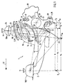
- Fig. 1 shows an independent suspension 1 for not shown, not steered wheels of a motor vehicle.
- the independent suspension 1 has a trailing arm 2, an upper and a lower arm 3 and 4.
- an apparent in Figs. 2 and 3 opening 5 is formed, through which a shock absorber 6 is passed.
- a spring 7 is disposed between a sheet metal pot 34 or the like and the upper arm 3.
- the sheet metal pot 34 is attached to a body 11.
- the independent suspension 1 is true to the change in the arrangement of the shock absorber 6 with the described in ATZ 93 (1991), pages 274 to 280 "central handlebar rear axle” match. To avoid repetition, reference is made to the features described therein.
- the trailing arm 2 is connected with its one end 9 elastically via a bearing 10 on the body 11.
- the opposite end 12 of the trailing arm 2 is formed as a wheel carrier 13.
- the superimposed wishbones 3 and 4 are articulated elastically with their respective one end 14, 15 on a subframe 16 not shown in detail via rubber bearings.
- the opposite ends 17, 18 of the control arm 3, 4 are connected via joints 19, 20 with the wheel carrier 13.
- the upper end 8 of the shock absorber 6 is disposed within the sheet metal pot 34 and connected via an elastic bearing 21, in particular a rubber bearing, with the sheet metal pot 34.
- a lower end 22 of the shock absorber 6 is hinged to the trailing arm 2 so that the lower end 22 is displaced towards the front in the vehicle longitudinal direction 32 in comparison to the upper end 8 of the shock absorber 6 and the shock absorber 6 has a corresponding inclination.
- the spring 7 is supported by its upper end 23 on the sheet metal pot 34.
- a lower end 24 of the spring 7 is disposed on the upper arm 3.
- F L is a force to be absorbed by the bearing 11.
- F Se and F Sa are each a force acting on the lower end 22 of the shock absorber 6 in the rebounded or rebounded state 28, 29.
- F R denotes a supported in the Radmitte 33 by the wheel carrier 13 force.
- the spring 7 is designed as a conical spring due to the space required by the shock absorber 6 during spring deflection.
- Fig. 1 is further a through hole 25 in height of a wheel center 33 in the wheel carrier 13 for a drive shaft 27 shown in FIGS. 2 and 3 can be seen.
- Fig. 1 the position of the caliper 26 can be seen.
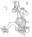
- the surface of the upper transverse link 3 widened to support the lower end 24 of the spring 7 can be seen.
- the formed in the upper arm 3 opening 5 is elongated according to the space required by the shock absorber 6 during the passage, as shown in part by the dotted line in Fig. 2.
- the position of the shock absorber 6 in the rebounded position 28 and in the rebounded position 29 is illustrated by a respective center line 30e and 30a of the shock absorber 6 and a double arrow 31.
Description
Die Erfindung betrifft eine Einzelradaufhängung für nichtgelenkte Räder von Kraftfahrzeugen, insbesondere von Personenkraftwagen, gemäß dem Oberbegriff des Anspruchs 1.The invention relates to an independent suspension for non-steered wheels of motor vehicles, in particular of passenger cars, according to the preamble of
Aus der ATZ 93 (1991), Seiten 274 bis 280 ist bereits eine gattungsbildende Einzelradaufhängung für nichtgelenkte Räder von Kraftfahrzeugen bekannt. Bei dieser Einzelradaufhängung sind zwei übereinander angeordnete Querlenker jeweils mit ihrem einen Ende an einem Radträger angelenkt. Die aufbauseitigen Enden der Querlenker sind in Fahrzeuglängsrichtung nach vome, d. h. zum vorderen Ende des Kraftfahrzeuges, gerichtet und gelenkig an einem Fahrzeugaufbau oder einem Fahrschemel oder dergleichen angeordnet. Ein Ende eines Längslenkers ist als ein Radträger ausgebildet. Das dazu gegenüberliegende Ende des Längslenkers ist über ein elastisches Lager am Fahrzeugaufbau oder dergleichen angelenkt. Auf dem oberen Querlenker stützt sich ein unteres Ende einer Feder ab. Der Stoßdämpfer ist hinter der Radmitte und hinter einer Antriebswelle in Richtung Fahrzeugheck angeordnet. Dadurch ergibt sich eine Übersetzung i des Stoßdämpfers zu i > 1, dies ist zwar hinsichtlich des Ansprechverhaltens des Stoßdämpfers vorteilhaft, eine solche Übersetzung wirkt sich aber negativ auf die Baulänge des Stoßdämpfers aus. Daher benötigt der Stoßdämpfer relativ viel Bauraum, so daß insbesondere die Kofferraumgröße durch jeweils einen entsprechend groß bauenden Dämpferdom verringert sein kann.From ATZ 93 (1991), pages 274 to 280, a generic independent suspension for non-steered wheels of motor vehicles is already known. In this independent suspension two superimposed wishbones are articulated in each case with its one end to a wheel carrier. The body-side ends of the control arms are in the vehicle longitudinal direction to vome, ie the front end of the motor vehicle, directed and hinged to a vehicle body or a subframe or the like. One end of a trailing arm is formed as a wheel carrier. The opposite end of the trailing arm is articulated via an elastic bearing on the vehicle body or the like. On the upper wishbone, a lower end of a spring is supported. The shock absorber is located behind the wheel center and behind a drive shaft in the direction of the vehicle rear. This results in a ratio i of the shock absorber to i> 1, this is indeed advantageous in terms of the response of the shock absorber, but such a translation has a negative effect on the length of the shock absorber. Therefore, the shock absorber requires a relatively large amount of space, so that in particular the trunk size can be reduced by a correspondingly large-sized damper dome.
Aufgabe der Erfindung ist es, eine Einzelradaufhängung für nichtgelenkte Räder von Kraftfahrzeugen zu schaffen, die bei einem hohen Fahrkomfort relativ wenig Bauraum erfordert.The object of the invention is to provide an independent suspension for non-steered wheels of motor vehicles, which requires relatively little space with a high ride comfort.
Diese Aufgabe wird durch die Merkmale des Anspruchs 1 gelöst.This object is solved by the features of
Bei der erfindungsgemäßen Einzelradaufhängung ist das untere Ende des Stoßdämpfers in Fahrzeuglängsrichtung zum vorderen Ende des Kraftfahrzeuges hin vor der Radmitte und vor einer Antriebswelle angeordnet, indem der Stoßdämpfer durch eine im oberen Querlenker ausgebildete Öffnung und durch die Feder hindurchgeführt ist. Dadurch ergibt sich eine Änderung der Übersetzung i des Stoßdämpfers in der Weise, daß i < 1 wird. Durch diese Übersetzungsänderung wird bei gleichem Radhub wie bei der oben beschriebenen, bekannten Einzelradaufhängung die Einbaulänge des Stoßdämpfers deutlich kürzer, so daß ein in den Kofferraum ragender Dämpferdom niedriger ist und sich somit vorteilhafterweise die Durchladebreite und das Kofferraumvolumen des mit der erfindungsgemäßen Einzelradaufhängung versehenen Kraftfahrzeuges erhöht.In the independent suspension according to the invention, the lower end of the shock absorber is arranged in the vehicle longitudinal direction to the front end of the motor vehicle in front of the wheel center and in front of a drive shaft by the shock absorber is passed through an opening formed in the upper arm and the spring. This results in a change in the ratio i of the shock absorber in such a way that i <1. By this ratio change the installation length of the shock absorber is significantly shorter at the same Radhub as in the above-described known independent suspension, so that a projecting into the trunk damper dome is lower and thus advantageously increases the through-loading width and the trunk volume of the motor vehicle provided with the independent suspension according to the invention.
In einer vorteilhaften Ausführungsform beträgt die Übersetzung i des Stoßdämpfers i = ca. 0,7. Die Durchladebreite eines Kofferraumes erhöht sich dann je nach Ausführungsform der Karosseriestruktur um ca. 10%. Die Vergrößerung des Kofferraumvolumens bei der Verwendung der erfindungsgemäßen Einzelradaufhängung liegt bei ca. 5%.In an advantageous embodiment, the ratio i of the shock absorber i = about 0.7. The through-loading width of a boot then increases depending on the embodiment of the body structure by about 10%. The increase in the trunk volume when using the independent suspension according to the invention is about 5%.
Eine Ausführungsform der Erfindung wird nachstehend anhand der Zeichnungen beispielshalber beschrieben. Dabei zeigen:
- Fig. 1
- eine Ansicht von der Seite einer Einzelradaufhängung,
- Fig. 2
- eine Ansicht von oben der in der Fig. 1 dargestellten Einzelradaufhängung und
- Fig. 3
- eine Ansicht von hinten der in den Fig. 1 und 2 dargestellten Einzelradaufhängung.
- Fig. 1
- a view from the side of an independent suspension,
- Fig. 2
- a top view of the illustrated in Fig. 1 independent suspension and
- Fig. 3
- a view from the rear of the independent suspension shown in FIGS. 1 and 2.
Die Fig. 1 zeigt eine Einzelradaufhängung 1 für nicht dargestellte, nicht gelenkte Räder eines Kraftfahrzeuges. Die Einzelradaufhängung 1 weist einen Längslenker 2, einen oberen und einen unteren Querlenker 3 und 4 auf. In dem oberen Querlenker 3 ist eine in den Fig. 2 und 3 ersichtliche Öffnung 5 ausgebildet, durch die ein Stoßdämpfer 6 hindurchgeführt ist. Eine Feder 7 ist zwischen einem Blechtopf 34 oder dergleichen und dem oberen Querlenker 3 angeordnet. Der Blechtopf 34 ist an einer Karosserie 11 befestigt.Fig. 1 shows an
Die Einzelradaufhängung 1 stimmt bis auf die Veränderung der Anordnung des Stoßdämpfers 6 mit der in der ATZ 93 (1991), Seiten 274 bis 280 beschriebenen "Zentral-Lenker-Hinterachse" überein. Zur Vermeidung von Wiederholungen wird auf die dort beschriebenen Merkmale verwiesen.The
Der Längslenker 2 ist mit seinem einen Ende 9 elastisch über ein Lager 10 an der Karosserie 11 angebunden. Das dazu gegenüberliegende Ende 12 des Längslenkers 2 ist als ein Radträger 13 ausgebildet. Die übereinander angeordneten Querlenker 3 und 4 sind mit ihrem jeweiligen einen Ende 14, 15 an einem nicht näher dargestellten Fahrschemel 16 über Gummilager elastisch angelenkt. Die dazu gegenüberliegenden Enden 17, 18 der Querlenker 3, 4 sind über Gelenke 19, 20 mit dem Radträger 13 verbunden. Das obere Ende 8 des Stoßdämpfers 6 ist innerhalb des Blechtopfes 34 angeordnet und über ein elastisches Lager 21, insbesondere ein Gummilager, mit dem Blechtopf 34 verbunden. Ein unteres Ende 22 des Stoßdämpfers 6 ist am Längslenker 2 so angelenkt, daß das untere Ende 22 im Vergleich zum oberen Ende 8 des Stoßdämpfers 6 nach vorne in Fahrzeuglängsrichtung 32 verschoben ist und der Stoßdämpfer 6 eine entsprechende Neigung aufweist. Die Feder 7 stützt sich mit ihrem oberen Ende 23 an dem Blechtopf 34 ab. Ein unteres Ende 24 der Feder 7 ist auf dem oberen Querlenker 3 angeordnet.The trailing arm 2 is connected with its one end 9 elastically via a
In der Fig. 1 sind ferner einzelne, in vertikaler Richtung wirkende Kräfte FL, FSe, FSa und FR sowie einzelne Abstände bzw. Hebelarme ae, aa, b, ce und ca zwischen den genannten Kräften eingetragen. Die Fußnoten e oder a betreffen jeweils den eingefederten oder ausgefederten Zustand 28, 29 des unteren Endes 22 des Stoßdämpfers 6. Entsprechend ist die Mittellinie 30 des Stoßdämpfers 6 mit den Fußnoten e und a versehen. In der Fig. 1 zeigt der in durchgezogenen Linien dargestellte Stoßdämpfer 6 und die ohne Fußnote versehene Mittellinie 30 eine Einfederungslage der Radaufhängung 1, die zwischen dem vollständig eingefederten und ausgefederten Zustand liegt.In FIG. 1, individual forces F L , F Se , F Sa and F R acting in the vertical direction as well as individual distances or lever arms a e , a a , b, c e and c a are also plotted between said forces. The footnotes e or a respectively relate to the sprung or rebounded
FL ist eine durch das Lager 11 aufzunehmende Kraft. FSe und FSa ist jeweils eine auf das untere Ende 22 des Stoßdämpfers 6 im eingefederten bzw. ausgefederten Zustand 28, 29 wirkende Kraft. FR bezeichnet eine in der Radmitte 33 durch den Radträger 13 abgestützte Kraft.F L is a force to be absorbed by the
Zwischen dem Längslenker-Lager 10 und der Radmitte 33 besteht ein vom Einfederungszustand der Radaufhängung 1 abhängiger Abstand b. Ein Abstand a zwischen dem unteren Ende 22 des Stoßdämpfers 6 schwankt zwischen einem Abstand ae im eingefederten Zustand 28 des Stoßdämpfers 6 und einem Abstand aa im ausgefederten Zustand 29 des Stoßdämpfers 6. Entsprechend schwankt ein Abstand c zwischen den beiden Kräften FR und FSe sowie FSa, der sich aus der Differenz c = b - a ergibt, zwischen einem Wert ce und ca.Between the trailing arm bearing 10 and the
Für den eingefederten Zustand 28 des Stoßdämpfers 6 ergibt sich durch die Verlagerung des Stoßdämpfers 6 in Richtung zu einem nicht dargestellten vorderen Ende des Kraftfahrzeuges näherungsweise eine Übersetzung i = ae/b < 1.For the compressed
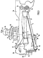
Wie insbesondere aus den Fig. 1 und 3 hervorgeht, ist die Feder 7 aufgrund des Raumbedarfs des Stoßdämpfers 6 beim Durchfedern als Kegelfeder ausgelegt. Aus der Fig. 1 ist ferner eine Durchgangsöffnung 25 in Höhe einer Radmitte 33 im Radträger 13 für eine in den Fig. 2 und 3 dargestellte Antriebswelle 27 erkennbar. Zusätzlich ist in der Fig. 1 die Lage des Bremssattels 26 ersichtlich.As is apparent in particular from FIGS. 1 and 3, the
Aus der Draufsicht der Fig. 2 ist die zur Abstützung des unteren Endes 24 der Feder 7 verbreiterte Oberfläche des oberen Querlenkers 3 erkennbar. Die in dem oberen Querlenker 3 ausgebildete Öffnung 5 ist entsprechend dem Raumbedarf des Stoßdämpfers 6 beim Durchfedem länglich ausgebildet, wie dies zum Teil durch die punktierte Linie in der Fig. 2 gezeigt ist. In der Fig. 2 ist die Lage des Stoßdämpfers 6 in der eingefederten Stellung 28 und in der ausgefederten Stellung 29 anhand jeweils einer Mittellinie 30e und 30a des Stoßdämpfers 6 und eines Doppelpfeiles 31 dargestellt.2, the surface of the upper transverse link 3 widened to support the
Aus der Fig. 3 ist die Anordnung der Querlenker 3 und 4 übereinander ersichtlich. In punktierten Linien ist die Quererstreckung des Längslenkers 2 gezeigt. Ferner geht aus der Fig. 3 hervor, daß der Stoßdämpfer 6 relativ kurz baut. Die Radaufhängung 1 befindet sich in einem Einfederungszustand, der zwischen dem vollständig eingefederten und ausgefederten Zustand liegt.From Fig. 3, the arrangement of the control arm 3 and 4 can be seen one above the other. In dotted lines, the transverse extent of the trailing arm 2 is shown. Furthermore, it is apparent from Fig. 3 that the
Claims (4)
- An independent wheel suspension for non-steered wheels of a motor vehicle, comprising a wheelmount (13), on which two transverse links (3, 4) arranged one above the other are articulated, the ends (14, 15) of which on the body side are directed to the front in the longitudinal direction of the vehicle and which are arranged, in each case, on a vehicle body or a suspension subframe (16) via a joint (19, 20), comprising a longitudinal link (2), in which the one end (12) is configured as a wheelmount (13) and the other end (9) is articulated to the vehicle body or the like via an elastic bearing (10), wherein a lower end (24) of a spring (7) is supported on the upper transverse link (3), and comprising a shock absorber (6),
characterised in that the upper transverse link (3) has a through-aperture (5), in that the shock absorber (6) is guided through the spring (7) and the through-aperture (5) of the upper transverse link (3), the lower end (22) of said shock absorber being articulated in the longitudinal direction (32) of the vehicle between a wheel centre (33) and the end (9) on the body side of the longitudinal link (2), and in that the shape and size of the through-aperture (5) and the spring (7) are adapted to the space requirement of the shock absorber (6) when bottoming and topping out. - An independent wheel suspension according to claim 1,
characterised in that the lower end (22) of the respective shock absorber (6) is arranged upstream from a drive shaft (27) in each case. - An independent wheel suspension according to claims 1 or 2,
characterised in that the spring (7) is conical and in that the lower end (24) of the spring (7) has a larger diameter than the through-aperture (5). - An independent wheel suspension according to any one of the preceding claims, characterised in that the transmission ratio i of the shock absorber (6) is i < 1.
Applications Claiming Priority (2)
| Application Number | Priority Date | Filing Date | Title |
|---|---|---|---|
| DE19804699 | 1998-02-06 | ||
| DE1998104699 DE19804699A1 (en) | 1998-02-06 | 1998-02-06 | Independent wheel suspension for non-steered wheels of motor vehicles |
Publications (3)
| Publication Number | Publication Date |
|---|---|
| EP0934839A2 EP0934839A2 (en) | 1999-08-11 |
| EP0934839A3 EP0934839A3 (en) | 2003-10-08 |
| EP0934839B1 true EP0934839B1 (en) | 2006-05-03 |
Family
ID=7856825
Family Applications (1)
| Application Number | Title | Priority Date | Filing Date |
|---|---|---|---|
| EP19990102240 Expired - Lifetime EP0934839B1 (en) | 1998-02-06 | 1999-02-04 | Independent suspension for non-steered wheels of motor vehicles |
Country Status (2)
| Country | Link |
|---|---|
| EP (1) | EP0934839B1 (en) |
| DE (2) | DE19804699A1 (en) |
Families Citing this family (2)
| Publication number | Priority date | Publication date | Assignee | Title |
|---|---|---|---|---|
| DE19936173A1 (en) | 1999-07-31 | 2001-02-01 | Bayerische Motoren Werke Ag | Independent wheel suspension for non-steered wheels of a motor vehicle |
| CN102407746A (en) * | 2011-10-09 | 2012-04-11 | 中国农业大学 | Torsion-bar spring automobile independent suspension |
Family Cites Families (6)
| Publication number | Priority date | Publication date | Assignee | Title |
|---|---|---|---|---|
| US3039788A (en) * | 1959-09-30 | 1962-06-19 | Farago Paul | Steerable wheel vehicle suspension arrangement |
| US3193302A (en) * | 1962-04-18 | 1965-07-06 | Harry Fergnson Res Ltd | Rear suspension mechanism for motor vehicles |
| US3193304A (en) * | 1963-12-23 | 1965-07-06 | Ford Motor Co | Vehicle suspension system having an articulated spring support |
| DE4129643C2 (en) * | 1991-09-06 | 1996-01-18 | Bayerische Motoren Werke Ag | Independent wheel suspension for non-steered wheels of motor vehicles, in particular of passenger cars |
| DE4206896C2 (en) * | 1992-03-05 | 1994-09-01 | Bayerische Motoren Werke Ag | Wheel suspension for steerable wheels of motor vehicles |
| DE19509470A1 (en) * | 1995-03-16 | 1996-09-19 | Porsche Ag | Front wheel suspension for motor vehicle |
-
1998
- 1998-02-06 DE DE1998104699 patent/DE19804699A1/en not_active Withdrawn
-
1999
- 1999-02-04 EP EP19990102240 patent/EP0934839B1/en not_active Expired - Lifetime
- 1999-02-04 DE DE59913375T patent/DE59913375D1/en not_active Expired - Lifetime
Also Published As
| Publication number | Publication date |
|---|---|
| DE19804699A1 (en) | 1999-08-12 |
| EP0934839A3 (en) | 2003-10-08 |
| EP0934839A2 (en) | 1999-08-11 |
| DE59913375D1 (en) | 2006-06-08 |
Similar Documents
| Publication | Publication Date | Title |
|---|---|---|
| EP0783415B1 (en) | Axle suspension system for rigid axles on vehicles | |
| DE4108164C2 (en) | ||
| DE4092219C2 (en) | Independent suspension system | |
| DE3048794C1 (en) | Independent wheel suspension for motor vehicles | |
| DE60119217T2 (en) | Suspension for a vehicle | |
| EP1428698A1 (en) | Axle suspension for rigid axles in vehicles | |
| WO2007090372A1 (en) | Wheel suspension system | |
| WO2007087797A1 (en) | Wheel suspension for a motor vehicle | |
| DE4129643C2 (en) | Independent wheel suspension for non-steered wheels of motor vehicles, in particular of passenger cars | |
| DE3441560C2 (en) | ||
| EP1541393B1 (en) | Torsion axle | |
| DE3835225A1 (en) | WHEEL SUSPENSION | |
| EP1145877B1 (en) | Wheel suspension | |
| EP0374504B1 (en) | Vehicle wheel suspension | |
| WO2020038855A1 (en) | Rear axle of a vehicle | |
| DE19721753B4 (en) | Suspension for motor vehicles | |
| DE6602415U (en) | Rear suspension for motor vehicles with a fixed link on the upper and lower pairs of arms | |
| DE19542108B4 (en) | Independent wheel suspension for the wheels of a motor vehicle | |
| EP0202449B1 (en) | Independent wheel suspension for a vehicle | |
| EP0934839B1 (en) | Independent suspension for non-steered wheels of motor vehicles | |
| EP0401547B1 (en) | Wheel suspension for vehicles | |
| DE3524763C2 (en) | Motor vehicle rear axle, in particular for passenger cars | |
| DE3918359A1 (en) | Vehicle wheel suspension - has upper and lower link arms connected by coupling that forces wheel-side joints of arms to move in same direction | |
| DE19533154B4 (en) | Independent wheel suspension for the wheels of a motor vehicle | |
| DE19535923B4 (en) | Independent suspension for powered rear wheels of motor vehicles |
Legal Events
| Date | Code | Title | Description |
|---|---|---|---|
| PUAI | Public reference made under article 153(3) epc to a published international application that has entered the european phase |
Free format text: ORIGINAL CODE: 0009012 |
|
| AK | Designated contracting states |
Kind code of ref document: A2 Designated state(s): AT BE CH CY DE DK ES FI FR GB GR IE IT LI LU MC NL PT SE |
|
| AX | Request for extension of the european patent |
Free format text: AL;LT;LV;MK;RO;SI |
|
| PUAL | Search report despatched |
Free format text: ORIGINAL CODE: 0009013 |
|
| AK | Designated contracting states |
Kind code of ref document: A3 Designated state(s): AT BE CH CY DE DK ES FI FR GB GR IE IT LI LU MC NL PT SE |
|
| AX | Request for extension of the european patent |
Extension state: AL LT LV MK RO SI |
|
| 17P | Request for examination filed |
Effective date: 20031018 |
|
| AKX | Designation fees paid |
Designated state(s): DE FR GB |
|
| GRAP | Despatch of communication of intention to grant a patent |
Free format text: ORIGINAL CODE: EPIDOSNIGR1 |
|
| GRAS | Grant fee paid |
Free format text: ORIGINAL CODE: EPIDOSNIGR3 |
|
| GRAA | (expected) grant |
Free format text: ORIGINAL CODE: 0009210 |
|
| AK | Designated contracting states |
Kind code of ref document: B1 Designated state(s): DE FR GB |
|
| REG | Reference to a national code |
Ref country code: GB Ref legal event code: FG4D Free format text: NOT ENGLISH |
|
| REF | Corresponds to: |
Ref document number: 59913375 Country of ref document: DE Date of ref document: 20060608 Kind code of ref document: P |
|
| GBT | Gb: translation of ep patent filed (gb section 77(6)(a)/1977) |
Effective date: 20060518 |
|
| ET | Fr: translation filed | ||
| PLBE | No opposition filed within time limit |
Free format text: ORIGINAL CODE: 0009261 |
|
| STAA | Information on the status of an ep patent application or granted ep patent |
Free format text: STATUS: NO OPPOSITION FILED WITHIN TIME LIMIT |
|
| 26N | No opposition filed |
Effective date: 20070206 |
|
| REG | Reference to a national code |
Ref country code: FR Ref legal event code: PLFP Year of fee payment: 18 |
|
| PGFP | Annual fee paid to national office [announced via postgrant information from national office to epo] |
Ref country code: DE Payment date: 20160229 Year of fee payment: 18 |
|
| REG | Reference to a national code |
Ref country code: FR Ref legal event code: PLFP Year of fee payment: 19 |
|
| PGFP | Annual fee paid to national office [announced via postgrant information from national office to epo] |
Ref country code: FR Payment date: 20170220 Year of fee payment: 19 |
|
| PGFP | Annual fee paid to national office [announced via postgrant information from national office to epo] |
Ref country code: GB Payment date: 20170221 Year of fee payment: 19 |
|
| REG | Reference to a national code |
Ref country code: DE Ref legal event code: R119 Ref document number: 59913375 Country of ref document: DE |
|
| PG25 | Lapsed in a contracting state [announced via postgrant information from national office to epo] |
Ref country code: DE Free format text: LAPSE BECAUSE OF NON-PAYMENT OF DUE FEES Effective date: 20170901 |
|
| GBPC | Gb: european patent ceased through non-payment of renewal fee |
Effective date: 20180204 |
|
| REG | Reference to a national code |
Ref country code: FR Ref legal event code: ST Effective date: 20181031 |
|
| PG25 | Lapsed in a contracting state [announced via postgrant information from national office to epo] |
Ref country code: FR Free format text: LAPSE BECAUSE OF NON-PAYMENT OF DUE FEES Effective date: 20180228 Ref country code: GB Free format text: LAPSE BECAUSE OF NON-PAYMENT OF DUE FEES Effective date: 20180204 |