EP0934102B1 - Snowboard binding - Google Patents
Snowboard binding Download PDFInfo
- Publication number
- EP0934102B1 EP0934102B1 EP97931389A EP97931389A EP0934102B1 EP 0934102 B1 EP0934102 B1 EP 0934102B1 EP 97931389 A EP97931389 A EP 97931389A EP 97931389 A EP97931389 A EP 97931389A EP 0934102 B1 EP0934102 B1 EP 0934102B1
- Authority
- EP
- European Patent Office
- Prior art keywords
- binding
- coupler
- boot
- attachment
- collar
- Prior art date
- Legal status (The legal status is an assumption and is not a legal conclusion. Google has not performed a legal analysis and makes no representation as to the accuracy of the status listed.)
- Expired - Lifetime
Links
Images


Classifications
-
- A—HUMAN NECESSITIES
- A63—SPORTS; GAMES; AMUSEMENTS
- A63C—SKATES; SKIS; ROLLER SKATES; DESIGN OR LAYOUT OF COURTS, RINKS OR THE LIKE
- A63C10/00—Snowboard bindings
- A63C10/16—Systems for adjusting the direction or position of the bindings
- A63C10/18—Systems for adjusting the direction or position of the bindings about a vertical rotation axis relative to the board
-
- A—HUMAN NECESSITIES
- A63—SPORTS; GAMES; AMUSEMENTS
- A63C—SKATES; SKIS; ROLLER SKATES; DESIGN OR LAYOUT OF COURTS, RINKS OR THE LIKE
- A63C10/00—Snowboard bindings
- A63C10/02—Snowboard bindings characterised by details of the shoe holders
- A63C10/10—Snowboard bindings characterised by details of the shoe holders using parts which are fixed on the shoe, e.g. means to facilitate step-in
-
- A—HUMAN NECESSITIES
- A63—SPORTS; GAMES; AMUSEMENTS
- A63C—SKATES; SKIS; ROLLER SKATES; DESIGN OR LAYOUT OF COURTS, RINKS OR THE LIKE
- A63C2203/00—Special features of skates, skis, roller-skates, snowboards and courts
- A63C2203/54—Snowboard or ski binding or interface allowing pivoting motion during riding
Definitions
- the present invention relates to snowboarding and more specifically to a binding mounting a boot to a snowboard so as to permit free rotation of the boot and thus the position of the rider's foot relative to the snowboard while the rider is snowboarding.
- the binding of the present invention also incorporates features which permit quick coupling and release of the boot to and from the snowboard at a rider selected angular stance position relative to the snowboard.
- Snowboarding is a sport which combines aspects of surfing, skateboarding, and skiing.
- the snowboard is longer than a skateboard but shorter than a surfboard and is used as a single ski.
- bindings which receive the rider's boots are attached to the snowboard in a fixed position but do not have automatic release capability as do skis.
- Use of impact release bindings on a snowboard is considered to be undesirable because, unlike in skiing, both feet of the rider are on the same board and the release of only one foot could result in injury to the rider.
- the stance position of a rider's feet on the snowboard refers to the angular relationship formed between the midline (lengthwise) of the rider's foot and the midline (lengthwise) of the snowboard itself.
- the stance position is selected by the rider setting the bindings in a particular fixed relationship to the snowboard during downtime of the snowboard.
- the particular angle of the selected stance position is referred to in the number of degrees from a reference position in which the bindings are disposed crosswise or sideways to the length or midline of the snowboard. For example, "zero" degrees refers the bindings being set at the reference position, extending straight across the snowboard from edge to edge.
- the front foot binding is set at a stance position between 0° to 60° and the back foot binding is set at a stance position between -5° to 55°.
- Freestylers set their bindings at low angles to position themselves nearly sideways in a skate/surf stance for stability: front foot binding set between 0° to 20°, and back foot binding set between 5° to -15°.
- Alpine riders set their bindings at the higher angles closer to a skiing position for racing and aggressive carving: front foot binding set between 40° to 60°, and back foot binding set between 35° to 55°. Free riders set their angles somewhere inbetween for a combination of stability and aggressive carving: front foot binding set between 20° to 40°, and back foot binding set between 15° and 35°. Therefore, the selected set stance position is a compromise limiting the forces transmitted to the snowboard from one set position regardless of the terrain and various conditions encountered while riding.
- US-A-5,586,779 discloses a snowboard binding device which comprises a two-part mounting, one part of which is fixed to the snowboard and the other part of which is permanently rotatably attached to the first part and carries straps which allow the boot to be fastened to the board.
- the two-parts of the binding can be locked against relative rotational movement in various positions allowing the user to adjust the radial position of the boots as required.
- the solution of the invention to the aforementioned problem is to provide a binding incorporating features which allow the stance position of the rider to change in a natural manner while snowboarding so as to accommodate skating, scooting, chairlift mounting, riding and dismounting, and various terrain encountered on the slope.
- These features of the binding mount the boot to the snowboard so as to permit the free rotation of the boot and thus the position of the rider's foot relative to the snowboard while the rider is snowboarding. Allowing a rider to transmit forces to the snowboard from any stance position, in a natural manner, improves manoeuverability and stability of the rider and snowboard and allows the rider to instantly adjust to the style necessary for each situation encountered while riding.
- Another solution of the invention is to provide a binding incorporating features which permit the rider to select the desired angular stance position relative to the snowboard. These features of the binding permit quick coupling and release of the boot to and from the snowboard at the rider-selected angular stance position.
- a binding includes an upper attachment connected to a boot, a lower attachment connected to a board, a coupler attached to one of the upper and lower attachments, and a coupling mount attached to the other of the upper and lower attachments.
- the coupling mount and the coupler are configured to automatically engage with each other to lock the upper attachment to the lower attachment when a user wearing the boot steps onto the lower attachment and to permit rotation of the upper attachment relative to the lower attachment when the upper attachment is locked to the lower attachment.
- Additional features of the invention may include one or more of the following features.
- a release actuator is provided to disengage the coupler and the coupling mount.
- a lock is provided for locking the boot in a selected position relative to the board.
- the coupler includes a collar and a sleeve positioned within the collar such that the collar is rotatable relative to the sleeve.
- the release actuator is attached to the collar and is actuated to rotate the collar to disengage the coupler from the coupling mount.
- a spring biases the collar against rotating.
- a locking mechanism locks the position of the collar.
- the coupler includes ball bearings and the sleeve includes apertures in which the ball bearings are located.
- the collar has an inner wall defining a plurality of inner surfaces for contacting the ball bearings.
- the sleeve defines a passage for receiving the coupling mount. The ball bearing location within the sleeve apertures is affected by the presence of the coupling mount within the through hole.
- the coupler includes a spring and spring plunger located within the sleeve passage.
- the coupling mount includes a circumferential channel in which the ball bearings are partly enclosed.
- the coupling mount is rotatable relative to the sleeve with the ball bearings sliding along the circumferential channel during rotation of the coupling mount.
- the lower attachment includes an alignment ring with a slot cut-out.
- a lock attached to the boot is selectively positionable in the cut-out to lock the boot in a selected rotary position relative to the board.
- the lock is selectively positionable in the slot for permitting limited rotation of the boot relative to the board.
- the alignment ring may include a plurality of cut-outs.
- the lower attachment further includes a spacer and a mounting plate. The alignment ring is locked in a selected position relative to the mounting plate.
- a lower surface of the boot directly contacts a top surface of the board to permit forces to be directly applied from the boot to the top surface of the board.
- the coupler is located substantially at a central part of the boot and the coupler mount is located substantially at a longitudinal centerline of the board.
- a coupling device which includes an upper attachment connectable to a first member, a lower attachment connectable to a second member, a coupler attached to one of said upper and lower attachments, and a coupling mount attached to the other of said upper and lower attachments.
- the coupling mount and the coupler are configured to engage with each other by a linear motion to lock the upper attachment to the lower attachment and to permit rotation of the upper attachment relative to the lower attachment when the upper attachment is locked to the lower attachment.
- the coupling movement and coupler are unlocked by a twisting or rotary motion on a locking mechanism on the coupler.
- Advantages of the invention include quick coupling step-in and release of the boot to the board, the capability of rotating the boot relative to the board with the boot locked to the board, and the capability of rotating the boot to lock in a desired position relative to the board while riding.
- a snowboard binding 210 includes an upper attachment plate 212 connected to a snowboot 214, a lower attachment plate 216 connected to a snowboard 218, a coupler 220 attached to upper plate 212, and a coupling mount 222 attached to lower plate 216.
- Coupling mount 222 and coupler 220 automatically engage with each other to lock upper plate 212 to the lower plate 216 when a user wearing boot 214 steps onto lower plate 216. With upper plate 212 locked to lower plate 216, upper plate 212 is free to rotate relative to lower plate 216.
- Coupling mount 222 and coupler 220 are disengaged simply by pulling up on a strap 224. This releases upper plate 212 from lower plate 216 permitting the user to step off of board 218.
- upper plate 212 includes an outer housing 230 and an inner mount 232.
- inner mount 232 includes a plurality of holes 250 for attaching inner mount 232 to the sole 215 of boot 214 with screws (not shown).
- Outer housing 230 is attached to inner mount 232 by screws (not shown) accomodated by holes 252 of outer housing 230 and received in threaded holes 254 of inner mount 232.
- coupler 220 includes a female coupler sleeve 234 having an end 235 of reduced diameter which is press fit within an opening 256 defined by a circular section 257 of inner mount 232.
- Coupler 220 also includes an outer bearing collar 236 having a through bore 238 defined by an inner wall 240. When assembled, coupler sleeve 234 is located within bore 238 of collar 236 (Fig. 2A).
- Ball bearings 242 are located in apertures 244 which extend through coupler sleeve 234.
- Collar 236 is trapped between inner mount 232 and shelf 248 but remains rotatable relative to coupler sleeve 234.
- end 258 of coupler sleeve 234 is received (not a press fit) within an opening 260 of outer housing 230.
- An actuating handle 262 of collar 236, described further below, is located within a cut-out 264 of outer housing 230.
- Also attached to outer housing 230 is a locking pawl 380, described further below.
- Coupler sleeve 234 defines a passage 270 (Fig. 2A) in which a spring 272 (Fig. 2C) is located, for example, a wave spring formed of spring stainless steel manufactured by Smally of Wheeling, Illinois, part number CO87-M6-S17.
- a spring plunger 274 is slidably received within passage 270 and circumferentially surrounds spring 272.
- Passage 270 does not extend all the way through coupler sleeve 234 but terminates in a smaller diameter opening 273.
- an interlock ring 280 is press fit within opening 273 such that a surface 282 of the ring is flush with a surface 284 of coupler sleeve 234.
- a screw 286 is received within through bore 288 of ring 280 and rests on a shelf 290 of through bore 288.
- Spring plunger 274 includes an internally threaded shaft 292 in which screw 286 is threaded. When force is applied to spring plunger 274 along arrow 294, the spring plunger moves against the force applied by spring 272, compressing the spring, and screw 286 slides within through bore 288.
- lower plate 216 includes a spacer or board guard 300, an alignment ring 302, and a mounting plate 304.
- screws 306 are provided which pass through screw slots 308, 310 in mounting plate 304 and board guard 300, respectively, and screw into binding mount holes (not shown) in board 218.
- An edge 312 of mounting plate 304 abuts against a shelf 314 of alignment ring 302 trapping the alignment ring between mounting plate 304 and board guard 300 when lower plate 216 is attached to board 218.
- a bolt 316 attached to board guard 300 extends through a hole 318 in mounting plate 304.
- Coupling mount 222 defines a threaded through bore 320 and is attached to lower plate 216 by threading it onto bolt 316.
- Alignment ring 302 includes three cut-outs 322, 324, 326, described further below.
- alignment ring 302 includes a plurality of cut-outs 327 as shown in Fig. 3B.
- Board guard 300 may be omitted from lower plate 216.
- one or more board guards may be used as spacers to adjust the tightness between the board and boot.
- a wall 340 of spring plunger 274 acts to bias ball bearings 242 radially outward within apertures 244 and against inner wall 240 of collar 236.
- Inner wall 240 includes outermost surfaces 342, ramped surfaces 344, and innermost surfaces 346. With ball bearings 242 biased outward, collar 236 is forced to rotate such that it is the ramped surfaces 344 of inner wall 240 and not innermost surfaces 346 which abut ball bearings 242.
- an extension spring 350 for example, formed of spring stainless steel and having an outer diameter of 0.240", a length of 1.000", and a wire diameter of 0.040", applies a force to handle 262 of collar 236 acting against the outward force applied by spring plunger 274.
- the force applied by extension spring 350 to handle 262 acts to rotate collar 236 in the opposite direction as that of spring plunger 274 toward a position in which innermost surfaces 246 of inner wall 240 abut ball bearings 242.
- a pin 351 attached to inner mount 232 slides within a slot 353 of arm 262 to limit the travel of collar 236.
- coupling mount 222 When attaching boot 214 to board 218, coupling mount 222 is used to apply force along arrow 294 to spring plunger 274 acting against spring 272. This axial load pushes spring plunger 274 further into coupler 234 and past ball bearings 242, and locates coupling mount 222 in passage 270. With spring 350 acting to rotate collar 236 such that innermost surfaces 246 abut ball bearings 242 biasing ball bearings 242 inward, the ball bearings 242 are forced into a circumferential channel 352 (Fig. 3a) in cylindrical coupling mount 222. The action of spring 350 effectively locks coupling mount 222 in passage 270 by biasing ball bearings 242 inward into channel 352. With upper plate 212 thus locked to lower plate 216, the upper plate is still free to rotate relative to the lower plate because of sliding contact between ball bearings 242 and channel 352.
- locking pawl 380 is provided with a pin 382 which is received within a hole 384 in collar 236 when collar 236 is positioned such that its innermost surfaces 346 abut ball bearings 242.
- locking pawl 380 is mounted within a cut-out 385 in outer housing 230 by a pivot post 386.
- Pivot post 386 extends through a hole 388 in a cover 390 and is press fit into a stud 392 in outer housing 230.
- An extension spring 394 for example, formed of spring stainless steel and having an outer diameter of 22 mm (0.860"), a length of 29 mm (1.125”), and a wire diameter of 0.7 mm (0.029”), acts to bias pawl 380 to rotate about post 386 such that pin 382 is located within collar hole 384 when the pin and hole are aligned.
- a cable 360 (Fig. 2A).
- Cable 360 is located within channels 370, 372 in outer housing 230.
- Cable 360 is connected at one end 361 to arm 262 by screw 362.
- Cable 360 is connected at its opposite end 363 to pawl 380.
- Pulling on cable 360 rotates collar 236 such that outermost surfaces 324 of collar 236 are aligned with ball bearings 242, and rotates pawl 380 such that pin 382 exits collar hole 384, thus unlocking coupling mount 222 from coupler 220.
- decoupling is accomplished by a rotational motion on collar 236.
- ball bearings 242 are forced out of channel 352 in coupling mount 222 and boot 214 can be removed from board 218.
- outer housing 230 includes a lock 400 for rotationally locking boot 214 relative to board 218.
- the user actuates lock 400 with a handle 402.
- lock 400 includes a plunger 404 received in a side arm 406 of outer housing 230.
- Rotating handle 402 causes plunger 404 to slide within side arm 406 by the action of an extension spring 405, for example, formed of spring stainless steel and having an outer diameter of 6.1 mm (0.240"), a length of 25 mm (1.000”), and a wire diameter of 1.0 mm (0.040").
- plunger 404 In its extended position, plunger 404 extends beyond the bottom surface 408 of outer housing 230.
- plunger 404 may be extended when it is aligned with one of cut-outs 322, 324, 326. This acts to limit the amount boot 214 can be rotated relative to board 218 by the length of the cut-outs. With plunger 414 located in cut-out 322, the boot is rotationally fixed. Alignment ring 302 can be adjusted to the desired degree of foot angle. The cut-outs permit the choice of boot angle, for example, so that either the left or right boot can be the lead down the hill. Alignment ring 302 can also be interchanged with alignment rings having different width of cut-outs to permit further customization.
- a rotatable quick coupling and release binding 15 of the present invention is employed between the boot 20 and the snowboard 10.
- the binding 15 permits the boot 20 and thus the foot of the rider to be adjustable rotated from one stance position to 20°, 30°, 40° angular positions relative thereto as determined by slotted positions selected by the rider on the alignment ring 104 of the binding 15.
- rotations is not limited to these pre-slotted alignment holes 106 but can rotate 360 by simply attaching the release ring 95 of the binding 16 to a release ring hook 96 mounted on the side of the boot 20 allowing unlimited rotation while snow boarding.
- the exemplary embodiment of the binding 15 which basically includes: (1) upper attachment means formed by an inner boot plate 30, snow plunger spring plate 40 and boot mounting plate 50 mounted to the bottom of the snowboot 20; (2) lower attachment means formed by a board mounting plate 100 mounted to the top of the snowboard 10; (3) bearing means rotatably coupling the upper attachment means with the lower attachment means to permit rotation of the snowboot 20 relative to the snowboard 10, the bearing means being formed by a female coupler sleeve 60 secured to the boot mounting plate 60 and an outer bearing collar 70 surrounding and secured to the female coupler sleeve 60; (4) releasing means having a binding release cable 80 attached to the outer bearing collar 70 of the bearing means which when pulled moves the outer bearing collar 70 to an unlocked position and when released allows the outer bearing collar 70 to return to a locked position; and (5) latching means formed by a latch mechanism 90 mounted to the boot mounting plate 50 of the lower attachment means and having a latch release cable 92 which when pulled unlatches from the board mounting plate 100 and permits changing
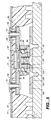
- the board mounting plate 100 is rotatably coupled to the boot mounting plate 50 via ball bearings 64 of the bearing means which are rollably supported between the female coupler sleeve 60 of the bearing means and a central male coupler 102 of the board mounting plate 100 which also forms part of the bearing means.
- the upper securement means of the binding 15 also includes mounting screws 51 which secure the boot mounting plate 50 and the snow plunger plate 40 to the bottom of the snowboot 20.
- the snow plunger plate 40 has a raised circular area attaching a tapered spring 41 and plunger 42.
- the female coupler sleeve 60 of the bearing means has a shoulder 61 and is secured to the boot mounting plate 50 by swedging 62 to the recessed center hole 53 in the plate 50.
- the female coupler sleeve 60 has tapered ball bearing holes 63 defined therein allowing the ball bearings 64 to travel inwardly without falling out.
- the bearing means also includes a snap ring 66 and stop pin 65.
- the outer bearing collar 70 is held to the female coupler sleeve 60 by the snap ring 66 and is rotatable relative to the female coupler sleeve 60 through a preset arc of rotation established by the stop pin 65 fixed to and extending from the female coupler sleeve 60 and fitting into a stop pin notch 71 formed in the top annular edge of the outer bearing collar 70.
- the outer bearing collar 70 has interior circumferentially spaced grooves 72 which allow the ball bearings 64 to roll into an open position when the binding release cable 80 of the releasing means is pulled. Upon release of the binding release cable 80, the collar spring 73 of the bearing means returns the outer bearing collar 70 back to the locked position.
- the releasing means also includes a screw 82 attaching the binding release cable 80 to the outer bearing collar 70.
- the screw 82 is held by threads 74 formed in the outer bearing collar 70 diagonally opposite from the spring hole 75 defined therein.
- the binding release collar 80 runs through an outer sleeve 83 of the releasing means which is secured to the boot mounting plate 50 by a clamp-down bracket 82 attached by one of the mounting screws 51 to the plate 50.
- the binding release cable 80 and outer sleeve 83 run through the outer edge of the boot mounting plate 50 (see Fig. 6) and then are routed through the boot sleeve 85 mounted along the exterior side of the snowboot 20.
- a ring 86 of the releasing means attached to the end of the binding release cable 80 extending above the boot sleeve 85.
- the collar spring 73 is secured to the boot mounting plate 50 by tow of the mounting screws 51 (see Fig. 6) and has an end which projects into the spring hole 75 defined in the periphery of the outer bearing collar 70.
- the lower securement means also includes mounting screws 104 which mount the board mounting plate 100 of the lower securement means to the top surface of the snowboard 10, and a male mounting bolt 101 which extends upwardly through a hole 107 in the board mounting plate 100.
- Spacers 103 are used under the central threaded male coupler 102 of the board mounting plate 100 to allow adjustment of the tightness between the snowboard 10 and the snowboot 20.
- the outer adjustment ring 104 of the lower securement means is held down by the board mounting plate 100 allowing the alignment ring 104 to be rotated and affixed to the desired alignment slot/hole 106.
- the latch mechanism 90 of the latching means is mounted to the threaded latch hole 54 in the periphery of the boot mounting plate 50 and extends therefrom toward the board mounting plate 100.
- a vertically movable plunger 90A of the latch mechanism 90 is aligned with the rotatably adjustable alignment ring 104 and therefore the selected alignment slot/hole 106.
- the latching means also has a latch release cable 92 routed through a sleeve 93 and a boot sleeve 94 mounted along an exterior side of the snowboot 20.
- a latch ring 95 is disposed above the boot sleeve 94 and affixed to the end of the latch release cable 92 for the rider to use for pulling on to remove the plunger 90A from the selected slot/hole 106 in the alignment ring 104 so as to change the angular stance position to a free rotation 360° condition, and to stay in this free rotation condition by placing the ring 95 over a release ring hook 96 mounted to the side of the snowboot 20 above the boot sleeve 94.
- Plunger 90A can be set in the up (unlatched) position. When plunger 90A in the down (latched) position it is under spring tension. The rider can thus use the step-on coupler-decoupler action in conjunction with the position of latch mechanism 90 in several ways.
- the rider may step on the board with the latch in the down position to couple the boot to the board and engage the latch with a selected slot 106. Adjustment to a different boot position can be accomplished by moving the latch to the up position, without disengaging the coupler, rotating the boot to a new position, and moving the latch to the down position to engage on a different slot 106.
- the rider may also adjust position of the boot by using only the step-on action of the coupler. With the latch in the down position, the rider may step-on the board to couple the boot to the board and engage the latch with a selected slot 106. Adjustment to a different position can be accomplished by disengaging the coupler and stepping on the board again with the boot in a different rotational position to re-couple to the board and engage the latch with a different slot 106.
- the rider may also step on the board with the latch in the down position without aligning the plunger 90A with a slot 106.
- the boot will then be coupled to the board, but there will be some rotational freedom of the boot.
- the rider may then rotate the boot, while coupled to the board, until the plunger 90A engages on a slot 106. Since the plunger 90A is under spring tension, it will automatically latch into the first slot 106 encountered during the rotational movement of the boot.
- Figs. 9 and 10 illustrate the female coupler sleeve 50 being located near the central part of the boot and the user's foot.
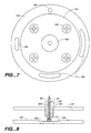
- the male coupler 102 is positioned near the longitudinal centerline of the board. With this arrangement, any overhangs of the heels and toes of a user's boot over the edges of a board are kept equal.
- the female coupler engages the male coupler such that a lower surface of the user's boot directly contacts a top surface of the snowboard. This allows forces to be directed from the ball and heel of a user's boot and foot to be transmitted directly to the surface of the board.
- Fig. 25 illustrates an arrangement 110 wherein extension of the binding release cable 80 is mounted to a pant leg so as to be more accessible to the rider in case of an incident where the rider becomes buried in the snow and is unable to reach to the boot but is able to reach to the lower leg.
- the cable so may be extended, for example, to a higher location on the upper leg or hips, if desired, and attached elsewhere on a garment of the rider.
- Figs. 26 and 27 show an alternative or modified form of the arrangement of Fig. 25 wherein an accessory release and alignment pull cable 111 is provided across the front of the boot.
- the coupling mount may comprise a ring, accommodating the two corresponding mounts to mate with the couplers on the toe and heel.
- the ring may be slidably engaged with a central mounting plate, thus providing rotational movement of the boot while coupled to the board.
Landscapes
- Footwear And Its Accessory, Manufacturing Method And Apparatuses (AREA)
- Materials Applied To Surfaces To Minimize Adherence Of Mist Or Water (AREA)
- Suspension Of Electric Lines Or Cables (AREA)
- Bridges Or Land Bridges (AREA)
- Cleaning Of Streets, Tracks, Or Beaches (AREA)
Abstract
Description
- The present invention relates to snowboarding and more specifically to a binding mounting a boot to a snowboard so as to permit free rotation of the boot and thus the position of the rider's foot relative to the snowboard while the rider is snowboarding. The binding of the present invention also incorporates features which permit quick coupling and release of the boot to and from the snowboard at a rider selected angular stance position relative to the snowboard.
- Snowboarding is a sport which combines aspects of surfing, skateboarding, and skiing. The snowboard is longer than a skateboard but shorter than a surfboard and is used as a single ski. Typically, bindings which receive the rider's boots are attached to the snowboard in a fixed position but do not have automatic release capability as do skis. Use of impact release bindings on a snowboard is considered to be undesirable because, unlike in skiing, both feet of the rider are on the same board and the release of only one foot could result in injury to the rider.
- Fixed snowboard bindings known heretofore all prevent movement between the snowboard and boots and only permit manual release of the bindings at the location of the attachment of the bindings to the snowboard. This design permitting manual release of the bindings only at the location of the snowboard itself has resulted in injury and even death. For example, three snowboarders are known to have died, at least two by suffocation, because they were unable to reach and release their bindings after becoming buried and covered by snow. The snowboard becomes an anchor, restraining the escape of the rider, when covered by snow due to the inability to easily release from the binding.
- The stance position of a rider's feet on the snowboard refers to the angular relationship formed between the midline (lengthwise) of the rider's foot and the midline (lengthwise) of the snowboard itself. The stance position is selected by the rider setting the bindings in a particular fixed relationship to the snowboard during downtime of the snowboard. The particular angle of the selected stance position is referred to in the number of degrees from a reference position in which the bindings are disposed crosswise or sideways to the length or midline of the snowboard. For example, "zero" degrees refers the bindings being set at the reference position, extending straight across the snowboard from edge to edge. Setting the bindings away from the reference position toward the nose of the snowboard is an angle greater than zero degrees while setting the bindings away from the reference position but toward the tail of the snowboard is an angle less than zero degrees which will be identified with a negative (-) sign. Typically, the front foot binding is set at a stance position between 0° to 60° and the back foot binding is set at a stance position between -5° to 55°. Freestylers set their bindings at low angles to position themselves nearly sideways in a skate/surf stance for stability: front foot binding set between 0° to 20°, and back foot binding set between 5° to -15°. Alpine riders set their bindings at the higher angles closer to a skiing position for racing and aggressive carving: front foot binding set between 40° to 60°, and back foot binding set between 35° to 55°. Free riders set their angles somewhere inbetween for a combination of stability and aggressive carving: front foot binding set between 20° to 40°, and back foot binding set between 15° and 35°. Therefore, the selected set stance position is a compromise limiting the forces transmitted to the snowboard from one set position regardless of the terrain and various conditions encountered while riding.
- US-A-5,586,779 discloses a snowboard binding device which comprises a two-part mounting, one part of which is fixed to the snowboard and the other part of which is permanently rotatably attached to the first part and carries straps which allow the boot to be fastened to the board. The two-parts of the binding can be locked against relative rotational movement in various positions allowing the user to adjust the radial position of the boots as required.
- The solution of the invention to the aforementioned problem is to provide a binding incorporating features which allow the stance position of the rider to change in a natural manner while snowboarding so as to accommodate skating, scooting, chairlift mounting, riding and dismounting, and various terrain encountered on the slope. These features of the binding mount the boot to the snowboard so as to permit the free rotation of the boot and thus the position of the rider's foot relative to the snowboard while the rider is snowboarding. Allowing a rider to transmit forces to the snowboard from any stance position, in a natural manner, improves manoeuverability and stability of the rider and snowboard and allows the rider to instantly adjust to the style necessary for each situation encountered while riding.
- Another solution of the invention is to provide a binding incorporating features which permit the rider to select the desired angular stance position relative to the snowboard. These features of the binding permit quick coupling and release of the boot to and from the snowboard at the rider-selected angular stance position.
- According to one aspect of the invention, a binding includes an upper attachment connected to a boot, a lower attachment connected to a board, a coupler attached to one of the upper and lower attachments, and a coupling mount attached to the other of the upper and lower attachments. The coupling mount and the coupler are configured to automatically engage with each other to lock the upper attachment to the lower attachment when a user wearing the boot steps onto the lower attachment and to permit rotation of the upper attachment relative to the lower attachment when the upper attachment is locked to the lower attachment.
- Additional features of the invention may include one or more of the following features.
- A release actuator is provided to disengage the coupler and the coupling mount.
- A lock is provided for locking the boot in a selected position relative to the board.
- The coupler includes a collar and a sleeve positioned within the collar such that the collar is rotatable relative to the sleeve. The release actuator is attached to the collar and is actuated to rotate the collar to disengage the coupler from the coupling mount. A spring biases the collar against rotating. A locking mechanism locks the position of the collar.
- The coupler includes ball bearings and the sleeve includes apertures in which the ball bearings are located. The collar has an inner wall defining a plurality of inner surfaces for contacting the ball bearings. The sleeve defines a passage for receiving the coupling mount. The ball bearing location within the sleeve apertures is affected by the presence of the coupling mount within the through hole. The coupler includes a spring and spring plunger located within the sleeve passage.
- The coupling mount includes a circumferential channel in which the ball bearings are partly enclosed. The coupling mount is rotatable relative to the sleeve with the ball bearings sliding along the circumferential channel during rotation of the coupling mount.
- The lower attachment includes an alignment ring with a slot cut-out. A lock attached to the boot is selectively positionable in the cut-out to lock the boot in a selected rotary position relative to the board. The lock is selectively positionable in the slot for permitting limited rotation of the boot relative to the board.
- The alignment ring may include a plurality of cut-outs. The lower attachment further includes a spacer and a mounting plate. The alignment ring is locked in a selected position relative to the mounting plate.
- A lower surface of the boot directly contacts a top surface of the board to permit forces to be directly applied from the boot to the top surface of the board.
- The coupler is located substantially at a central part of the boot and the coupler mount is located substantially at a longitudinal centerline of the board.
- According to another aspect of the invention, a coupling device is provided which includes an upper attachment connectable to a first member, a lower attachment connectable to a second member, a coupler attached to one of said upper and lower attachments, and a coupling mount attached to the other of said upper and lower attachments. The coupling mount and the coupler are configured to engage with each other by a linear motion to lock the upper attachment to the lower attachment and to permit rotation of the upper attachment relative to the lower attachment when the upper attachment is locked to the lower attachment. The coupling movement and coupler are unlocked by a twisting or rotary motion on a locking mechanism on the coupler.
- Advantages of the invention include quick coupling step-in and release of the boot to the board, the capability of rotating the boot relative to the board with the boot locked to the board, and the capability of rotating the boot to lock in a desired position relative to the board while riding.
- In the accompanying drawings:
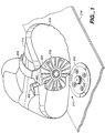
- Fig. 1 is a diagrammatic illustration of the binding of the invention shown attached to a boot and a snowboard.
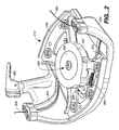
- Fig. 2 is a perspective view of an upper attachment plate of the binding of Fig. 1; Fig. 2A is a perspective view of an inner mount of the upper attachment plate; Fig. 2B is a perspective view of an outer housing of the upper attachment plate; Fig. 2C is an exploded view of the upper attachment plate; and Fig. 2D is a cross-sectional view of an interlock ring of the upper attachment plate.
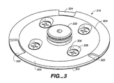
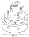
- Fig. 3 is a perspective view of a lower attachment plate of the binding of Fig. 1; and Fig. 3A is an exploded view of the lower attachment plate; and Fig. 3B is a perspective view of an alternative embodiment of an alignment ring of the lower attachment plate.
- Fig. 4 is an illustration of the locking pawl of the upper attachment plate.
- Fig. 5 is a cross-sectional view of an alternative embodiment of the boot, binding, and snowboard in a coupled position.
- Fig. 6 is a bottom plan view of the bottom of the boot of Fig. 5 with the binding in a released position.
- Fig. 7 is a top plan view of a male connector, board mounting plate and alignment ring of the binding of Fig. 5.
- Fig. 8 is a cross-sectional view of a latch mechanism, boot mounting plate and alignment ring of the binding of Fig. 5.
- Fig. 9 is a side elevational view of the boot with a coupling release mechanism of the binding of Fig. 5.
- Fig. 10 is a side elevational view of the boot with an alignment release mechanism of the binding of Fig. 5.
- Fig. 11 is a bottom plan view of the boot with inner plate stand-offs of the binding of Fig. 5.
- Fig. 12 is a cross-sectional view of the male portion of the inner plate stand-off of Fig. 11.
- Fig. 13 is a cross-sectional view of the female portion of the inner plate stand-off of Fig. 11.
- Fig. 14 is a top plan view of the inner plate stand-off of Fig. 11.
- Fig. 15 is a top plan view of the boot mounting plate of the binding of Fig. 5.
- Fig. 16 is a cross-sectional view of the snow plunger of the binding of Fig. 5.
- Fig. 17 is a top plan view of the snowboard mounting plate of the binding of Fig. 5.
- Fig. 18 is a cross-sectional view of the female coupler sleeve of the binding of Fig. 5.
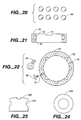
- Fig. 19 is a top plan view of the snap ring of the binding of Fig. 5.
- Fig. 20 is a plan view of eight ball bearings of the binding of Fig. 5.
- Fig. 21 is a cross-sectional view of the outer bearing collar of the binding of Fig. 5.
- Fig. 22 is a top plan view of the outer bearing collar of Fig. 21.
- Fig. 23 is a side elevational view of the male coupler of the binding of Fig. 5.
- Fig. 24 is a top plan view of the male coupler of Fig. 23.
- Fig. 25 is a side elevational view of a pant mounted release cable arrangement of the binding of Fig. 5.
- Fig. 26 is a front elevational view of a modified from of an accessory release and alignment pull cable of the pant mounted release cable arrangement of Fig. 25.
- Fig. 27 is a plan view of the accessory release and alignment pull cable of Fig. 26.
-
- Referring to Fig. 1, a snowboard binding 210 includes an
upper attachment plate 212 connected to asnowboot 214, alower attachment plate 216 connected to asnowboard 218, acoupler 220 attached toupper plate 212, and acoupling mount 222 attached tolower plate 216.Coupling mount 222 andcoupler 220 automatically engage with each other to lockupper plate 212 to thelower plate 216 when auser wearing boot 214 steps ontolower plate 216. Withupper plate 212 locked tolower plate 216,upper plate 212 is free to rotate relative tolower plate 216.Coupling mount 222 andcoupler 220 are disengaged simply by pulling up on astrap 224. This releasesupper plate 212 fromlower plate 216 permitting the user to step off ofboard 218. - Referring to Figs. 2-2B,
upper plate 212 includes anouter housing 230 and aninner mount 232. As shown in Fig. 2A (in whichinner mount 232 is shown upside down relative to its orientation in Fig. 2 and 2C),inner mount 232 includes a plurality ofholes 250 for attachinginner mount 232 to the sole 215 ofboot 214 with screws (not shown).Outer housing 230 is attached toinner mount 232 by screws (not shown) accomodated byholes 252 ofouter housing 230 and received in threadedholes 254 ofinner mount 232. - Referring to Figs. 2A and 2C,
coupler 220 includes afemale coupler sleeve 234 having anend 235 of reduced diameter which is press fit within anopening 256 defined by acircular section 257 ofinner mount 232.Coupler 220 also includes anouter bearing collar 236 having a throughbore 238 defined by aninner wall 240. When assembled,coupler sleeve 234 is located withinbore 238 of collar 236 (Fig. 2A).Ball bearings 242 are located inapertures 244 which extend throughcoupler sleeve 234. Withcollar 236 placed overcoupler sleeve 234 such that anend 246 ofcollar 236 abuts ashelf 248 ofsleeve 234 defined by an area of increaseddiameter 249,ball bearings 242 can contactinner wall 240 ofcollar 236. It is the interaction betweenball bearings 242 andinner wall 240, described further below, which acts to lockupper plate 212 tolower plate 216. -
Collar 236 is trapped betweeninner mount 232 andshelf 248 but remains rotatable relative tocoupler sleeve 234. Referring also to Fig. 2A, end 258 ofcoupler sleeve 234 is received (not a press fit) within anopening 260 ofouter housing 230. An actuating handle 262 ofcollar 236, described further below, is located within a cut-out 264 ofouter housing 230. Also attached toouter housing 230 is a lockingpawl 380, described further below. -
Coupler sleeve 234 defines a passage 270 (Fig. 2A) in which a spring 272 (Fig. 2C) is located, for example, a wave spring formed of spring stainless steel manufactured by Smally of Wheeling, Illinois, part number CO87-M6-S17. Aspring plunger 274 is slidably received withinpassage 270 and circumferentially surroundsspring 272.Passage 270 does not extend all the way throughcoupler sleeve 234 but terminates in asmaller diameter opening 273. Referring also to Fig. 2D, aninterlock ring 280 is press fit within opening 273 such that asurface 282 of the ring is flush with asurface 284 ofcoupler sleeve 234. Ascrew 286 is received within throughbore 288 ofring 280 and rests on ashelf 290 of throughbore 288.Spring plunger 274 includes an internally threadedshaft 292 in which screw 286 is threaded. When force is applied tospring plunger 274 alongarrow 294, the spring plunger moves against the force applied byspring 272, compressing the spring, and screw 286 slides within throughbore 288. - Referring to Figs. 3 and 3A,
lower plate 216 includes a spacer orboard guard 300, analignment ring 302, and a mountingplate 304. To attachlower plate 216 toboard 218,screws 306 are provided which pass throughscrew slots plate 304 andboard guard 300, respectively, and screw into binding mount holes (not shown) inboard 218. Anedge 312 of mountingplate 304 abuts against ashelf 314 ofalignment ring 302 trapping the alignment ring between mountingplate 304 andboard guard 300 whenlower plate 216 is attached toboard 218. - With
board guard 300,alignment ring 302, and mountingplate 304 assembled as shown in Fig. 3, abolt 316 attached toboard guard 300 extends through ahole 318 in mountingplate 304.Coupling mount 222 defines a threaded throughbore 320 and is attached tolower plate 216 by threading it ontobolt 316.Alignment ring 302 includes three cut-outs alignment ring 302 includes a plurality of cut-outs 327 as shown in Fig. 3B.Board guard 300 may be omitted fromlower plate 216. Alternatively, one or more board guards may be used as spacers to adjust the tightness between the board and boot. - Turning now to the locking action of
coupler 220. Referring again to Fig. 2C, withspring plunger 274 located incoupler sleeve 234, awall 340 ofspring plunger 274 acts to biasball bearings 242 radially outward withinapertures 244 and againstinner wall 240 ofcollar 236.Inner wall 240 includesoutermost surfaces 342, rampedsurfaces 344, andinnermost surfaces 346. Withball bearings 242 biased outward,collar 236 is forced to rotate such that it is the rampedsurfaces 344 ofinner wall 240 and notinnermost surfaces 346 whichabut ball bearings 242. - Referring again to Fig. 2A, an
extension spring 350, for example, formed of spring stainless steel and having an outer diameter of 0.240", a length of 1.000", and a wire diameter of 0.040", applies a force to handle 262 ofcollar 236 acting against the outward force applied byspring plunger 274. The force applied byextension spring 350 to handle 262 acts to rotatecollar 236 in the opposite direction as that ofspring plunger 274 toward a position in whichinnermost surfaces 246 ofinner wall 240abut ball bearings 242. Apin 351 attached toinner mount 232 slides within aslot 353 ofarm 262 to limit the travel ofcollar 236. - When attaching
boot 214 toboard 218,coupling mount 222 is used to apply force alongarrow 294 tospring plunger 274 acting againstspring 272. This axial load pushesspring plunger 274 further intocoupler 234 andpast ball bearings 242, and locatescoupling mount 222 inpassage 270. Withspring 350 acting to rotatecollar 236 such thatinnermost surfaces 246abut ball bearings 242biasing ball bearings 242 inward, theball bearings 242 are forced into a circumferential channel 352 (Fig. 3a) incylindrical coupling mount 222. The action ofspring 350 effectively lockscoupling mount 222 inpassage 270 by biasingball bearings 242 inward intochannel 352. Withupper plate 212 thus locked tolower plate 216, the upper plate is still free to rotate relative to the lower plate because of sliding contact betweenball bearings 242 andchannel 352. - To further insure that
upper plate 212 is locked tolower plate 216, i.e., to prevent rotation ofcollar 236 allowingball bearings 242 to move outward, lockingpawl 380 is provided with apin 382 which is received within ahole 384 incollar 236 whencollar 236 is positioned such that itsinnermost surfaces 346abut ball bearings 242. - Referring also to Fig. 4, locking
pawl 380 is mounted within a cut-out 385 inouter housing 230 by apivot post 386.Pivot post 386 extends through ahole 388 in acover 390 and is press fit into astud 392 inouter housing 230. Anextension spring 394, for example, formed of spring stainless steel and having an outer diameter of 22 mm (0.860"), a length of 29 mm (1.125"), and a wire diameter of 0.7 mm (0.029"), acts to biaspawl 380 to rotate aboutpost 386 such thatpin 382 is located withincollar hole 384 when the pin and hole are aligned. - To remove
boot 214 fromboard 218, the user pulls onstrap 224 which is attached to a cable 360 (Fig. 2A).Cable 360 is located withinchannels outer housing 230.Cable 360 is connected at oneend 361 toarm 262 byscrew 362.Cable 360 is connected at itsopposite end 363 topawl 380. Pulling oncable 360 rotatescollar 236 such thatoutermost surfaces 324 ofcollar 236 are aligned withball bearings 242, and rotatespawl 380 such thatpin 382 exitscollar hole 384, thus unlockingcoupling mount 222 fromcoupler 220. Thus, decoupling is accomplished by a rotational motion oncollar 236. By pulling up onboot 214,ball bearings 242 are forced out ofchannel 352 incoupling mount 222 and boot 214 can be removed fromboard 218. - Referring again to Fig. 1,
outer housing 230 includes alock 400 for rotationally lockingboot 214 relative to board 218. The user actuateslock 400 with ahandle 402. Referring to Figs. 2A and 2B,lock 400 includes aplunger 404 received in aside arm 406 ofouter housing 230. Rotatinghandle 402 causes plunger 404 to slide withinside arm 406 by the action of anextension spring 405, for example, formed of spring stainless steel and having an outer diameter of 6.1 mm (0.240"), a length of 25 mm (1.000"), and a wire diameter of 1.0 mm (0.040"). In its extended position,plunger 404 extends beyond thebottom surface 408 ofouter housing 230. - Referring again to Fig. 3,
plunger 404 may be extended when it is aligned with one of cut-outs amount boot 214 can be rotated relative to board 218 by the length of the cut-outs. With plunger 414 located in cut-out 322, the boot is rotationally fixed.Alignment ring 302 can be adjusted to the desired degree of foot angle. The cut-outs permit the choice of boot angle, for example, so that either the left or right boot can be the lead down the hill.Alignment ring 302 can also be interchanged with alignment rings having different width of cut-outs to permit further customization. - Referring now to Figs. 5-10 of the drawings, there is shown an exemplary embodiment of a rotatable quick coupling and release binding 15 of the present invention. The binding 15 is employed between the
boot 20 and thesnowboard 10. The binding 15 permits theboot 20 and thus the foot of the rider to be adjustable rotated from one stance position to 20°, 30°, 40° angular positions relative thereto as determined by slotted positions selected by the rider on thealignment ring 104 of the binding 15. However, rotations is not limited to these pre-slotted alignment holes 106 but can rotate 360 by simply attaching therelease ring 95 of the binding 16 to arelease ring hook 96 mounted on the side of theboot 20 allowing unlimited rotation while snow boarding. - Referring to Fig. 5, there is illustrated the exemplary embodiment of the binding 15 which basically includes: (1) upper attachment means formed by an
inner boot plate 30, snowplunger spring plate 40 andboot mounting plate 50 mounted to the bottom of thesnowboot 20; (2) lower attachment means formed by aboard mounting plate 100 mounted to the top of thesnowboard 10; (3) bearing means rotatably coupling the upper attachment means with the lower attachment means to permit rotation of thesnowboot 20 relative to thesnowboard 10, the bearing means being formed by afemale coupler sleeve 60 secured to theboot mounting plate 60 and anouter bearing collar 70 surrounding and secured to thefemale coupler sleeve 60; (4) releasing means having a bindingrelease cable 80 attached to theouter bearing collar 70 of the bearing means which when pulled moves theouter bearing collar 70 to an unlocked position and when released allows theouter bearing collar 70 to return to a locked position; and (5) latching means formed by alatch mechanism 90 mounted to theboot mounting plate 50 of the lower attachment means and having alatch release cable 92 which when pulled unlatches from theboard mounting plate 100 and permits changing of the angular stance position of the rider to a free rotation condition. Theboard mounting plate 100 is rotatably coupled to theboot mounting plate 50 viaball bearings 64 of the bearing means which are rollably supported between thefemale coupler sleeve 60 of the bearing means and a centralmale coupler 102 of theboard mounting plate 100 which also forms part of the bearing means. - As seen in Figs. 5, 6, 11, 16 and 17, the upper securement means of the binding 15 also includes mounting
screws 51 which secure theboot mounting plate 50 and thesnow plunger plate 40 to the bottom of thesnowboot 20. Thesnow plunger plate 40 has a raised circular area attaching atapered spring 41 andplunger 42. - As seen in Figs. 5 and 18, the
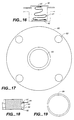
female coupler sleeve 60 of the bearing means has ashoulder 61 and is secured to theboot mounting plate 50 by swedging 62 to the recessedcenter hole 53 in theplate 50. Thefemale coupler sleeve 60 has tapered ball bearing holes 63 defined therein allowing theball bearings 64 to travel inwardly without falling out. - As seen in Figs. 5, 6 and 18-22, the bearing means also includes a
snap ring 66 and stoppin 65. Theouter bearing collar 70 is held to thefemale coupler sleeve 60 by thesnap ring 66 and is rotatable relative to thefemale coupler sleeve 60 through a preset arc of rotation established by thestop pin 65 fixed to and extending from thefemale coupler sleeve 60 and fitting into astop pin notch 71 formed in the top annular edge of theouter bearing collar 70. Theouter bearing collar 70 has interior circumferentially spacedgrooves 72 which allow theball bearings 64 to roll into an open position when the bindingrelease cable 80 of the releasing means is pulled. Upon release of the bindingrelease cable 80, thecollar spring 73 of the bearing means returns theouter bearing collar 70 back to the locked position. - The releasing means also includes a
screw 82 attaching the bindingrelease cable 80 to theouter bearing collar 70. Thescrew 82 is held bythreads 74 formed in theouter bearing collar 70 diagonally opposite from thespring hole 75 defined therein. The bindingrelease collar 80 runs through anouter sleeve 83 of the releasing means which is secured to theboot mounting plate 50 by a clamp-down bracket 82 attached by one of the mountingscrews 51 to theplate 50. The bindingrelease cable 80 andouter sleeve 83 run through the outer edge of the boot mounting plate 50 (see Fig. 6) and then are routed through theboot sleeve 85 mounted along the exterior side of thesnowboot 20. Aring 86 of the releasing means attached to the end of the bindingrelease cable 80 extending above theboot sleeve 85. Thecollar spring 73 is secured to theboot mounting plate 50 by tow of the mounting screws 51 (see Fig. 6) and has an end which projects into thespring hole 75 defined in the periphery of theouter bearing collar 70. - Referring to Figs. 5, 7, 8, 15, 23 and 24, the lower securement means also includes mounting
screws 104 which mount theboard mounting plate 100 of the lower securement means to the top surface of thesnowboard 10, and amale mounting bolt 101 which extends upwardly through ahole 107 in theboard mounting plate 100.Spacers 103 are used under the central threadedmale coupler 102 of theboard mounting plate 100 to allow adjustment of the tightness between thesnowboard 10 and thesnowboot 20. Theouter adjustment ring 104 of the lower securement means is held down by theboard mounting plate 100 allowing thealignment ring 104 to be rotated and affixed to the desired alignment slot/hole 106. - Referring to Figs. 6, 8 and 10, the
latch mechanism 90 of the latching means is mounted to the threadedlatch hole 54 in the periphery of theboot mounting plate 50 and extends therefrom toward theboard mounting plate 100. A verticallymovable plunger 90A of thelatch mechanism 90 is aligned with the rotatablyadjustable alignment ring 104 and therefore the selected alignment slot/hole 106. The latching means also has alatch release cable 92 routed through asleeve 93 and aboot sleeve 94 mounted along an exterior side of thesnowboot 20. Alatch ring 95 is disposed above theboot sleeve 94 and affixed to the end of thelatch release cable 92 for the rider to use for pulling on to remove theplunger 90A from the selected slot/hole 106 in thealignment ring 104 so as to change the angular stance position to afree rotation 360° condition, and to stay in this free rotation condition by placing thering 95 over arelease ring hook 96 mounted to the side of thesnowboot 20 above theboot sleeve 94. -
Plunger 90A can be set in the up (unlatched) position. Whenplunger 90A in the down (latched) position it is under spring tension. The rider can thus use the step-on coupler-decoupler action in conjunction with the position oflatch mechanism 90 in several ways. - The rider may step on the board with the latch in the down position to couple the boot to the board and engage the latch with a selected
slot 106. Adjustment to a different boot position can be accomplished by moving the latch to the up position, without disengaging the coupler, rotating the boot to a new position, and moving the latch to the down position to engage on adifferent slot 106. - The rider may also adjust position of the boot by using only the step-on action of the coupler. With the latch in the down position, the rider may step-on the board to couple the boot to the board and engage the latch with a selected
slot 106. Adjustment to a different position can be accomplished by disengaging the coupler and stepping on the board again with the boot in a different rotational position to re-couple to the board and engage the latch with adifferent slot 106. - The rider may also step on the board with the latch in the down position without aligning the
plunger 90A with aslot 106. The boot will then be coupled to the board, but there will be some rotational freedom of the boot. The rider may then rotate the boot, while coupled to the board, until theplunger 90A engages on aslot 106. Since theplunger 90A is under spring tension, it will automatically latch into thefirst slot 106 encountered during the rotational movement of the boot. - Figs. 9 and 10 illustrate the
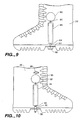
female coupler sleeve 50 being located near the central part of the boot and the user's foot. For 360° rotation of thefemale coupler sleeve 50, themale coupler 102 is positioned near the longitudinal centerline of the board. With this arrangement, any overhangs of the heels and toes of a user's boot over the edges of a board are kept equal. The female coupler engages the male coupler such that a lower surface of the user's boot directly contacts a top surface of the snowboard. This allows forces to be directed from the ball and heel of a user's boot and foot to be transmitted directly to the surface of the board. - Fig. 25 illustrates an
arrangement 110 wherein extension of the bindingrelease cable 80 is mounted to a pant leg so as to be more accessible to the rider in case of an incident where the rider becomes buried in the snow and is unable to reach to the boot but is able to reach to the lower leg. The cable so may be extended, for example, to a higher location on the upper leg or hips, if desired, and attached elsewhere on a garment of the rider. Figs. 26 and 27 show an alternative or modified form of the arrangement of Fig. 25 wherein an accessory release and alignment pullcable 111 is provided across the front of the boot. - While the above-described embodiments show a centrally mounted step-on coupler on the boot used with a single coupling mount on the board, it will be resized that multiple couplers may be used. For example, two step-on couplers may be used, one at the toe and one at the heel of the boot. The coupling mount may comprise a ring, accommodating the two corresponding mounts to mate with the couplers on the toe and heel. The ring may be slidably engaged with a central mounting plate, thus providing rotational movement of the boot while coupled to the board.
Claims (30)
- A binding, comprising:an upper attachment (212) connectable to a boot (214),a lower attachment (216) connectable to a board (218),a coupler (220) attached to one of said upper and lower attachments, anda coupling mount (222) attached to the other of said upper and lower attachments; characterised by the coupling mount and the coupler being configured to automatically engage with each other to lock the upper attachment to the lower attachment when a user wearing the boot steps onto the lower attachment and to permit rotation of the upper attachment relative to the lower attachment when the upper attachment is locked to the lower attachment.
- The binding of claim 1, further comprising a release actuator which is actuated to disengage from the coupler and the coupling mount.
- The binding of claim 2, further comprising a cable attached to said release actuator and attachable, in use, to a garment.
- The binding of claim 1, further comprising a lock (400) for locking the boot in a selected rotary position relative to the board.
- The binding of claim 1, wherein said coupler (220) is attached to the upper attachment (212).
- The binding of claim 1, wherein said upper attachment (212) comprises:a mount (232) for attachment to a sole of said boot (214).
- The binding of claim 6, further comprising an outer housing (230) attached to said mount (232).
- The binding of claim 6, wherein said coupler (220) is attached to said mount (232).
- The binding of claim 1, wherein said coupler (220) comprises a collar (236) and a sleeve (234) positioned within the collar, said collar being rotatable relative to said sleeve.
- The binding of claim 9, further comprising a release actuator attached to said collar (236), the release actuator being actuated to rotate said collar to disengage said coupler (220) and said coupling mount (232).
- The binding of claim 10, further comprising a spring biasing said collar (236) against rotating.
- The binding of claim 9, further comprising a locking mechanism (240, 242) for locking the position of said collar.
- The binding of claim 9, wherein said coupler (220) further includes ball bearings (242), said sleeve (234) including apertures (244) in which the ball bearings are located.
- The binding of claim 13, wherein said collar (236) includes an inner wall (240) defining a plurality of inner surfaces for contacting said ball bearings (242).
- The binding of claim 14, wherein said sleeve (234) defines a passage (270) for receiving said coupling mount (222), said ball bearings (242) location within said sleeve apertures (244) being affected by the presence of said coupling mount within said passage.
- The binding of claim 15, wherein said coupler (220) further comprises a spring (272) and spring plunger (274) located within said passage (270).
- The binding of claim 12, wherein said coupling mount (222) includes a circumferential channel in which said ball bearings (242) are partly enclosed, said coupling mount being rotatable relative to said sleeve (234) with said ball bearings sliding along said circumferential channel during rotation of said coupling mount.
- The binding of claim 1, wherein said coupling mount (222) is attached to said lower attachment (216).
- The binding of claim 18, wherein said coupling mount (222) is cylindrical and accommodates a circumferential channel.
- The binding of claim 1, wherein said lower attachment (216) includes an alignment ring (302).
- The binding of claim 20, wherein said alignment ring (302) includes a cut-out (322, 324, 326).
- The binding of claim 1, further comprising a lock (400) selectively positionable for locking said boot (214) in a selected rotary position relative to said board (218).
- The binding of claim 22, wherein said cut-out comprises a slot (322, 324, 326).
- The binding of claim 21 or 23, wherein said lock (400) is selectively positionable in said cut-out (322, 324, 326) for permitting limited rotation of said boot (214) relative to said board (218).
- The binding of claim 21, wherein said alignment ring includes a plurality of cut-outs (322, 324, 326).
- The binding of claim 20 or 21, wherein said lower attachment (216) further includes a mounting plate, said alignment ring (302) being locked in a selected rotated position relative to said mounting plate.
- The binding of claim 20, wherein said lower attachment further includes a spacer (300).
- The binding of claim 1, wherein a lower surface of said boot (214) contacts a top surface of said board (216) to permit forces to be directly applied from said boot to the top surface of said board.
- The binding of claim 1, wherein said coupler (220) is located substantially at a central part of said boot (214) and said coupler mount is located substantially at a longitudinal centerline of said board.
- A coupling device, comprising:wherein said coupler and coupling mount are unlocked by a rotational motion on said coupler.an upper attachment (212) connectable to a first member,a lower attachment (216) connectable to a second member,a coupler (220) attached to one of said upper and lower attachments, anda coupling mount (222) attached to the other of said upper and lower attachments; characterised in that the coupling mount and the coupler are configured to engage and lock with each other with a linear motion to lock the upper attachment to the lower attachment and to permit rotation of said upper attachment relative to said lower attachment when said upper attachment is locked to said lower attachment; and
Applications Claiming Priority (3)
| Application Number | Priority Date | Filing Date | Title |
|---|---|---|---|
| US2040496P | 1996-06-25 | 1996-06-25 | |
| US20404P | 1996-06-25 | ||
| PCT/US1997/011019 WO1997049464A1 (en) | 1996-06-25 | 1997-06-24 | Snowboard binding |
Publications (3)
| Publication Number | Publication Date |
|---|---|
| EP0934102A1 EP0934102A1 (en) | 1999-08-11 |
| EP0934102A4 EP0934102A4 (en) | 1999-11-17 |
| EP0934102B1 true EP0934102B1 (en) | 2002-05-08 |
Family
ID=21798454
Family Applications (1)
| Application Number | Title | Priority Date | Filing Date |
|---|---|---|---|
| EP97931389A Expired - Lifetime EP0934102B1 (en) | 1996-06-25 | 1997-06-24 | Snowboard binding |
Country Status (7)
| Country | Link |
|---|---|
| US (2) | US5913530A (en) |
| EP (1) | EP0934102B1 (en) |
| JP (1) | JP2000513254A (en) |
| AT (1) | ATE217206T1 (en) |
| AU (1) | AU3503097A (en) |
| DE (1) | DE69712506T2 (en) |
| WO (1) | WO1997049464A1 (en) |
Families Citing this family (60)
| Publication number | Priority date | Publication date | Assignee | Title |
|---|---|---|---|---|
| US6499757B1 (en) * | 1996-06-25 | 2002-12-31 | Richard W. Berger | Wakeboard binding |
| JP2000513254A (en) * | 1996-06-25 | 2000-10-10 | リチャード ダブリュー バーガー | Snowboard bindings |
| US6648365B1 (en) | 1997-01-08 | 2003-11-18 | The Burton Corporation | Snowboard binding |
| US6145868A (en) * | 1997-05-16 | 2000-11-14 | The Burton Corporation | Binding system for an article used to glide on snow |
| US6467794B1 (en) * | 1997-11-19 | 2002-10-22 | Emery S.A. | Device for fixing a shell for maintaining a boot of a snow surf board |
| DE19754041A1 (en) * | 1997-12-05 | 1999-06-10 | Ms Trade Handels Gmbh | Arbitrarily lockable and detachable connection device |
| US20030090072A1 (en) * | 1998-02-17 | 2003-05-15 | Cole Charles D. | Freely rotatable binding for snowboarding and other single-board sports |
| US6105995A (en) * | 1998-04-02 | 2000-08-22 | Zill; Ken | Snowboard binding |
| US6022040A (en) * | 1998-04-23 | 2000-02-08 | Buzbee; Douglas C. | Freely rotating step-in snowboard binding |
| US6155591A (en) * | 1998-06-12 | 2000-12-05 | William A. Huffman | Rotatable snowboard boot binding |
| US6302411B1 (en) | 1998-06-12 | 2001-10-16 | William A. Huffman | Rotatable snowboard boot binding |
| US6623027B1 (en) * | 1998-06-15 | 2003-09-23 | Bryce Wheeler | Release binding and brake for telemark and cross-country skis |
| US6092830A (en) * | 1998-06-15 | 2000-07-25 | Wheeler; Bryce | Release binding for telemark and cross-country skis |
| US6322095B1 (en) * | 1998-06-15 | 2001-11-27 | Bryce Wheeler | Release binding for telemark and cross-country skis |
| US6296258B2 (en) * | 1998-06-30 | 2001-10-02 | Polar Design | Snowboard shock-absorbing apparatus |
| US6655700B1 (en) * | 1998-06-30 | 2003-12-02 | Robert John Caputo | Shock-absorbing apparatus |
| IT245523Y1 (en) * | 1998-08-05 | 2002-03-22 | Marco Zanatta | SHOE ATTACHMENT DEVICE TO A SPORTS EQUIPMENT. |
| US6336650B1 (en) | 1998-08-21 | 2002-01-08 | Clayton Neil Alspaugh | Stance variable one motion step-in snowboard binding |
| FR2782654A1 (en) * | 1998-08-31 | 2000-03-03 | Fabien Jean Sophie Tillon | Boot binding for snow board; has anchor lug on boot engaging socket to on base to allow controlled rotation |
| AUPP590198A0 (en) * | 1998-09-14 | 1998-10-08 | Griplock Pty Limited | Sporting equipment binding apparatus |
| US6505841B1 (en) * | 1998-12-01 | 2003-01-14 | Dakuga Holding Ltd. | Spacer |
| USD431275S (en) * | 1999-01-07 | 2000-09-26 | Blankenbaker Jr William R | Adjustable boot binding mount |
| US7175187B2 (en) * | 1999-01-11 | 2007-02-13 | Lyden Robert M | Wheeled skate with step-in binding and brakes |
| US6422048B1 (en) * | 1999-03-15 | 2002-07-23 | Spoonfish, Inc. | Snowboard security locks |
| FR2801512B1 (en) * | 1999-11-30 | 2001-12-21 | Rossignol Sa | INTERFACE PLATE MOUNTED ON A SURFBOARD |
| IT1311665B1 (en) * | 1999-12-10 | 2002-03-14 | Benetton Spa | ADJUSTMENT DEVICE, PARTICULARLY FOR A DASNOWBOARD ATTACK. |
| US6318749B1 (en) | 2000-05-08 | 2001-11-20 | Imants Eglitis | Angularly adjustable snowboard binding mount |
| AT5260U1 (en) | 2001-03-22 | 2002-05-27 | Jolanta Dipl Ing Mekal | FLEXIBLE SNOWBOARD BINDING |
| AT411016B (en) * | 2001-08-29 | 2003-09-25 | Atomic Austria Gmbh | BINDING DEVICE FOR SPORTS EQUIPMENT, ESPECIALLY FOR A SNOWBOARD |
| US6722688B2 (en) | 2001-11-21 | 2004-04-20 | The Burton Corporation | Snowboard binding system |
| ATE290913T1 (en) * | 2001-11-21 | 2005-04-15 | Burton Corp | BINDING SUPPORT PLATE FOR A SNOWBOARD |
| FR2834909B1 (en) * | 2002-01-18 | 2004-04-09 | Emery Sa | IMPROVEMENT FOR A DEVICE FOR RETAINING A SHOE ON A SNOWBOARD OF THE SURF TYPE |
| US20030137128A1 (en) * | 2002-01-18 | 2003-07-24 | Raffo Scott W. | Multipurpose traction device |
| US6575489B1 (en) * | 2002-07-05 | 2003-06-10 | Rick Albert White | Snowboard rotatable binding conversion apparatus |
| US6916036B1 (en) | 2003-01-07 | 2005-07-12 | Kent Egli | Adjustable two-position snowboard binding mount and methods |
| US20040145155A1 (en) * | 2003-01-24 | 2004-07-29 | Dakuga Holding Ltd. | Spacer for snowboard |
| WO2004069350A2 (en) * | 2003-01-31 | 2004-08-19 | Marc Sacco | Binding adjustment system |
| JP2004305462A (en) * | 2003-04-08 | 2004-11-04 | Car Mate Mfg Co Ltd | Binding for snowboard |
| US20050194753A1 (en) * | 2004-03-08 | 2005-09-08 | Craven Richard J.Jr. | Snowboard Binding |
| US20060033293A1 (en) * | 2004-08-16 | 2006-02-16 | Tsuboi Raiden J | Sixth gear |
| US7490859B2 (en) * | 2005-06-24 | 2009-02-17 | Skis Rossignol Sa | Device for retaining a boot on a snowboard |
| US7134928B1 (en) | 2005-08-16 | 2006-11-14 | Connelly Skis, Inc. | Binding for water sports boards |
| US8192244B2 (en) * | 2005-08-16 | 2012-06-05 | Connelly Skis, Inc. | Water sports binding assembly |
| WO2007056728A2 (en) * | 2005-11-08 | 2007-05-18 | Kirnak Michael W | Automatic release attachment for kites and the like, and method of use |
| US7384048B2 (en) * | 2006-02-28 | 2008-06-10 | Paul Cerrito | Rotatable binding apparatus for a snowboard |
| BRPI0713185B1 (en) | 2007-05-02 | 2018-08-28 | Dow Global Technologies Inc | high density polyethylene composition, method for producing a high density polyethylene composition, bottle cap, method for producing a bottle cap and high density polyethylene composition |
| DE102008051334B3 (en) * | 2008-10-15 | 2010-05-06 | Otto-Von-Guericke-Universität Magdeburg | Safety binding for a mobile sports equipment |
| US7918477B2 (en) * | 2008-11-03 | 2011-04-05 | Rene Wischhusen | Snowboard binding accessory |
| US8276921B2 (en) * | 2009-09-04 | 2012-10-02 | Brendan Walker | Snowboard binding |
| US8894075B2 (en) | 2009-09-04 | 2014-11-25 | Brendan Walker | Board sport bindings |
| US8870212B2 (en) * | 2012-08-10 | 2014-10-28 | Noyes Britt Bouche, Inc. | Electromagnetically lockable rotating binding for a sportboard or the like |
| US8979097B2 (en) | 2013-03-14 | 2015-03-17 | Charles D. Cole, III | Rotatable footplate integrated with a bearing assembly imbedded in a single-board sport board |
| US9573042B2 (en) * | 2013-12-06 | 2017-02-21 | David Eugene Renshaw | Board rotating mounts and methods of making and using the same |
| US9180359B2 (en) * | 2014-01-17 | 2015-11-10 | Donough H. Deutsch | Rotatable binding system |
| US10182609B2 (en) * | 2014-07-28 | 2019-01-22 | Speedplay, Inc. | Aperture cover for bicycle cleat assembly |
| US9220970B1 (en) | 2014-11-14 | 2015-12-29 | The Burton Corporation | Snowboard binding and boot |
| WO2016077441A1 (en) | 2014-11-14 | 2016-05-19 | The Burton Corporation | Snowboard binding and boot |
| US9149711B1 (en) | 2014-11-14 | 2015-10-06 | The Burton Corporation | Snowboard binding and boot |
| CA3026280A1 (en) * | 2016-06-03 | 2017-12-07 | Kendall Sierakowski | Sport board binding system |
| US12023571B2 (en) * | 2018-11-28 | 2024-07-02 | Jeffrey P. Sabol | Rotatable sports-board binding adapter with translatable low-friction pucks |
Family Cites Families (28)
| Publication number | Priority date | Publication date | Assignee | Title |
|---|---|---|---|---|
| US3091043A (en) * | 1962-11-23 | 1963-05-28 | Jimmie D Mccorkle | Spinner attachment for shoes |
| DE2501878C2 (en) * | 1970-03-30 | 1986-01-02 | Chimera Research & Development, Inc., Holliswood, N.Y. | Safety ski bindings |
| US3707047A (en) * | 1971-02-01 | 1972-12-26 | Zygmund Nedwick | Swivel athletic shoe |
| US4463968A (en) * | 1980-06-24 | 1984-08-07 | The Regents Of The University Of California | Method for programmed release in ski bindings |
| US4371188A (en) * | 1980-06-24 | 1983-02-01 | University Of California | Method for programmed release in ski bindings |
| US4361344A (en) * | 1980-08-11 | 1982-11-30 | The Regents Of The University Of California | Ski binding with universal release |
| US5890730A (en) * | 1994-08-18 | 1999-04-06 | Switch Manufacturing | Snowboard boot and binding apparatus |
| FR2604913A1 (en) * | 1986-10-08 | 1988-04-15 | Duport Xavier | Binding for snowboards which can be modified temporarily depending on the boot used |
| US4964649A (en) * | 1989-03-15 | 1990-10-23 | Chamberlin Justin M | Snowboard boot binder attachments |
| CH676205A5 (en) * | 1989-05-04 | 1990-12-28 | Urs P Meyer | |
| US5028068A (en) * | 1989-09-15 | 1991-07-02 | Donovan Matt J | Quick-action adjustable snow boot binding mounting |
| US5190311A (en) * | 1990-02-09 | 1993-03-02 | Burton Snowboards U.S.A | Snowboard binding system |
| US5035443A (en) * | 1990-03-27 | 1991-07-30 | Kincheloe Chris V | Releasable snowboard binding |
| US5021017A (en) * | 1990-08-30 | 1991-06-04 | Wellington Leisure Products, Inc. | Water sports board with adjustable binder plates |
| AU650709B2 (en) * | 1990-12-20 | 1994-06-30 | Jack Goldberg | Improvements in footwear |
| US5277635A (en) * | 1991-12-19 | 1994-01-11 | Connelly Skis, Inc. | Water skiboard with rotatable binding |
| US5261689A (en) * | 1992-01-28 | 1993-11-16 | Burton Corporation Usa | Snowboard boot binding system |
| US5354088A (en) * | 1993-03-15 | 1994-10-11 | Vetter Dennis A | Boot binding coupling for snow boards |
| US5577755A (en) * | 1994-07-11 | 1996-11-26 | Kuusport Manufacturing Limited | Rotatable binding for snowboard |
| US5520405A (en) * | 1994-08-10 | 1996-05-28 | Bourke; Lyle J. | Snowboard binding and boot including complementary opening and binding member |
| US5520406A (en) * | 1994-08-18 | 1996-05-28 | Switch Manufacturing | Snowboard binding |
| US5722680A (en) * | 1996-05-29 | 1998-03-03 | The Burton Corporation | Step-in snowboard binding |
| US5553883A (en) * | 1995-04-06 | 1996-09-10 | Erb; George A. | Snowboard binding which permits angular reorientation of a user's foot while maintaining that foot attached to the snowboard |
| US5765853A (en) * | 1995-04-06 | 1998-06-16 | Erb; George A. | Snowboard binding which permits angular reorientation of a user's foot while maintaining that foot attached to the snowboard |
| US5586779A (en) * | 1995-06-06 | 1996-12-24 | Dawes; Paul J. | Adjustable snowboard boot binding apparatus |
| USD382320S (en) | 1995-12-22 | 1997-08-12 | Switch Manufacturing | Boot-to-binding interface for a step in snowboard binding |
| USD380289S (en) | 1995-12-22 | 1997-07-01 | Switch Manufacturing | Outsole for snowboard boot |
| JP2000513254A (en) * | 1996-06-25 | 2000-10-10 | リチャード ダブリュー バーガー | Snowboard bindings |
-
1997
- 1997-06-24 JP JP10503497A patent/JP2000513254A/en not_active Ceased
- 1997-06-24 AT AT97931389T patent/ATE217206T1/en not_active IP Right Cessation
- 1997-06-24 US US08/876,358 patent/US5913530A/en not_active Expired - Fee Related
- 1997-06-24 DE DE69712506T patent/DE69712506T2/en not_active Expired - Fee Related
- 1997-06-24 AU AU35030/97A patent/AU3503097A/en not_active Abandoned
- 1997-06-24 EP EP97931389A patent/EP0934102B1/en not_active Expired - Lifetime
- 1997-06-24 WO PCT/US1997/011019 patent/WO1997049464A1/en active IP Right Grant
-
1999
- 1999-04-23 US US09/298,356 patent/US6196569B1/en not_active Expired - Fee Related
Also Published As
| Publication number | Publication date |
|---|---|
| US5913530A (en) | 1999-06-22 |
| JP2000513254A (en) | 2000-10-10 |
| WO1997049464A1 (en) | 1997-12-31 |
| DE69712506T2 (en) | 2002-11-14 |
| EP0934102A1 (en) | 1999-08-11 |
| ATE217206T1 (en) | 2002-05-15 |
| AU3503097A (en) | 1998-01-14 |
| EP0934102A4 (en) | 1999-11-17 |
| US6196569B1 (en) | 2001-03-06 |
| DE69712506D1 (en) | 2002-06-13 |
Similar Documents
| Publication | Publication Date | Title |
|---|---|---|
| EP0934102B1 (en) | Snowboard binding | |
| WO1997049464A9 (en) | Snowboard binding | |
| US5354088A (en) | Boot binding coupling for snow boards | |
| US6994370B2 (en) | Adjustable rotatable sports board boot binding | |
| US5820155A (en) | Step-in binding system for retro-fitting to a snowboard boot binder | |
| US6062584A (en) | Double lock rotatable snowboard boot binding | |
| US5035443A (en) | Releasable snowboard binding | |
| CA2331604C (en) | Dual-locking automatic positioning interface for a snowboard boot binding | |
| US6499757B1 (en) | Wakeboard binding | |
| US6203051B1 (en) | Safety rotatable snowboard boot binding | |
| US4973073A (en) | Snowboard binding | |
| EP0779827B1 (en) | Snowboard binding | |
| US6189913B1 (en) | Step-in snowboard binding and boot therefor | |
| US5868416A (en) | Adjustable release mechanism for rotating bindings | |
| US6022040A (en) | Freely rotating step-in snowboard binding | |
| US7384048B2 (en) | Rotatable binding apparatus for a snowboard | |
| US6155591A (en) | Rotatable snowboard boot binding | |
| US20060087102A1 (en) | Releasable systems | |
| CA2258269C (en) | Snowboard binding | |
| CA2527816A1 (en) | Snowboard binding | |
| US11426647B2 (en) | Splitboard binding system with side mounting locking touring bracket | |
| US20170348585A1 (en) | Sport board binding system | |
| JP2004523293A (en) | Universal fastener device | |
| WO1999041130A1 (en) | Freely rotatable binding for snowboarding and other single-board sports | |
| EP1118359A1 (en) | Monoski |
Legal Events
| Date | Code | Title | Description |
|---|---|---|---|
| PUAI | Public reference made under article 153(3) epc to a published international application that has entered the european phase |
Free format text: ORIGINAL CODE: 0009012 |
|
| 17P | Request for examination filed |
Effective date: 19990111 |
|
| AK | Designated contracting states |
Kind code of ref document: A1 Designated state(s): AT BE CH DE DK ES FI FR GB GR IE IT LI LU MC NL PT SE |
|
| A4 | Supplementary search report drawn up and despatched |
Effective date: 19991005 |
|
| AK | Designated contracting states |
Kind code of ref document: A4 Designated state(s): AT BE CH DE DK ES FI FR GB GR IE IT LI LU MC NL PT SE |
|
| 17Q | First examination report despatched |
Effective date: 20001005 |
|
| GRAG | Despatch of communication of intention to grant |
Free format text: ORIGINAL CODE: EPIDOS AGRA |
|
| GRAG | Despatch of communication of intention to grant |
Free format text: ORIGINAL CODE: EPIDOS AGRA |
|
| GRAG | Despatch of communication of intention to grant |
Free format text: ORIGINAL CODE: EPIDOS AGRA |
|
| GRAH | Despatch of communication of intention to grant a patent |
Free format text: ORIGINAL CODE: EPIDOS IGRA |
|
| REG | Reference to a national code |
Ref country code: GB Ref legal event code: IF02 |
|
| GRAH | Despatch of communication of intention to grant a patent |
Free format text: ORIGINAL CODE: EPIDOS IGRA |
|
| GRAA | (expected) grant |
Free format text: ORIGINAL CODE: 0009210 |
|
| AK | Designated contracting states |
Kind code of ref document: B1 Designated state(s): AT BE CH DE DK ES FI FR GB GR IE IT LI LU MC NL PT SE |
|
| PG25 | Lapsed in a contracting state [announced via postgrant information from national office to epo] |
Ref country code: NL Free format text: LAPSE BECAUSE OF FAILURE TO SUBMIT A TRANSLATION OF THE DESCRIPTION OR TO PAY THE FEE WITHIN THE PRESCRIBED TIME-LIMIT Effective date: 20020508 Ref country code: IT Free format text: LAPSE BECAUSE OF FAILURE TO SUBMIT A TRANSLATION OF THE DESCRIPTION OR TO PAY THE FEE WITHIN THE PRESCRIBED TIME-LIMIT;WARNING: LAPSES OF ITALIAN PATENTS WITH EFFECTIVE DATE BEFORE 2007 MAY HAVE OCCURRED AT ANY TIME BEFORE 2007. THE CORRECT EFFECTIVE DATE MAY BE DIFFERENT FROM THE ONE RECORDED. Effective date: 20020508 Ref country code: GR Free format text: LAPSE BECAUSE OF FAILURE TO SUBMIT A TRANSLATION OF THE DESCRIPTION OR TO PAY THE FEE WITHIN THE PRESCRIBED TIME-LIMIT Effective date: 20020508 Ref country code: FI Free format text: LAPSE BECAUSE OF FAILURE TO SUBMIT A TRANSLATION OF THE DESCRIPTION OR TO PAY THE FEE WITHIN THE PRESCRIBED TIME-LIMIT Effective date: 20020508 Ref country code: BE Free format text: LAPSE BECAUSE OF FAILURE TO SUBMIT A TRANSLATION OF THE DESCRIPTION OR TO PAY THE FEE WITHIN THE PRESCRIBED TIME-LIMIT Effective date: 20020508 |
|
| REF | Corresponds to: |
Ref document number: 217206 Country of ref document: AT Date of ref document: 20020515 Kind code of ref document: T |
|
| REG | Reference to a national code |
Ref country code: CH Ref legal event code: EP |
|
| REG | Reference to a national code |
Ref country code: IE Ref legal event code: FG4D |
|
| REF | Corresponds to: |
Ref document number: 69712506 Country of ref document: DE Date of ref document: 20020613 |
|
| PG25 | Lapsed in a contracting state [announced via postgrant information from national office to epo] |
Ref country code: MC Free format text: LAPSE BECAUSE OF NON-PAYMENT OF DUE FEES Effective date: 20020624 Ref country code: LU Free format text: LAPSE BECAUSE OF NON-PAYMENT OF DUE FEES Effective date: 20020624 Ref country code: IE Free format text: LAPSE BECAUSE OF NON-PAYMENT OF DUE FEES Effective date: 20020624 |
|
| PG25 | Lapsed in a contracting state [announced via postgrant information from national office to epo] |
Ref country code: SE Free format text: LAPSE BECAUSE OF FAILURE TO SUBMIT A TRANSLATION OF THE DESCRIPTION OR TO PAY THE FEE WITHIN THE PRESCRIBED TIME-LIMIT Effective date: 20020808 Ref country code: PT Free format text: LAPSE BECAUSE OF FAILURE TO SUBMIT A TRANSLATION OF THE DESCRIPTION OR TO PAY THE FEE WITHIN THE PRESCRIBED TIME-LIMIT Effective date: 20020808 Ref country code: GB Free format text: LAPSE BECAUSE OF NON-PAYMENT OF DUE FEES Effective date: 20020808 Ref country code: DK Free format text: LAPSE BECAUSE OF FAILURE TO SUBMIT A TRANSLATION OF THE DESCRIPTION OR TO PAY THE FEE WITHIN THE PRESCRIBED TIME-LIMIT Effective date: 20020808 |
|
| REG | Reference to a national code |
Ref country code: CH Ref legal event code: NV Representative=s name: BOVARD AG PATENTANWAELTE |
|
| NLV1 | Nl: lapsed or annulled due to failure to fulfill the requirements of art. 29p and 29m of the patents act | ||
| PG25 | Lapsed in a contracting state [announced via postgrant information from national office to epo] |
Ref country code: ES Free format text: LAPSE BECAUSE OF FAILURE TO SUBMIT A TRANSLATION OF THE DESCRIPTION OR TO PAY THE FEE WITHIN THE PRESCRIBED TIME-LIMIT Effective date: 20021128 |
|
| PLBE | No opposition filed within time limit |
Free format text: ORIGINAL CODE: 0009261 |
|
| STAA | Information on the status of an ep patent application or granted ep patent |
Free format text: STATUS: NO OPPOSITION FILED WITHIN TIME LIMIT |
|
| GBPC | Gb: european patent ceased through non-payment of renewal fee |
Effective date: 20020808 |
|
| REG | Reference to a national code |
Ref country code: IE Ref legal event code: MM4A |
|
| 26N | No opposition filed |
Effective date: 20030211 |
|
| PGFP | Annual fee paid to national office [announced via postgrant information from national office to epo] |
Ref country code: CH Payment date: 20080630 Year of fee payment: 12 |
|
| PGFP | Annual fee paid to national office [announced via postgrant information from national office to epo] |
Ref country code: AT Payment date: 20080603 Year of fee payment: 12 |
|
| PGFP | Annual fee paid to national office [announced via postgrant information from national office to epo] |
Ref country code: DE Payment date: 20080731 Year of fee payment: 12 |
|
| PGFP | Annual fee paid to national office [announced via postgrant information from national office to epo] |
Ref country code: FR Payment date: 20090717 Year of fee payment: 13 |
|
| REG | Reference to a national code |
Ref country code: CH Ref legal event code: PL |
|
| PG25 | Lapsed in a contracting state [announced via postgrant information from national office to epo] |
Ref country code: LI Free format text: LAPSE BECAUSE OF NON-PAYMENT OF DUE FEES Effective date: 20090630 Ref country code: CH Free format text: LAPSE BECAUSE OF NON-PAYMENT OF DUE FEES Effective date: 20090630 |
|
| PG25 | Lapsed in a contracting state [announced via postgrant information from national office to epo] |
Ref country code: DE Free format text: LAPSE BECAUSE OF NON-PAYMENT OF DUE FEES Effective date: 20100101 Ref country code: AT Free format text: LAPSE BECAUSE OF NON-PAYMENT OF DUE FEES Effective date: 20090624 |
|
| REG | Reference to a national code |
Ref country code: FR Ref legal event code: ST Effective date: 20110228 |
|
| PG25 | Lapsed in a contracting state [announced via postgrant information from national office to epo] |
Ref country code: FR Free format text: LAPSE BECAUSE OF NON-PAYMENT OF DUE FEES Effective date: 20100630 |