EP0933344B1 - Alternating process for the metathesis of olefins - Google Patents
Alternating process for the metathesis of olefins Download PDFInfo
- Publication number
- EP0933344B1 EP0933344B1 EP98403070A EP98403070A EP0933344B1 EP 0933344 B1 EP0933344 B1 EP 0933344B1 EP 98403070 A EP98403070 A EP 98403070A EP 98403070 A EP98403070 A EP 98403070A EP 0933344 B1 EP0933344 B1 EP 0933344B1
- Authority
- EP
- European Patent Office
- Prior art keywords
- reactor
- catalyst
- regeneration
- disproportionation
- metathesis
- Prior art date
- Legal status (The legal status is an assumption and is not a legal conclusion. Google has not performed a legal analysis and makes no representation as to the accuracy of the status listed.)
- Expired - Lifetime
Links
- 150000001336 alkenes Chemical class 0.000 title claims description 39
- 238000000034 method Methods 0.000 title claims description 37
- 238000005649 metathesis reaction Methods 0.000 title claims description 32
- 239000003054 catalyst Substances 0.000 claims description 85
- 238000011069 regeneration method Methods 0.000 claims description 82
- 230000008929 regeneration Effects 0.000 claims description 79
- 238000006243 chemical reaction Methods 0.000 claims description 39
- 238000007323 disproportionation reaction Methods 0.000 claims description 24
- 229930195733 hydrocarbon Natural products 0.000 claims description 20
- 150000002430 hydrocarbons Chemical class 0.000 claims description 20
- QMMOXUPEWRXHJS-UHFFFAOYSA-N pentene-2 Natural products CCC=CC QMMOXUPEWRXHJS-UHFFFAOYSA-N 0.000 claims description 9
- VGGSQFUCUMXWEO-UHFFFAOYSA-N Ethene Chemical compound C=C VGGSQFUCUMXWEO-UHFFFAOYSA-N 0.000 claims description 8
- 239000005977 Ethylene Substances 0.000 claims description 8
- IAQRGUVFOMOMEM-UHFFFAOYSA-N but-2-ene Chemical compound CC=CC IAQRGUVFOMOMEM-UHFFFAOYSA-N 0.000 claims description 8
- 239000007788 liquid Substances 0.000 claims description 6
- 229910052702 rhenium Inorganic materials 0.000 claims description 4
- WUAPFZMCVAUBPE-UHFFFAOYSA-N rhenium atom Chemical compound [Re] WUAPFZMCVAUBPE-UHFFFAOYSA-N 0.000 claims description 4
- PNEYBMLMFCGWSK-UHFFFAOYSA-N aluminium oxide Inorganic materials [O-2].[O-2].[O-2].[Al+3].[Al+3] PNEYBMLMFCGWSK-UHFFFAOYSA-N 0.000 claims description 2
- 239000011949 solid catalyst Substances 0.000 claims description 2
- 230000001172 regenerating effect Effects 0.000 claims 2
- XNMQEEKYCVKGBD-UHFFFAOYSA-N dimethylacetylene Natural products CC#CC XNMQEEKYCVKGBD-UHFFFAOYSA-N 0.000 claims 1
- 239000007789 gas Substances 0.000 description 34
- 239000000203 mixture Substances 0.000 description 26
- IJGRMHOSHXDMSA-UHFFFAOYSA-N Atomic nitrogen Chemical compound N#N IJGRMHOSHXDMSA-UHFFFAOYSA-N 0.000 description 22
- QVGXLLKOCUKJST-UHFFFAOYSA-N atomic oxygen Chemical compound [O] QVGXLLKOCUKJST-UHFFFAOYSA-N 0.000 description 21
- 239000001301 oxygen Substances 0.000 description 21
- 229910052760 oxygen Inorganic materials 0.000 description 21
- 238000010926 purge Methods 0.000 description 17
- 229910052757 nitrogen Inorganic materials 0.000 description 11
- CURLTUGMZLYLDI-UHFFFAOYSA-N Carbon dioxide Chemical compound O=C=O CURLTUGMZLYLDI-UHFFFAOYSA-N 0.000 description 10
- XLYOFNOQVPJJNP-UHFFFAOYSA-N water Substances O XLYOFNOQVPJJNP-UHFFFAOYSA-N 0.000 description 8
- 125000004432 carbon atom Chemical group C* 0.000 description 7
- 239000012535 impurity Substances 0.000 description 7
- 239000011261 inert gas Substances 0.000 description 7
- 238000001816 cooling Methods 0.000 description 6
- IAQRGUVFOMOMEM-ONEGZZNKSA-N trans-but-2-ene Chemical compound C\C=C\C IAQRGUVFOMOMEM-ONEGZZNKSA-N 0.000 description 6
- 239000001569 carbon dioxide Substances 0.000 description 5
- 229910002092 carbon dioxide Inorganic materials 0.000 description 5
- 238000010438 heat treatment Methods 0.000 description 4
- 230000003197 catalytic effect Effects 0.000 description 3
- JRZJOMJEPLMPRA-UHFFFAOYSA-N olefin Natural products CCCCCCCC=C JRZJOMJEPLMPRA-UHFFFAOYSA-N 0.000 description 3
- QQONPFPTGQHPMA-UHFFFAOYSA-N propylene Natural products CC=C QQONPFPTGQHPMA-UHFFFAOYSA-N 0.000 description 3
- 125000004805 propylene group Chemical group [H]C([H])([H])C([H])([*:1])C([H])([H])[*:2] 0.000 description 3
- 238000011084 recovery Methods 0.000 description 3
- 125000000383 tetramethylene group Chemical group [H]C([H])([*:1])C([H])([H])C([H])([H])C([H])([H])[*:2] 0.000 description 3
- VXNZUUAINFGPBY-UHFFFAOYSA-N 1-Butene Chemical compound CCC=C VXNZUUAINFGPBY-UHFFFAOYSA-N 0.000 description 2
- XKRFYHLGVUSROY-UHFFFAOYSA-N Argon Chemical compound [Ar] XKRFYHLGVUSROY-UHFFFAOYSA-N 0.000 description 2
- VQTUBCCKSQIDNK-UHFFFAOYSA-N Isobutene Chemical compound CC(C)=C VQTUBCCKSQIDNK-UHFFFAOYSA-N 0.000 description 2
- OFBQJSOFQDEBGM-UHFFFAOYSA-N Pentane Chemical compound CCCCC OFBQJSOFQDEBGM-UHFFFAOYSA-N 0.000 description 2
- 238000001354 calcination Methods 0.000 description 2
- 150000001875 compounds Chemical class 0.000 description 2
- 230000006835 compression Effects 0.000 description 2
- 238000007906 compression Methods 0.000 description 2
- -1 ethylene, propylene Chemical group 0.000 description 2
- NNPPMTNAJDCUHE-UHFFFAOYSA-N isobutane Chemical compound CC(C)C NNPPMTNAJDCUHE-UHFFFAOYSA-N 0.000 description 2
- 238000006116 polymerization reaction Methods 0.000 description 2
- QMMOXUPEWRXHJS-HYXAFXHYSA-N (z)-pent-2-ene Chemical compound CC\C=C/C QMMOXUPEWRXHJS-HYXAFXHYSA-N 0.000 description 1
- OKTJSMMVPCPJKN-UHFFFAOYSA-N Carbon Chemical compound [C] OKTJSMMVPCPJKN-UHFFFAOYSA-N 0.000 description 1
- 239000004215 Carbon black (E152) Substances 0.000 description 1
- UFHFLCQGNIYNRP-UHFFFAOYSA-N Hydrogen Chemical compound [H][H] UFHFLCQGNIYNRP-UHFFFAOYSA-N 0.000 description 1
- 125000001118 alkylidene group Chemical group 0.000 description 1
- 229910052786 argon Inorganic materials 0.000 description 1
- 230000001174 ascending effect Effects 0.000 description 1
- 229910052799 carbon Inorganic materials 0.000 description 1
- 238000004523 catalytic cracking Methods 0.000 description 1
- 238000002485 combustion reaction Methods 0.000 description 1
- 239000000470 constituent Substances 0.000 description 1
- 238000005336 cracking Methods 0.000 description 1
- 125000004122 cyclic group Chemical group 0.000 description 1
- 238000007599 discharging Methods 0.000 description 1
- 238000001035 drying Methods 0.000 description 1
- 238000011049 filling Methods 0.000 description 1
- 239000012530 fluid Substances 0.000 description 1
- 239000001257 hydrogen Substances 0.000 description 1
- 229910052739 hydrogen Inorganic materials 0.000 description 1
- QWTDNUCVQCZILF-UHFFFAOYSA-N iso-pentane Natural products CCC(C)C QWTDNUCVQCZILF-UHFFFAOYSA-N 0.000 description 1
- 238000004519 manufacturing process Methods 0.000 description 1
- 229910000476 molybdenum oxide Inorganic materials 0.000 description 1
- IJDNQMDRQITEOD-UHFFFAOYSA-N n-butane Chemical compound CCCC IJDNQMDRQITEOD-UHFFFAOYSA-N 0.000 description 1
- QJGQUHMNIGDVPM-UHFFFAOYSA-N nitrogen group Chemical group [N] QJGQUHMNIGDVPM-UHFFFAOYSA-N 0.000 description 1
- 238000006384 oligomerization reaction Methods 0.000 description 1
- PQQKPALAQIIWST-UHFFFAOYSA-N oxomolybdenum Chemical compound [Mo]=O PQQKPALAQIIWST-UHFFFAOYSA-N 0.000 description 1
- 239000012429 reaction media Substances 0.000 description 1
- 238000003860 storage Methods 0.000 description 1
- 230000009466 transformation Effects 0.000 description 1
- 230000007704 transition Effects 0.000 description 1
- WFKWXMTUELFFGS-UHFFFAOYSA-N tungsten Chemical compound [W] WFKWXMTUELFFGS-UHFFFAOYSA-N 0.000 description 1
- 229910052721 tungsten Inorganic materials 0.000 description 1
- 239000010937 tungsten Substances 0.000 description 1
- 238000003809 water extraction Methods 0.000 description 1
Images

Classifications
-
- C—CHEMISTRY; METALLURGY
- C07—ORGANIC CHEMISTRY
- C07C—ACYCLIC OR CARBOCYCLIC COMPOUNDS
- C07C6/00—Preparation of hydrocarbons from hydrocarbons containing a different number of carbon atoms by redistribution reactions
- C07C6/02—Metathesis reactions at an unsaturated carbon-to-carbon bond
- C07C6/04—Metathesis reactions at an unsaturated carbon-to-carbon bond at a carbon-to-carbon double bond
-
- C—CHEMISTRY; METALLURGY
- C07—ORGANIC CHEMISTRY
- C07C—ACYCLIC OR CARBOCYCLIC COMPOUNDS
- C07C2521/00—Catalysts comprising the elements, oxides or hydroxides of magnesium, boron, aluminium, carbon, silicon, titanium, zirconium or hafnium
- C07C2521/02—Boron or aluminium; Oxides or hydroxides thereof
- C07C2521/04—Alumina
-
- C—CHEMISTRY; METALLURGY
- C07—ORGANIC CHEMISTRY
- C07C—ACYCLIC OR CARBOCYCLIC COMPOUNDS
- C07C2523/00—Catalysts comprising metals or metal oxides or hydroxides, not provided for in group C07C2521/00
- C07C2523/16—Catalysts comprising metals or metal oxides or hydroxides, not provided for in group C07C2521/00 of arsenic, antimony, bismuth, vanadium, niobium, tantalum, polonium, chromium, molybdenum, tungsten, manganese, technetium or rhenium
- C07C2523/32—Manganese, technetium or rhenium
- C07C2523/36—Rhenium
-
- Y—GENERAL TAGGING OF NEW TECHNOLOGICAL DEVELOPMENTS; GENERAL TAGGING OF CROSS-SECTIONAL TECHNOLOGIES SPANNING OVER SEVERAL SECTIONS OF THE IPC; TECHNICAL SUBJECTS COVERED BY FORMER USPC CROSS-REFERENCE ART COLLECTIONS [XRACs] AND DIGESTS
- Y02—TECHNOLOGIES OR APPLICATIONS FOR MITIGATION OR ADAPTATION AGAINST CLIMATE CHANGE
- Y02P—CLIMATE CHANGE MITIGATION TECHNOLOGIES IN THE PRODUCTION OR PROCESSING OF GOODS
- Y02P20/00—Technologies relating to chemical industry
- Y02P20/50—Improvements relating to the production of bulk chemicals
- Y02P20/584—Recycling of catalysts
Definitions
- the field of the invention relates to the production of olefins from at least one olefin having a carbon number different from that of the desired olefin (s).
- olefins from at least one olefin having a carbon number different from that of the desired olefin (s).
- the field of the invention relates more particularly to metathesis or the disproportionation of olefins.
- the present invention relates to a method for continuously carrying out the metathesis or disproportionation of olefins comprising at least 2 phases, a reaction phase a) carried out in a zone comprising at least one reactor containing at least one catalyst in a fixed bed and a phase b) of regeneration carried out in an area comprising at least one reactor containing at least one catalyst in a fixed bed, characterized in that at least one reactor passes from one phase to another and in this that the said reactor before the regeneration of its catalyst is isolated from the reaction circuit, the hydrocarbons, at least partly liquids contained in this reactor, being sent in a balloon buffer and reintroduced into said reactor after the regeneration phase of its catalyst.
- the invention also relates to a device for carrying out this method which comprises a reaction zone comprising at least 1 reactor containing at least one catalyst in a fixed bed and a regeneration zone containing at least one reactor containing at least one fixed bed of catalyst.
- the device often comprises from 2 to 10 reactors, preferably from 2 to 6 reactors and even more preferably from 4 reactors, when the reaction zone comprises at least 2 reactors, they are connected in series.
- the regeneration zone preferably comprises a single reactor.
- the reactors operate with upward current, they can also operate with downward current or in mixed mode, that is to say that part of the reactors operate with upward current, the other reactors operate with downward current. Up-current operation is preferred, however.
- each reactor is alternately in operation then in the regeneration phase of its catalyst.
- the transition from the operating phase of a reactor to the regeneration phase of its catalyst is carried out according to the following procedure: this reactor is isolated from the rest of the device, the hydrocarbons contained in this reactor are then evacuated then the reactor is purged .
- Said reactor is then connected to a regeneration loop and subjected to a regeneration treatment of its catalyst, at the end of this regeneration phase, the reactor and the regeneration loop are purged by at least one purge treatment for example at using an inert gas or by vacuum or successively by at least one purge using an inert gas and then by vacuum.
- One or more vacuum purges can also be performed.
- the reactor is replaced in the train of reactors in operation, preferably at the end of the series.
- Reactors in operation can be arranged in series in order any.
- the reactor containing the oldest catalyst is placed in head (in contact with the fresh charge), and the reactor containing the fresh catalyst regenerated is placed at the end of the series. This arrangement provides the best performance for load transformation.
- the reactor to be regenerated is isolated from the operating circuit and then the hydrocarbons contained in the reactor to be regenerated are emptied into a container before being inserted into the regeneration mud.
- This container can be a buffer tank provided for this purpose. After the catalyst regeneration phase, the hydrocarbons contained in this buffer tank are sent to the reactor whose catalyst has been regenerated.
- This container can also be another reactor, the procedure is as follows: the reactor for which the catalyst is to be regenerated is isolated from the operating circuit and then the hydrocarbons contained in this reactor are emptied into the reactor which has just been regenerated. The reactor whose catalyst has just been regenerated is replaced in the operating circuit, preferably at the end of the series of reactors, and the reactor emptied of its content is connected to the regeneration circuit.
- the hydrocarbons contained in the reactor are recovered. regenerate in a buffer tank.
- the use of several reactors which are removed from the operating circuit alternately to allow the regeneration of their catalyst.
- the use of several reactors makes it possible to reduce the unused catalytic mass, more precisely the catalytic mass in regeneration. This operation makes it possible to achieve a significant economic gain, especially since certain catalysts used - such as catalysts containing rhenium - are particularly expensive.
- the use of several reactors makes it possible to use catalysts of different compositions and masses and it also makes it possible to insert elements (ovens, coolers, pumps, means for controlling the composition of the effluent, etc.) according to the specific needs of the reaction.
- the catalysts used in carrying out the process according to the invention are solid catalysts preferably containing at least rhenium on a porous support preferably containing alumina.
- US Patents 4,795,734, FR 2,608,595, US 5,449,852, FR 2,740056 describe catalysts of this type.
- the olefins can also have a cyclic structure, the cycle comprising from 3 to 20 carbon atoms. An olefin can act on itself or several olefins in a mixture.
- the reactions which interest us in a preferred manner are the metathesis of ethylene and of a C4 cut containing butene-2 which produces propylene, the metathesis of ethylene and of a C5 cut containing pentene-2 which produces propylene and butenes. That is to say the following reactions:
- the device according to the invention uses 2 to 10 reactors, preferably 2 to 6 reactors and even more preferably 4 reactors.
- the method according to the invention allows continuous conversion of olefins, regeneration of the catalyst (s) of a reactor most often has a duration of about 25 to 35 hours.
- the feedstock containing the olefins is introduced into the first reactor where they undergo a first metathesis or disproportionation, this spent catalyst also allows to capture any impurities contained in the load.
- the effluent leaving the first reactor is introduced into the second reactor where it undergoes a second metathesis or disproportionation.
- the effluent thus passes through all the reactors in operation, the olefins are subject to metathesis or disproportionation in each reactor then the effluent is discharged from the reaction zone.
- the reaction conditions are as follows: a temperature of about 0 ° C to 100 ° C, preferably about 30 to 60 ° C, a pressure sufficient to maintain the effluent at least in part if not in majority in liquid form and a PPH (mass of feedstock to be treated / mass of catalyst / hour) of approximately 0.4 to 10 h -1 , preferably from 0.5 to 3 h -1 .
- PPH mass of feedstock to be treated / mass of catalyst / hour
- the regeneration of the catalyst of a reactor is carried out according to a process in several stages, each new regeneration cycle is carried out according to the procedure explained below.
- the reactor whose catalyst is to be regenerated is isolated from the reaction circuit, the hydrocarbons contained in this reactor are evacuated, this reactor is then purged by a dry and clean inert gas and then placed in the regeneration circuit.
- clean gas within the meaning of this description, it is meant that the impurity content of this gas is at most 10,000 ppm by volume, by dry gas within the meaning of this description, it is meant that the water content of this gas is at over 1000 ppm by volume, preferably a gas containing at most 1000 ppm by volume of impurities and 400 ppm by volume of water is used.
- impurities within the meaning of the present description, essentially means oxygen.
- This gas is usually chosen from the group formed by nitrogen, carbon dioxide, argon. It would not be departing from the scope of the present invention to use a mixture of at least 2 of these gases, but most often nitrogen is used.
- the purge of the reactor-regeneration loop system is carried out, this can be, for example, a purge by vacuum.
- the hydrocarbon recovery step which is optional, can be carried out in at least 2 ways: by recovery in a buffer tank or by recovery in the reactor which has just been regenerated.
- the reactor for which the catalyst is to be regenerated is then isolated from the drain section and then a purge is carried out using a dry and clean inert gas in order to eliminate any hydrocarbons remaining on the catalyst.
- This gas passes through the reactor in an ascending or descending mode, the absolute pressure inside the system is usually around 3 to 60 bar, preferably around 5 to 10 bar.
- the reactor is then connected to the regeneration circuit where it undergoes treatment in several stages.
- a regeneration gas comprising nitrogen and oxygen is introduced into the device. It is sent to an enclosure where it is dried so that its water content at the outlet of this enclosure is at most 1000 ppm by volume and preferably 400 ppm by volume.
- the gas mixture is then introduced into an enclosure supplied with air in such a way that the oxygen content of the mixture which leaves this enclosure is approximately 0.2 to 5% by volume.
- This gas mixture is then heated in an enclosure provided with a heating means and then sent to the reactor.
- the gas mixture passes through the reactor, the catalyst of which is in the regeneration phase.
- the temperature of the gas inside the reactor is usually around 300 to 500 ° C and the absolute pressure inside the reactor - regeneration loop system is usually around 3 to 60 bar, preferably from about 5 to 10 bar.
- the gas mixture leaving the reactor contains nitrogen, oxygen and carbon dioxide. Part of this gas is removed from the regeneration circuit, the rest is recycled.
- This recycled gas is cooled by any cooling means, for example with a heat exchanger, dried in such a way that its water content at the outlet of this enclosure is at most 1000 ppm by volume and preferably 400 ppm by volume. , then introduced again into the regeneration circuit.
- This first stage of the regeneration phase usually has a duration of about 1 to 10 hours, preferably about 1 to 7 hours.
- a regeneration gas comprising nitrogen and oxygen is introduced into the device. It is sent to an enclosure where it is dried so that its water content at the outlet of this enclosure is at most 1000 ppm by volume and preferably 400 ppm by volume. Then it is introduced into a enclosure supplied with air in such a way that the oxygen content of the mixture leaving this enclosure is about 1 to 22% by volume, preferably 3 to 10% by volume. The oxygen content of this mixture is preferably higher than that of the gas used in the first regeneration step.
- This mixture is then heated in an enclosure provided with a heating means then the gas mixture is sent into the reactor. The gas mixture passes through the reactor, the catalyst of which is in the phase of regeneration.
- the temperature inside the reactor is usually around 400 at 700 ° C and the absolute pressure inside the reactor system - regeneration mud is usually about 3 to 100 bar, preferably about 5 to 10 bar.
- the regeneration temperature in this step is usually at least equal to that of the first stage and it is often higher.
- the pressure in this step can be lower or higher than that of the first stage, it is often identical in the 2 steps.
- the gas mixture leaving the reactor contains nitrogen, oxygen and carbon dioxide. Part of this gas is evacuated from the regeneration, the rest is recycled. This recycled gas is cooled by any means of cooling, for example with a heat exchanger, dried in such a way that its water content at the outlet of this enclosure is at most 1000 ppm by volume and preferably 400 ppm by volume. Then this gas is again introduced into the regeneration.
- This second stage of the regeneration phase usually has a duration of approximately 1 to 10 hours, preferably approximately 1 to hours.
- a purge is carried out, for example by vacuum from the regeneration reactor-loop system, to evacuate the gas mixture, the oxygen content of which is usually around 1 to 22% by volume.
- the purpose of the purge is to reduce the oxygen content of the system to a sufficiently low value to avoid as much as possible the risks inherent in contact with oxygen and hydrocarbons under the conditions of temperature and working pressure of the process.
- the vacuum-purging of the reactor-regeneration loop system is carried out at the end of a phase of cooling the contents of the reactor.
- the system can be cooled with any means of cooling, for example with a heat exchanger.
- This purge can be carried out by various means to create the vacuum, it is possible in particular to use a liquid ring vacuum pump: vane pump, reciprocating piston pump, centrifugal pump with liquid ring, it is also possible to use according to a preferred method of the process.
- a steam ejector is also possible to use according to a preferred method of the process.
- This third step is most often carried out in 2 successive stages. Firstly, the system is opened, the pressure in the system is thus reduced to atmospheric pressure, the oxygen present is thus evacuated from the regeneration loop. In a second step, the pressure inside the loop is reduced with a means for creating the vacuum described above, the interior of the circuit is depressurized to an absolute pressure usually about 0.2 to 0 , 3 bar.
- this means of compression can be for example an alternating piston compressor or a centrifugal compressor. It would not be departing from the scope of the present invention to carry out further depressurization.
- one or more purges can be carried out between the first and the second time by an inert gas, the pressurization step is most often carried out using an inert gas such as for example the 'one of those mentioned above or a mixture of at least 2 of these gases.
- a single series of depressurization-pressurization is usually sufficient to achieve an oxygen specification in the reactor-loop system of 1000 ppm by volume. If necessary, if it is desired to obtain a lower oxygen specification in the reactor-loop system, for example around 5 ppm, at least a second vacuum purge is carried out.
- the purge of the regeneration reactor-mud system can also be carried out by a series of pressurizations at an absolute pressure usually about 6 to 8 bar and depressurization to the atmosphere using a clean inert gas and dry, nitrogen is usually used, this gas must then have contents in water and impurities presented above.
- Usually at least three sets atmospheric depressurizations-pressurizations are necessary for achieve an oxygen specification in the reactor-loop system of 1000 ppm by volume. If we want to get an oxygen specification in the system 5 ppm by volume reactor loop, usually at least 5 series of depressurizations -pressurizations to the atmosphere.
- a purge of the reactor-loop system of vacuum regeneration is a preferred mode.
- this reactor Before reconnecting the reactor to the reaction circuit, this reactor must be pressurized. Usually, the reactor pressure is adjusted using the reaction circuit outlet effluent. If the device comprising a buffer tank has been chosen, before replacing the reactor whose catalyst has just been regenerated in the operating circuit, the pressure of the reactor is adjusted using the reaction effluent and then introduced into this reactor the hydrocarbons momentarily placed in the buffer tank.
- FIG. 1 to 4 illustrate the invention without limiting its scope.
- the feed containing the olefins is treated in a reactor.
- the effluent passes through the reactor in an upward flow mode.
- the feedstock containing the olefins is introduced into the reactor R1 via line 1a, after having reacted, the effluent leaves the circuit via line 11.
- the reactor R2 is placed in the regeneration phase of its catalyst, the various regeneration gases are introduced into the reactor R2 via line 2b and exit from this reactor through line 2c.
- FIG. 2 shows the device for emptying the reactor before the regeneration of its catalyst.
- Lines 1a and 2a are respectively the lines for admitting the load to be treated and for discharging the effluent produced by the reactor R1, these lines are part of the reactor operating device detailed above (FIG. 1).
- the hydrocarbons mainly liquids, are introduced into the flask B via line 10.
- the reactor R1 is then isolated from the drain section and then a purge is carried out in order to eliminate any hydrocarbons remaining on the catalyst.
- the purge gas enters into reactor R1 via line 1d and exit from reactor R1 via line 1e.
- FIG 3 shows the catalyst regeneration device.
- the reactor whose catalyst is to be regenerated is connected to a regeneration loop.
- a regeneration gas is introduced into the device via line 8, it is then sent via line 5 into an enclosure S provided with a drying means, then it is introduced via line 6 into an enclosure M.
- the enclosure M is supplied with air via line 9.
- the mixture leaves enclosure M via line 7 and is sent to an enclosure F provided with a heating means, then the mixture is sent to reactor R1 via line 1b.
- the gas mixture passes through reactor R1 and leaves this reactor via line 1c. Part of this gas is evacuated from the regeneration circuit by line 1d, the rest is cooled by means of a heat exchanger E then introduced again into the regeneration circuit by line 5.
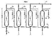
- FIG. 4 illustrates a preferred embodiment of the device according to the invention.
- the reaction zone comprises 3 reactors in series, the effluent passes successively through the reactors R1-R2-R3 in this order, according to an upward flow mode.
- the charge to be treated is introduced into the reactor R1 via line 1a.
- This charge passes through the reactor R1 and then leaves via the line 2a before being introduced into the reactor R2.
- This charge passes through the reactor R2 and then leaves via line 3a before being introduced into the reactor R3.
- This charge passes through the reactor R3 then it is evacuated from the circuit by line 11.
- the reactor R4 is placed in the regeneration phase of its catalyst, the various regeneration gases are introduced into the reactor R4 by line 4b and exit from this reactor by line 4c.
- the metathesis reactions of the following two examples are carried out with a device according to the invention comprising two reactors with a volume of 5 liters each, one is in the reaction phase while the other is in the regeneration phase.
- a device according to the invention comprising two reactors with a volume of 5 liters each, one is in the reaction phase while the other is in the regeneration phase.
- 1 kg of catalyst is placed, the catalyst used is described in the example 1 of US patent 4795734.
- the reactors are connected to a regeneration loop comprising a cooler, a compressor, a water extraction system and a oven.
- an enclosure with an air inlet is introduced into this device, then at the end of this regeneration phase we introduce in the device a vacuum pump to create a vacuum in the system.
- a mixture containing butenes mainly butene-2
- a reactor with pure ethylene (polymerization quality) at the flow rate of 0.34 kg / h .
- the reaction is carried out under the following operating conditions: a temperature of 35 ° C and an absolute pressure of 35 bar.
- the composition of the mixture to be treated is given in Table 1. compounds % in weight containing 3 or fewer carbon atoms 0.5 n-butane + i-butane 15 isobutene 0.5 butene 1 7.5 butene 2 75.5 containing 5 or more carbon atoms 1
- the regeneration phase which lasts 30 h, a hot gas containing nitrogen, oxygen and carbon dioxide flow over the catalyst.
- the oxygen content of this mixture is 0.6% by volume and the content of dry and clean nitrogen of 99.4% by volume
- the temperature inside the reactor is 450 ° C and the absolute pressure of the loop-reactor system of 6 bar.
- This stage lasts 4 hours.
- the impurities deposited during the reaction with a gas are burned poor in oxygen, then the catalyst is calcined in air. This calcination is carried out under the following conditions: the temperature inside the reactor is 550 ° C. and the absolute pressure of the loop-reactor system of 6 bar.
- the oxygen content of the loop-reactor system is 5% by volume, the nitrogen content is 70% by volume, the carbon dioxide content is 25% by volume.
- the loop and the combustion air which circulates therein are cooled by means of a heat exchanger, then a vacuum purge is carried out - the pressure is reduced up to an absolute pressure of 0.2 bar- and then filling said loop with nitrogen so that only 0.01% by volume of oxygen remains in said mud.
- the pressure in the system is then increased to an absolute pressure of 7 bar with dry and clean nitrogen containing 50 ppm by volume of water and 300 ppm by volume of impurities.
- the regeneration of the catalyst lasts 30 hours, this duration includes the periods of heating and cooling. After 30 hours, the reactor which contains the catalyst which has just been regenerated is replaced in the reaction zone and the reactor whose catalyst is spent is placed in the regeneration circuit.
- a mixture containing pentene-2 is introduced at the flow rate of 743 g / h into a reactor with pure ethylene (polymerization quality) at the flow rate of 77 g / h.
- the reaction is carried out under the following operating conditions: a temperature of 35 ° C and an absolute pressure of 35 bar.
- the composition of the mixture to be treated is given in Table 2. compounds % in weight i-pentane + n-pentane 63.7 Methyl 2 butene 2 8.3 Pentene 1 1.6 Pentene 2 15.8 other olefins with 5 or more carbon atoms 10.6
- the conversion of pentene-2 at the reactor outlet is 65% by weight, that of methyl-2 butene-2 and other olefins with 5 or more carbon atoms is 80% by weight.
- the selectivity in olefins with 3 and 4 carbon atoms compared to all products formed is 65% by weight.
- the contents of the reactor in operation are emptied into the reactor whose catalyst has just been regenerated and this latter reactor is placed in the operating circuit.
- the reactor whose catalyst is spent is placed in the regeneration circuit.
- This regeneration phase of the spent catalyst is identical in all respects to that described in Example 1.
- the reactor containing the regenerated catalyst is replaced in the reaction zone and the other reactor, of which the catalyst is spent, is placed in the regeneration zone.
Landscapes
- Chemical & Material Sciences (AREA)
- Organic Chemistry (AREA)
- Chemical Kinetics & Catalysis (AREA)
- Organic Low-Molecular-Weight Compounds And Preparation Thereof (AREA)
- Catalysts (AREA)
- Low-Molecular Organic Synthesis Reactions Using Catalysts (AREA)
Description
Le domaine de l'invention concerne la production d'oléfines à partir d'au moins une oléfine ayant un
nombre de carbone différent de celui de la ou des oléfine(s) recherchée(s). Parmi les procédés qui
permettent de réaliser cette réaction, on peut citer les procédés d'oligomérisation et les procédés de
métathèse ou de disproportionation des oléfines. Le domaine de l'invention concerne plus
particulièrement la métathèse ou la disproportionation des oléfines.
La métathèse ou disproportionation des oléfines, ou réaction de redistribution des groupements
alkylidènes entre eux, présente un grand intérêt pratique, par exemple pour le rééquilibrage entre elles
des oléfines légères issues du craquage à la vapeur d'eau ou du craquage catalytique en lit fluide (FCC),
telles que l'éthylène, le propylène et les butènes.The field of the invention relates to the production of olefins from at least one olefin having a carbon number different from that of the desired olefin (s). Among the processes which make it possible to carry out this reaction, mention may be made of oligomerization processes and metathesis or disproportionation processes of olefins. The field of the invention relates more particularly to metathesis or the disproportionation of olefins.
The metathesis or disproportionation of olefins, or reaction of redistribution of the alkylidene groups between them, is of great practical interest, for example for the rebalancing between them of light olefins resulting from cracking with steam or from catalytic cracking in a fluid bed ( FCC), such as ethylene, propylene and butenes.
Des procédés de métathèse des oléfines ont déjà été décrit notamment dans les brevets. US 4795734, FR
2608595, US 5449852 et FR 2740056: Dans le document FR 2608595, la réaction est effectuée dans un
réacteur à lit mobile de catalyseur, un traitement de régénération du catalyseur est prévu, celui-ci est
effectué comme suit : on soutire en continu ou périodiquement une partie du catalyseur, ce catalyseur est
envoyé dans un ballon accumulateur puis dans un dispositif de régénération du catalyseur. Le catalyseur
régénéré est renvoyé en tête de la zone de réaction.
Par ailleurs, le brevet US-A- 3 346 661 concerne la réaction de métathèse correspond à une mise en
oeuvre en lit fixe en présence d'un catalyseur à base d'oxyde de molybdène ou de tungstène, généralement
à température élevée de l'ordre de 300 à 350°C. La phase de régénération du catalyseur est effectuée
alternativement avec la réaction dans le même réacteur.Methods for metathesis of olefins have already been described in particular in the patents. US 4795734, FR 2608595, US 5449852 and FR 2740056: In the document FR 2608595, the reaction is carried out in a moving bed catalyst reactor, a catalyst regeneration treatment is provided, this is carried out as follows: continuously or periodically a part of the catalyst, this catalyst is sent to a storage tank and then to a catalyst regeneration device. The regenerated catalyst is returned to the top of the reaction zone.
Furthermore, US Pat. No. 3,346,661 relates to the metathesis reaction corresponds to an implementation in a fixed bed in the presence of a catalyst based on molybdenum oxide or on tungsten, generally at elevated temperature. around 300 to 350 ° C. The catalyst regeneration phase is carried out alternately with the reaction in the same reactor.
La présente invention concerne un procédé pour effectuer en continu la réaction de métathèse ou de disproportionation des oléfines comprenant au moins 2 phases, une phase a) de réaction effectuée dans une zone comprenant au moins un réacteur contenant au moins un catalyseur en lit fixe et une phase b) de régénération effectuée dans une zone comprenant au moins un réacteur contenant au moins un catalyseur en lit fixe caractérisé en ce qu'alternativement au moins un réacteur passe d'une phase à l'autre et en ce que le dit réacteur avant la mise en régénération de son catalyseur est isolé du circuit de réaction, les hydrocarbures, au moins en partie liquides contenus dans ce réacteur, étant envoyés dans un ballon tampon et réintroduits dans le dit réacteur après la phase de régénération de son catalyseur.The present invention relates to a method for continuously carrying out the metathesis or disproportionation of olefins comprising at least 2 phases, a reaction phase a) carried out in a zone comprising at least one reactor containing at least one catalyst in a fixed bed and a phase b) of regeneration carried out in an area comprising at least one reactor containing at least one catalyst in a fixed bed, characterized in that at least one reactor passes from one phase to another and in this that the said reactor before the regeneration of its catalyst is isolated from the reaction circuit, the hydrocarbons, at least partly liquids contained in this reactor, being sent in a balloon buffer and reintroduced into said reactor after the regeneration phase of its catalyst.
L'invention concerne aussi un dispositif pour la mise en oeuvre de ce procédé qui comprend
une zone réactionelle comprenant au moins 1 réacteur contenant au moins un catalyseur en lit fixe et une
zone de régénération contenant au moins un réacteur contenant au moins un lit fixe de catalyseur.
Le dispositif comprend souvent de 2 à 10 réacteurs, de préférence de 2 à 6 réacteurs et de
manière encore plus préférée de 4 réacteurs, quand la zone réactionelle comprend au moins 2
réacteurs, ils sont montés en série. La zone de régénération comprend de
manière préférée un seul réacteur. En phase de réaction, les réacteurs fonctionnent à
courant ascendant, ils peuvent aussi fonctionner à courant descendant ou en mode
mixte c'est-à-dire qu'une partie des réacteurs fonctionne à courant ascendant, les autres
réacteurs fonctionnant à courant descendant. Un fonctionnement à courant ascendant
est cependant préféré. Selon le procédé, chaque réacteur est alternativement en
fonctionnement puis en phase de régénération de son catalyseur. Le passage de la phase
de fonctionnement d'un réacteur à la phase de régénération de son catalyseur
s'effectuant selon la procédure suivante : ce réacteur est isolé du reste du dispositif, les
hydrocarbures contenus dans ce réacteur sont ensuite évacués puis le réacteur est
purgé. Ledit réacteur est ensuite connecté à une boucle de régénération et soumis à un
traitement de régénération de son catalyseur, à la fin de cette phase de régénération, le
réacteur et la boucle de régénération sont purgés par au moins un traitement de purge
par exemple à l'aide d'un gaz inerte ou par le vide ou successivement par au moins une
purge à l'aide d'un gaz inerte puis par le vide. On peut également effectuer une ou
plusieurs purges par le vide. Après la régénération du catalyseur le réacteur est replacé
dans le train des réacteurs en fonctionnement, de préférence en fin de la série.The invention also relates to a device for carrying out this method which comprises a reaction zone comprising at least 1 reactor containing at least one catalyst in a fixed bed and a regeneration zone containing at least one reactor containing at least one fixed bed of catalyst.
The device often comprises from 2 to 10 reactors, preferably from 2 to 6 reactors and even more preferably from 4 reactors, when the reaction zone comprises at least 2 reactors, they are connected in series. The regeneration zone preferably comprises a single reactor. In the reaction phase, the reactors operate with upward current, they can also operate with downward current or in mixed mode, that is to say that part of the reactors operate with upward current, the other reactors operate with downward current. Up-current operation is preferred, however. According to the process, each reactor is alternately in operation then in the regeneration phase of its catalyst. The transition from the operating phase of a reactor to the regeneration phase of its catalyst is carried out according to the following procedure: this reactor is isolated from the rest of the device, the hydrocarbons contained in this reactor are then evacuated then the reactor is purged . Said reactor is then connected to a regeneration loop and subjected to a regeneration treatment of its catalyst, at the end of this regeneration phase, the reactor and the regeneration loop are purged by at least one purge treatment for example at using an inert gas or by vacuum or successively by at least one purge using an inert gas and then by vacuum. One or more vacuum purges can also be performed. After regeneration of the catalyst, the reactor is replaced in the train of reactors in operation, preferably at the end of the series.
Les réacteurs en fonctionnement peuvent être agencés en série dans un ordre quelconque. De préférence, le réacteur contenant le catalyseur le plus âgé est placé en tête (au contact de la charge fraíche), et le réacteur contenant le catalyseur fraíchement régénéré est placé en fin de série. Cet agencement apporte les meilleures performances pour la transformation de la charge.Reactors in operation can be arranged in series in order any. Preferably, the reactor containing the oldest catalyst is placed in head (in contact with the fresh charge), and the reactor containing the fresh catalyst regenerated is placed at the end of the series. This arrangement provides the best performance for load transformation.
Suivant un mode préféré de réalisation du procédé selon l'invention, on isole le réacteur
à régénérer du circuit de fonctionnement puis on vide les hydrocarbures contenus dans
le réacteur à régénérer dans un récipient avant de l'insÈrer dans la boude de
régénération.
Ce récipient peut être un ballon tampon prévu à cet effet. Après la phase de
régénération du catalyseur, on envoie les hydrocarbures contenus dans ce ballon
tampon dans le réacteur dont le catalyseur a été régénéré.
Ce récipient peut aussi être un autre réacteur, la procédure est alors la suivante : le
réacteur dont on veut régénérer le catalyseur est isolé du circuit de fonctionnement puis
on vide les hydrocarbures contenus dans ce réacteur dans le réacteur qui vient d'être
régénéré. Le réacteur dont le catalyseur vient d'être régénéré est replacé dans le circuit
de fonctionnement, de préférence en fin de la série des réacteurs, et le réacteur vidé de
son contenu est connecté au circuit de régénération. According to a preferred embodiment of the method according to the invention, the reactor to be regenerated is isolated from the operating circuit and then the hydrocarbons contained in the reactor to be regenerated are emptied into a container before being inserted into the regeneration mud.
This container can be a buffer tank provided for this purpose. After the catalyst regeneration phase, the hydrocarbons contained in this buffer tank are sent to the reactor whose catalyst has been regenerated.
This container can also be another reactor, the procedure is as follows: the reactor for which the catalyst is to be regenerated is isolated from the operating circuit and then the hydrocarbons contained in this reactor are emptied into the reactor which has just been regenerated. The reactor whose catalyst has just been regenerated is replaced in the operating circuit, preferably at the end of the series of reactors, and the reactor emptied of its content is connected to the regeneration circuit.
De manière préférée, on récupère les hydrocarbures contenus dans le réacteur à régénérer dans un ballon tampon.Preferably, the hydrocarbons contained in the reactor are recovered. regenerate in a buffer tank.
Parmi les avantages du procédé selon l'invention, on peut noter l'utilisation de
plusieurs réacteurs que l'on sort alternativement du circuit de fonctionnement pour
permettre la régénération de leur catalyseur. Ainsi, si l'on considère l'ensemble de la
masse catalytique (l'ensemble des catalyseurs), l'utilisation de plusieurs réacteurs
permet de diminuer la masse catalytique inutilisée, plus exactement la masse
catalytique en régénération. Ce fonctionnement permet de réaliser un gain économique
important, d'autant plus que certains catalyseurs utilisés -comme les catalyseurs
contenant du rhénium- coûtent particulièrement chers. L'utilisation de plusieurs
réacteurs rend possible l'emploi de catalyseurs de compositions et de masses différentes
et elle permet aussi d'intercaler des éléments (fours, refroidisseurs, pompes, moyens de
contrôle de la composition de l'effluent...) selon les besoins spécifiques de la réaction.
On connaít différents types de catalyseurs pour la métathèse ou la disproportionation
des oléfines qui permettent d'effectuer soit des réactions de type homogène quand les
éléments constitutifs sont tous solubles dans le milieu de la réaction, soit de type
hétérogène quand au moins un des éléments est insoluble dans ledit milieu. Les
catalyseurs utilisés dans la réalisation du procédé selon l'invention sont des catalyseurs
solides contenant de préférence au moins du rhénium sur un support poreux contenant
de préférence de l'alumine. Les brevets US 4795734, FR 2608595, US 5449852, FR
2740056 décrivent des catalyseurs de ce type.Among the advantages of the process according to the invention, it may be noted the use of several reactors which are removed from the operating circuit alternately to allow the regeneration of their catalyst. Thus, if we consider all of the catalytic mass (all of the catalysts), the use of several reactors makes it possible to reduce the unused catalytic mass, more precisely the catalytic mass in regeneration. This operation makes it possible to achieve a significant economic gain, especially since certain catalysts used - such as catalysts containing rhenium - are particularly expensive. The use of several reactors makes it possible to use catalysts of different compositions and masses and it also makes it possible to insert elements (ovens, coolers, pumps, means for controlling the composition of the effluent, etc.) according to the specific needs of the reaction.
We know different types of catalysts for metathesis or disproportionation of olefins which allow to perform either reactions of homogeneous type when the constituent elements are all soluble in the reaction medium, or heterogeneous type when at least one of the elements is insoluble in said medium. The catalysts used in carrying out the process according to the invention are solid catalysts preferably containing at least rhenium on a porous support preferably containing alumina. US Patents 4,795,734, FR 2,608,595, US 5,449,852, FR 2,740056 describe catalysts of this type.
Les oléfines susceptibles de réagir en métathèse ou en disproportionation catalysée par
ce type de catalyseurs à base de rhénium supporté peuvent être des oléfines linéaires ou
ramifiées, de préférence linéaires, répondant à la formule générale :
R1 R2 C = C R3 R4 où R1, R2, R3, R4 identiques ou différents, sont l'hydrogène ou un
radical hydrocarbyle contenant de 1 à 20 atomes de carbone. Les oléfines peuvent aussi
présenter une structure cyclique, le cycle comportant de 3 à 20 atomes de carbone. On
peut faire agir une oléfine sur elle-même ou plusieurs oléfines en mélange. Les réactions
qui nous intéressent de manière préférée sont la métathèse de l'éthylène et d'une coupe
C4 contenant du butène-2 qui produit du propylène, la métathèse de l'éthylène et d'une
coupe C5 contenant du pentène-2 qui produit du propylène et des butènes. C'est-à-dire
les réactions suivantes :
![]()

R 1 R 2 C = CR 3 R 4 where R 1 , R 2 , R 3 , R 4 identical or different, are hydrogen or a hydrocarbyl radical containing from 1 to 20 carbon atoms. The olefins can also have a cyclic structure, the cycle comprising from 3 to 20 carbon atoms. An olefin can act on itself or several olefins in a mixture. The reactions which interest us in a preferred manner are the metathesis of ethylene and of a C4 cut containing butene-2 which produces propylene, the metathesis of ethylene and of a C5 cut containing pentene-2 which produces propylene and butenes. That is to say the following reactions: ![]()
Le dispositif selon l'invention met en oeuvre de 2 à 10 réacteurs, de préférence 2 à 6 réacteurs et de manière encore plus préférée 4 réacteurs. Le procédé selon l'invention permet une conversion des oléfines en continu, la régénération du ou des catalyseurs d'un réacteur a le plus souvent une durée d'environ 25 à 35 heures.The device according to the invention uses 2 to 10 reactors, preferably 2 to 6 reactors and even more preferably 4 reactors. The method according to the invention allows continuous conversion of olefins, regeneration of the catalyst (s) of a reactor most often has a duration of about 25 to 35 hours.
La charge à traiter contenant les oléfines est introduite dans le premier réacteur où elles subissent une première métathèse ou disproportionation, ce catalyseur usé permet aussi de capter les éventuelles impuretés contenues dans la charge. Dans les réalisations où au moins 2 réacteurs sont en fonctionnement, l'effluent qui sort du premier réacteur est introduit dans le deuxième réacteur où il subit une deuxième métathèse ou disproportionation. L'effluent traverse ainsi tous les réacteurs en fonctionnement, les oléfines sont soumises à des métathèses ou disproportionations dans chaque réacteur puis l'effluent est évacué de la zone de réaction.The feedstock containing the olefins is introduced into the first reactor where they undergo a first metathesis or disproportionation, this spent catalyst also allows to capture any impurities contained in the load. In the realizations where at least 2 reactors are in operation, the effluent leaving the first reactor is introduced into the second reactor where it undergoes a second metathesis or disproportionation. The effluent thus passes through all the reactors in operation, the olefins are subject to metathesis or disproportionation in each reactor then the effluent is discharged from the reaction zone.
Dans chaque réacteur, les conditions de réaction sont les suivantes : une température d'environ 0 °C à 100 °C, de préférence d'environ 30 à 60 °C, une pression suffisante pour maintenir l'effluent au moins en partie sinon en majorité sous forme liquide et une PPH (masse de charge à traiter/ masse de catalyseur/ heure) d'environ 0,4 à 10 h-1, de préférence de 0,5 à 3 h-1. En outre le faible échauffement, environ 0,5 °C par réacteur, rend inutile la présence d'éléments de refroidissement entre deux réacteurs.In each reactor, the reaction conditions are as follows: a temperature of about 0 ° C to 100 ° C, preferably about 30 to 60 ° C, a pressure sufficient to maintain the effluent at least in part if not in majority in liquid form and a PPH (mass of feedstock to be treated / mass of catalyst / hour) of approximately 0.4 to 10 h -1 , preferably from 0.5 to 3 h -1 . In addition, the low temperature rise, around 0.5 ° C per reactor, makes it unnecessary to have cooling elements between two reactors.
La régénération du catalyseur d'un réacteur s'effectue selon un procédé en plusieurs
étapes, chaque nouveau cycle de régénération est mené selon la procédure explicitée ci-après.
Le réacteur dont le catalyseur doit être régénéré est isolé du cicuit de réaction, les
hydrocarbures contenus dans ce réacteur sont évacués, ce réacteur est ensuite purgé par
un gaz inerte sec et propre puis placé dans le circuit de régénération. Par gaz propre au
sens de la présente description, on entend que la teneur en impuretés de ce gaz est au
plus 10000 ppm en volume, par gaz sec au sens de la présente description, on entend
que la teneur en eau de ce gaz est au plus 1000 ppm en volume, de préférence, on
emploie un gaz contenant au plus 1000 ppm en volume d'impuretés et 400 ppm en
volume d'eau. Par impuretés, au sens de la présente description, on entend
essentiellement l'oxygène. Ce gaz est habituellement choisi dans le groupe formé par
l'azote, le dioxyde de carbone, l'argon. On ne sortirait pas du cadre de la présente
invention en utilisant un mélange d'au moins 2 de ces gaz mais le plus souvent on
utilise de l'azote. En fin de régénération, la purge du système réacteur-boucle de
régénération est effectuée, ce peut être, par exemple une purge par le vide.
Avant la mise en régénération du catalyseur, les hydrocarbures contenus dans le
réacteur dont le catalyseur doit être régénéré sont évacués. L'étape de récupération des
hydrocarbures, qui est facultative, peut être effectuée selon au moins 2 façons : par
récupération dans un ballon tampon ou par récupération dans le réacteur qui vient
d'être régénéré.The regeneration of the catalyst of a reactor is carried out according to a process in several stages, each new regeneration cycle is carried out according to the procedure explained below. The reactor whose catalyst is to be regenerated is isolated from the reaction circuit, the hydrocarbons contained in this reactor are evacuated, this reactor is then purged by a dry and clean inert gas and then placed in the regeneration circuit. By clean gas within the meaning of this description, it is meant that the impurity content of this gas is at most 10,000 ppm by volume, by dry gas within the meaning of this description, it is meant that the water content of this gas is at over 1000 ppm by volume, preferably a gas containing at most 1000 ppm by volume of impurities and 400 ppm by volume of water is used. By impurities, within the meaning of the present description, essentially means oxygen. This gas is usually chosen from the group formed by nitrogen, carbon dioxide, argon. It would not be departing from the scope of the present invention to use a mixture of at least 2 of these gases, but most often nitrogen is used. At the end of regeneration, the purge of the reactor-regeneration loop system is carried out, this can be, for example, a purge by vacuum.
Before the catalyst is regenerated, the hydrocarbons contained in the reactor whose catalyst is to be regenerated are removed. The hydrocarbon recovery step, which is optional, can be carried out in at least 2 ways: by recovery in a buffer tank or by recovery in the reactor which has just been regenerated.
Le réacteur dont on doit régénérer le catalyseur est ensuite isolé de la section de vidange
puis on effectue une purge au moyen d'un gaz inerte sec et propre afin d'éliminer les
éventuels hydrocarbures restés sur le catalyseur. Ce gaz traverse le réacteur selon un
mode ascendant ou descendant, la pression absolue à l'intérieur du système est
habituellement d'environ de 3 à 60 bar, de préférence d'environ 5 à 10 bar.
Le réacteur est ensuite connecté au circuit de régénération où il subit un traitement en
plusieurs étapes.
Suivant une première étape, un gaz de régénération comprenant de l'azote et de
l'oxygène est introduit dans le dispositif. Il est envoyé dans une enceinte o_ il est séché
de telle façon que sa teneur en eau à la sortie de cette enceinte soit au plus de 1000 ppm
en volume et de préférence de 400 ppm en volume. Puis il est introduit dans une
enceinte alimentée en air de telle façon que la teneur en oxygène du mélange qui sort de
cette enceinte soit d'environ 0,2 à 5 % en volume. Ce mélange de gaz est ensuite chauffé
dans une enceinte munie d'un moyen de chauffage puis envoyé dans le réacteur. Le
mélange de gaz traverse le réacteur dont le catalyseur est en phase de régénération. La
température du gaz à l'intérieur du réacteur est habituellement d'environ 300 à 500 °C
et la pression absolue à l'intérieur du système réacteur - boucle de régénération est
habituellement d'environ de 3 à 60 bar, de préférence d'environ 5 à 10 bar. Le mélange
de gaz qui sort du réacteur contient de l'azote, de l'oxygène et du dioxyde de carbone.
Une partie de ce gaz est évacuée du circuit de régénération, le reste est recyclé. Ce gaz
recyclé est refroidi par tout moyen de refroidissement, par exemple avec un échangeur
de chaleur, séché de telle façon que sa teneur en eau à la sortie de cette enceinte soit au
plus de 1000 ppm en volume et de préférence de 400 ppm en volume, puis introduit à
nouveau dans le circuit de régénération. Cette première étape de la phase de
régénération a habituellement une durée d'environ 1 à 10 heures, de préférence
d'environ 1 à 7 heures.The reactor for which the catalyst is to be regenerated is then isolated from the drain section and then a purge is carried out using a dry and clean inert gas in order to eliminate any hydrocarbons remaining on the catalyst. This gas passes through the reactor in an ascending or descending mode, the absolute pressure inside the system is usually around 3 to 60 bar, preferably around 5 to 10 bar.
The reactor is then connected to the regeneration circuit where it undergoes treatment in several stages.
According to a first step, a regeneration gas comprising nitrogen and oxygen is introduced into the device. It is sent to an enclosure where it is dried so that its water content at the outlet of this enclosure is at most 1000 ppm by volume and preferably 400 ppm by volume. Then it is introduced into an enclosure supplied with air in such a way that the oxygen content of the mixture which leaves this enclosure is approximately 0.2 to 5% by volume. This gas mixture is then heated in an enclosure provided with a heating means and then sent to the reactor. The gas mixture passes through the reactor, the catalyst of which is in the regeneration phase. The temperature of the gas inside the reactor is usually around 300 to 500 ° C and the absolute pressure inside the reactor - regeneration loop system is usually around 3 to 60 bar, preferably from about 5 to 10 bar. The gas mixture leaving the reactor contains nitrogen, oxygen and carbon dioxide. Part of this gas is removed from the regeneration circuit, the rest is recycled. This recycled gas is cooled by any cooling means, for example with a heat exchanger, dried in such a way that its water content at the outlet of this enclosure is at most 1000 ppm by volume and preferably 400 ppm by volume. , then introduced again into the regeneration circuit. This first stage of the regeneration phase usually has a duration of about 1 to 10 hours, preferably about 1 to 7 hours.
Suivant une deuxième étape, un gaz de régénération comprenant de l'azote et de l'oxygène est introduit dans le dispositif. Il est envoyé dans une enceinte o_ il est séché de telle façon que sa teneur en eau à la sortie de cette enceinte soit au plus de 1000 ppm en volume et de préférence de 400 ppm en volume. Puis il est introduit dans une enceinte alimentée en air de façon telle que la teneur en oxygène du mélange qui sort de cette enceinte soit d'environ 1 à 22 % en volume, de préférence de 3 à 10 % en volume. La teneur en oxygène de ce mélange est de préférence supérieure à celle du gaz employé dans la première étape de régénération. Ce mélange est ensuite chauffé dans une enceinte munie d'un moyen de chauffage puis le mélange de gaz est envoyé dans le réacteur. Le mélange de gaz traverse le réacteur dont le catalyseur est en phase de régénération. La température à l'intérieur du réacteur est habituellement d'environ 400 à 700 °C et la pression absolue à l'intérieur du système réacteur - boude de régénération est habituellement d'environ de 3 à 100 bar, de préférence d'environ 5 à 10 bar. La température de régénération dans cette étape est habituellement au moins égale à celle de la première étape et elle est souvent plus élevée. La pression dans cette étape peut être plus basse ou plus élevée que celle de la première étape, elle est souvent identique dans les 2 étapes. Le mélange de gaz qui sort du réacteur contient de l'azote, de l'oxygène et du dioxyde de carbone. Une partie de ce gaz est évacuée du circuit de régénération, le reste est recyclé. Ce gaz recyclé est refroidi par tout moyen de refroidissement, par exemple avec un échangeur de chaleur, séché de telle façon que sa teneur en eau à la sortie de cette enceinte soit au plus de 1000 ppm en volume et de préférence de 400 ppm en volume. Puis ce gaz est introduit à nouveau dans le circuit de régénération. Cette deuxième étape de la phase de régénération a habituellement une durée d'environ 1 à 10 heures, de préférence d'environ 1 à heures.According to a second step, a regeneration gas comprising nitrogen and oxygen is introduced into the device. It is sent to an enclosure where it is dried so that its water content at the outlet of this enclosure is at most 1000 ppm by volume and preferably 400 ppm by volume. Then it is introduced into a enclosure supplied with air in such a way that the oxygen content of the mixture leaving this enclosure is about 1 to 22% by volume, preferably 3 to 10% by volume. The oxygen content of this mixture is preferably higher than that of the gas used in the first regeneration step. This mixture is then heated in an enclosure provided with a heating means then the gas mixture is sent into the reactor. The gas mixture passes through the reactor, the catalyst of which is in the phase of regeneration. The temperature inside the reactor is usually around 400 at 700 ° C and the absolute pressure inside the reactor system - regeneration mud is usually about 3 to 100 bar, preferably about 5 to 10 bar. The regeneration temperature in this step is usually at least equal to that of the first stage and it is often higher. The pressure in this step can be lower or higher than that of the first stage, it is often identical in the 2 steps. The gas mixture leaving the reactor contains nitrogen, oxygen and carbon dioxide. Part of this gas is evacuated from the regeneration, the rest is recycled. This recycled gas is cooled by any means of cooling, for example with a heat exchanger, dried in such a way that its water content at the outlet of this enclosure is at most 1000 ppm by volume and preferably 400 ppm by volume. Then this gas is again introduced into the regeneration. This second stage of the regeneration phase usually has a duration of approximately 1 to 10 hours, preferably approximately 1 to hours.
Suivant une troisième étape, on effectue une purge par exemple par le vide du
système réacteur-boucle de régénération pour évacuer le mélange de gaz dont la
teneur en oxygène est habituellement d'environ de 1 à 22 % en volume. La purge
a pour but de diminuer la teneur en oxygène du système à une valeur
suffisament basse pour éviter au maximum les risques inhérents au contact de
l'oxygène et des hydrocarbures dans les conditions de température et de pression
de travail du procédé. La purge par le vide du système réacteur-boucle de
régénération est effectuée à l'issue d'une phase de refroidissement du contenu du
réacteur. Le système peut être refroidi avec tout moyen de refroidissement, par
exemple avec un échangeur de chaleur. Cette purge peut être effectuée par
différents moyens pour faire le vide, on peut notamment utiliser une pompe à
vide à anneau liquide : pompe à palette, pompe à piston réciproque, pompe
centrifuge à anneau liquide, on peut aussi utiliser selon un mode préféré du
procédé selon l'invention un éjecteur à vapeur.
Cette troisième étape est le plus souvent effectuée en 2 temps successifs.
Dans un premier temps, on ouvre le système, on ramène ainsi la pression dans le
système à la pression atmosphérique, l'oxygène présent est ainsi évacué de la
boucle de régénération. Dans un deuxième temps, on diminue la pression à
l'intérieur de la boucle avec un moyen pour faire le vide décrit ci-dessus, on
dépressurise l'intérieur du circuit jusqu'à une pression absolue habituellement
d'environ 0,2 à 0,3 bar. Puis on augmente à nouveau la pression à l'intérieur du
circuit avec un moyen de compression interne ou externe au dispositif jusqu'à
une pression absolue d'environ 6 à 8 bar, ce moyen de compression peut être par
exemple un compresseur alternatif à piston ou un compresseur centrifuge. On ne
sortirait pas du cadre de la présente invention en effectuant une dépressurisation
plus poussée. De même dans le cadre de la présente invention on peut effectuer,
entre le premier et le deuxième temps, une ou plusieurs purges par un gaz inerte,
l'étape de pressurisation est le plus souvent effectuée en utilisant un gaz inerte tel
que par exemple l'un de ceux cités ci-devant ou un mélange d'au moins 2 de ces
gaz.
Une seule série de dépressurisation- pressurisation suffit habituellement pour
atteindre une spécification en oxygène dans le système réacteur-boucle de 1000
ppm en volume. Au besoin, si on veut obtenir une spécification en oxygène dans
le système réacteur-boucle plus faible et par exemple d'environ 5 ppm, on
effectue au moins une deuxième purge par le vide.In a third step, a purge is carried out, for example by vacuum from the regeneration reactor-loop system, to evacuate the gas mixture, the oxygen content of which is usually around 1 to 22% by volume. The purpose of the purge is to reduce the oxygen content of the system to a sufficiently low value to avoid as much as possible the risks inherent in contact with oxygen and hydrocarbons under the conditions of temperature and working pressure of the process. The vacuum-purging of the reactor-regeneration loop system is carried out at the end of a phase of cooling the contents of the reactor. The system can be cooled with any means of cooling, for example with a heat exchanger. This purge can be carried out by various means to create the vacuum, it is possible in particular to use a liquid ring vacuum pump: vane pump, reciprocating piston pump, centrifugal pump with liquid ring, it is also possible to use according to a preferred method of the process. according to the invention a steam ejector.
This third step is most often carried out in 2 successive stages.
Firstly, the system is opened, the pressure in the system is thus reduced to atmospheric pressure, the oxygen present is thus evacuated from the regeneration loop. In a second step, the pressure inside the loop is reduced with a means for creating the vacuum described above, the interior of the circuit is depressurized to an absolute pressure usually about 0.2 to 0 , 3 bar. Then the pressure inside the circuit is increased again with a means of compression internal or external to the device up to an absolute pressure of approximately 6 to 8 bar, this means of compression can be for example an alternating piston compressor or a centrifugal compressor. It would not be departing from the scope of the present invention to carry out further depressurization. Similarly, in the context of the present invention, one or more purges can be carried out between the first and the second time by an inert gas, the pressurization step is most often carried out using an inert gas such as for example the 'one of those mentioned above or a mixture of at least 2 of these gases.
A single series of depressurization-pressurization is usually sufficient to achieve an oxygen specification in the reactor-loop system of 1000 ppm by volume. If necessary, if it is desired to obtain a lower oxygen specification in the reactor-loop system, for example around 5 ppm, at least a second vacuum purge is carried out.
La purge du système réacteur-boude de régénération peut aussi être effectuée par une série de pressurisations à une pression absolue habituellement d'environ 6 à 8 bar et de dépressurisations à l'atmosphère en utilisant un gaz inerte propre et sec, on utilise habituellement de l'azote, ce gaz doit alors présenter des teneurs en eau et en impuretés présentées ci-devant. Habituellement au moins trois séries de dépressurisations-pressurisations à l'atmosphère sont nécessaires pour atteindre une spécification en oxygène dans le système réacteur-boucle de 1000 ppm en volume. Si on veut obtenir une spécification en oxygène dans le système réacteur-boucle de 5 ppm en volume, on doit habituellement effectuer au moins 5 séries de dépressurisations -pressurisations à l'atmosphère.The purge of the regeneration reactor-mud system can also be carried out by a series of pressurizations at an absolute pressure usually about 6 to 8 bar and depressurization to the atmosphere using a clean inert gas and dry, nitrogen is usually used, this gas must then have contents in water and impurities presented above. Usually at least three sets atmospheric depressurizations-pressurizations are necessary for achieve an oxygen specification in the reactor-loop system of 1000 ppm by volume. If we want to get an oxygen specification in the system 5 ppm by volume reactor loop, usually at least 5 series of depressurizations -pressurizations to the atmosphere.
Dans le procédé selon l'invention, une purge du système réacteur-boucle de régénération par le vide est un mode préféré.In the process according to the invention, a purge of the reactor-loop system of vacuum regeneration is a preferred mode.
Avant de reconnecter le réacteur au circuit de réaction, on doit pressuriser ce
réacteur. Habituellement, on adapte la pression du réacteur en utilisant l'effluent
de sortie du circuit de réaction.
Si on a choisi le dispositif comprenant un ballon tampon, avant de replacer le réacteur
dont le catalyseur vient d'être régénéré dans le circuit de fonctionnement, on adapte la
pression du réacteur en utilisant l'effluent de la réaction puis on introduit dans ce
réacteur les hydrocarbures momentanément placés dans le ballon tampon.Before reconnecting the reactor to the reaction circuit, this reactor must be pressurized. Usually, the reactor pressure is adjusted using the reaction circuit outlet effluent.
If the device comprising a buffer tank has been chosen, before replacing the reactor whose catalyst has just been regenerated in the operating circuit, the pressure of the reactor is adjusted using the reaction effluent and then introduced into this reactor the hydrocarbons momentarily placed in the buffer tank.
Les figures 1 à 4 illustrent l'invention sans en limiter la portée.Figures 1 to 4 illustrate the invention without limiting its scope.
Suivant la figure 1, la charge contenant les oléfines est traitée dans un réacteur. Selon
cette figure, l'effluent traverse le réacteur selon un mode à flux ascendant.
La charge à traiter contenant les oléfines est introduite dans le réacteur R1 par la ligne
1a, après avoir réagi, l'effluent sort du circuit par la ligne 11.
Simultanément le réacteur R2 est placé en phase de régénération de son catalyseur, les
différents gaz de régénération sont introduits dans le réacteur R2 par la ligne 2b et
ressortent de ce réacteur par la ligne 2c.According to FIG. 1, the feed containing the olefins is treated in a reactor. According to this figure, the effluent passes through the reactor in an upward flow mode.
The feedstock containing the olefins is introduced into the reactor R1 via
Simultaneously the reactor R2 is placed in the regeneration phase of its catalyst, the various regeneration gases are introduced into the reactor R2 via
La figure 2 présente le dispositif de vidange du réacteur avant la mise en régénération
de son catalyseur. Dans cette description, on a choisi de présenter la vidange du
réacteur R1.
Les lignes 1a et 2a sont respectivement les lignes d'admission de la charge à traiter et
d'évacuation de l'effluent produit par le réacteur R1, ces lignes font partie du dispositif
de fonctionnement des réacteurs détaillé ci-dessus (figure 1). Avant la mise en
régénération du catalyseur, les hydrocarbures, en majorité liquides, sont introduits dans
le ballon B par la ligne 10.FIG. 2 shows the device for emptying the reactor before the regeneration of its catalyst. In this description, we have chosen to present the emptying of reactor R1.
Le réacteur R1 est ensuite isolé de la section de vidange puis on effectue une purge afin
d'éliminer les éventuels hydrocarbures restés sur le catalyseur. Le gaz de purge entre
dans le réacteur R1 par la ligne 1d et sort du réacteur R1 par la ligne 1e. The reactor R1 is then isolated from the drain section and then a purge is carried out in order to
eliminate any hydrocarbons remaining on the catalyst. The purge gas enters
into reactor R1 via
A la fin de la phase de régénération du catalyseur du réacteur R1, les
hydrocarbures stockés dans le ballon tampon B sont introduits dans le réacteur
R1 par la ligne 10.At the end of the regeneration phase of the catalyst of reactor R1, the
hydrocarbons stored in buffer tank B are introduced into the reactor
R1 via
La figure 3 présente le dispositif de régénération du catalyseur. Dans cette description,
on a choisi de présenter la régénération du catalyseur contenu dans le réacteur R1.
Le réacteur dont le catalyseur doit être régénéré est connecté à une boucle de
régénération.
Un gaz de régénération est introduit dans le dispositif par la ligne 8, il est ensuite
envoyé par la ligne 5 dans une enceinte S munie d'un moyen de séchage puis il est
introduit par la ligne 6 dans une enceinte M. L'enceinte M est alimentée en air par la
ligne 9. Le mélange sort de l'enceinte M par la ligne 7 et est envoyé dans une enceinte F
munie d'un moyen de chauffage puis le mélange est envoyé dans le réacteur R1 par la
ligne 1b. Le mélange de gaz traverse le réacteur R1 et sort de ce réacteur par la ligne 1c.
Une partie de ce gaz est évacuée du circuit de régénération par la ligne 1d, le reste est
refroidi au moyen d'un échangeur de chaleur E puis introduit à nouveau dans le circuit
de régénération par la ligne 5.Figure 3 shows the catalyst regeneration device. In this description, we have chosen to present the regeneration of the catalyst contained in the reactor R1.
The reactor whose catalyst is to be regenerated is connected to a regeneration loop.
A regeneration gas is introduced into the device via line 8, it is then sent via line 5 into an enclosure S provided with a drying means, then it is introduced via
La figure 4 illustre un mode préféré de réalisation du dispositif selon l'invention.
Selon ce mode de réalisation, la zone de réaction comprend 3 réacteurs en série,
l'effluent parcours successivement les réacteurs R1-R2-R3 dans cet ordre, selon un
mode à flux ascendant. La charge à traiter est introduite dans le réacteur R1 par la
ligne 1a. Cette charge traverse le réacteur R1 puis ressort par la ligne 2a avant
d'être introduite dans le réacteur R2. Cette charge traverse le réacteur R2 puis
ressort par la ligne 3a avant d'être introduite dans le réacteur R3. Cette charge
traverse le réacteur R3 puis elle est évacuée du circuit par la ligne 11.
Simultanément le réacteur R4 est placé en phase de régénération de son
catalyseur, les différents gaz de régénération sont introduits dans le réacteur R4
par la ligne 4b et ressortent de ce réacteur par la ligne 4c.FIG. 4 illustrates a preferred embodiment of the device according to the invention. According to this embodiment, the reaction zone comprises 3 reactors in series, the effluent passes successively through the reactors R1-R2-R3 in this order, according to an upward flow mode. The charge to be treated is introduced into the reactor R1 via
Simultaneously the reactor R4 is placed in the regeneration phase of its catalyst, the various regeneration gases are introduced into the reactor R4 by
Les exemples présentés ci-après illustrent l'invention sans en limiter la portée.The examples presented below illustrate the invention without limiting its scope.
Pour des raisons de commodité de mise en oeuvre au laboratoire, les exemples suivants ont été réalisés avec 2 réacteurs dont un en fonctionnement. Cependant les réalisations industrielles comprennent généralement un nombre plus important de réacteurs en fonctionnement, de façon préférée, on utilisera un dispositif comprenant 3 réacteurs en fonctionnement et un seul réacteur en régénération, ainsi qu'un ballon tampon.For reasons of convenience in the laboratory, the examples The following were carried out with 2 reactors, one of which in operation. However industrial achievements generally include a higher number important reactors in operation, preferably, we will use a device comprising 3 reactors in operation and a single reactor in regeneration, as well as a buffer tank.
Les réactions de métathèse des deux exemples qui suivent sont réalisées avec un dispositif selon l'invention comprenant deux réacteurs de volume 5 litres chacun, un est en phase de réaction pendant que l'autre est en phase de régénération. Dans chacun de ces réacteurs, on place 1 kg de catalyseur, le catalyseur utilisé est décrit dans l'exemple 1 du brevet US 4795734. Les réacteurs sont reliés à une boucle de régénération comprenant un refroidisseur, un compresseur, un système d'extraction d'eau et un four. Durant la phase de régénération, une enceinte munie d'une entrée d'air est introduite dans ce dispositif, puis en fin de cette phase de régénération on introduit dans le dispositif une pompe à vide pour faire le vide dans le système.The metathesis reactions of the following two examples are carried out with a device according to the invention comprising two reactors with a volume of 5 liters each, one is in the reaction phase while the other is in the regeneration phase. In each of these reactors, 1 kg of catalyst is placed, the catalyst used is described in the example 1 of US patent 4795734. The reactors are connected to a regeneration loop comprising a cooler, a compressor, a water extraction system and a oven. During the regeneration phase, an enclosure with an air inlet is introduced into this device, then at the end of this regeneration phase we introduce in the device a vacuum pump to create a vacuum in the system.
Durant la phase de réaction, un mélange contenant des butènes, principalement du
butène-2 est introduit au débit de 0,9 kg/h dans un réacteur avec de l'éthylène pur
(qualité polymérisation) au débit de 0,34 kg/h. La réaction est effectuée dans les
conditions opératoires suivantes : une température de 35°C et une pression absolue de
35 bar. La composition du mélange à traiter est consignée dans le tableau 1.
La conversion du butène-2 est de 61% en masse en sortie du réacteur. La sélectivité en propylène est de 95% en masse. The conversion of butene-2 is 61% by mass at the outlet of the reactor. Selectivity in propylene is 95% by mass.
Après 30 heures de fonctionnement, on vide le contenu du réacteur qui était en fonctionnement dans le réacteur dont le catalyseur vient d'être régénéré et on place ce dernier réacteur dans le circuit de fonctionnement. Le réacteur dont le catalyseur est usé est placé dans le circuit de régénération.After 30 hours of operation, the contents of the reactor which was in operation in the reactor whose catalyst has just been regenerated and we place this last reactor in the operating circuit. The reactor whose catalyst is spent is placed in the regeneration circuit.
Durant la phase de régénération qui dure 30 h, un gaz chaud contenant de l'azote, de l'oxygène et du dioxyde de carbone circule sur le catalyseur. Au début de la phase de régénération, la teneur en oxygène de ce mélange est de 0,6% en volume et la teneur en azote sec et propre de 99,4 % en volume, la température à l'intérieur du réacteur est de 450°C et la pression absolue du système boucle-réacteur de 6 bar. Cette étape dure 4 heures. On brûle ainsi d'abord les impuretés déposées lors de la réaction avec un gaz pauvre en oxygène, puis on calcine le catalyseur sous air. Cette calcination est effectuée dans les conditions suivantes : la température à l'intérieur du réacteur est de 550°C et la pression absolue du système boucle-réacteur de 6 bar. A l'issu de cette calcination, qui dure 2 heures, la teneur en oxygène du système boucle-réacteur est de 5 % en volume, la teneur en azote est de 70 % en volume, la teneur en dioxyde de carbone est de 25% en volume. On refroidit la boucle et l'air de combustion qui y circule au moyen d'un échangeur de chaleur, puis on effectue une purge par le vide -on diminue la pression jusqu'à une pression absolue de 0,2 bar- et on remplit ensuite ladite boucle avec de l'azote de telle façon qu'il ne reste dans ladite boude que 0,01 % en volume d'oxygène. On augmente ensuite la pression dans le système jusqu'à une pression absolue de 7 bar avec de l'azote sec et propre contenant 50 ppm en volume d'eau et 300 ppm en volume d'impuretés.During the regeneration phase which lasts 30 h, a hot gas containing nitrogen, oxygen and carbon dioxide flow over the catalyst. At the start of the regeneration, the oxygen content of this mixture is 0.6% by volume and the content of dry and clean nitrogen of 99.4% by volume, the temperature inside the reactor is 450 ° C and the absolute pressure of the loop-reactor system of 6 bar. This stage lasts 4 hours. First, the impurities deposited during the reaction with a gas are burned poor in oxygen, then the catalyst is calcined in air. This calcination is carried out under the following conditions: the temperature inside the reactor is 550 ° C. and the absolute pressure of the loop-reactor system of 6 bar. At the end of this calcination, which lasts 2 hours, the oxygen content of the loop-reactor system is 5% by volume, the nitrogen content is 70% by volume, the carbon dioxide content is 25% by volume. The loop and the combustion air which circulates therein are cooled by means of a heat exchanger, then a vacuum purge is carried out - the pressure is reduced up to an absolute pressure of 0.2 bar- and then filling said loop with nitrogen so that only 0.01% by volume of oxygen remains in said mud. The pressure in the system is then increased to an absolute pressure of 7 bar with dry and clean nitrogen containing 50 ppm by volume of water and 300 ppm by volume of impurities.
La régénération du catalyseur dure 30 heures, cette durée comprend les périodes de chauffage et de refroidissement. Au bout de 30 heures, le réacteur qui contient le catalyseur qui vient d'être régénéré est replacé dans la zone de réaction et le réacteur dont le catalyseur est usé est placé dans le circuit de régénération.The regeneration of the catalyst lasts 30 hours, this duration includes the periods of heating and cooling. After 30 hours, the reactor which contains the catalyst which has just been regenerated is replaced in the reaction zone and the reactor whose catalyst is spent is placed in the regeneration circuit.
Durant la phase de réaction, un mélange contenant du pentène-2 est introduit au débit
de 743 g/h dans un réacteur avec de l'éthylène pur (qualité polymérisation) au débit de
77 g/h. La réaction est effectuée dans les conditions opératoires suivantes : une
température de 35°C et une pression absolue de 35 bar. La composition du mélange à
traiter est consignée dans le tableau 2.
La conversion du pentène-2 en sortie du réacteur est de 65% en poids, celle du méthyl-2 butène-2 et des autres oléfines à 5 atomes de carbone ou plus est de 80 % en poids. La sélectivité en oléfines à 3 et 4 atomes de carbone par rapport à l'ensemble des produits formés est de 65% en poids.The conversion of pentene-2 at the reactor outlet is 65% by weight, that of methyl-2 butene-2 and other olefins with 5 or more carbon atoms is 80% by weight. The selectivity in olefins with 3 and 4 carbon atoms compared to all products formed is 65% by weight.
Après 30 heures de fonctionnement, on vide le contenu du réacteur en fonctionnement
dans le réacteur dont le catalyseur vient d'être régénéré et on place ce dernier réacteur
dans le circuit de fonctionnement. Le réacteur dont le catalyseur est usé est placé dans le
circuit de régénération.
Cette phase de régénération du catalyseur usé est identique en tous points à celle
décrite dans l'exemple 1. A la fin de la régénération du catalyseur, on replace le réacteur
contenant le catalyseur régénéré dans la zone de réaction et l'autre réacteur, dont le
catalyseur est usé, est placé dans la zone de régénération.After 30 hours of operation, the contents of the reactor in operation are emptied into the reactor whose catalyst has just been regenerated and this latter reactor is placed in the operating circuit. The reactor whose catalyst is spent is placed in the regeneration circuit.
This regeneration phase of the spent catalyst is identical in all respects to that described in Example 1. At the end of the regeneration of the catalyst, the reactor containing the regenerated catalyst is replaced in the reaction zone and the other reactor, of which the catalyst is spent, is placed in the regeneration zone.
Claims (17)
- A process for continuous metathesis or disproportionation of olefins, comprising at least two phases, a reaction phase a) carried out in a zone comprising at least one reactor containing at least one fixed bed of catalyst and a regeneration phase b) carried out in a zone comprising at least one reactor containing at least one fixed bed of catalyst, characterized in that at least one reactor passes from one phase to the other in alternation and in that said reactor, before the passage to regeneration of the catalyst therein, is isolated from the reaction circuit, the hydrocarbons at least partially liquid contained in this reactor being sent to a surge drum and reintroduced into said reactor after the regeneration phase of its catalyst.
- A process for continuous metathesis or disproportionation of olefins according to claim 1, in which the reaction phase is carried out in a zone containing at least two reactors in series.
- A process for continuous metathesis or disproportionation of olefins according to claim 1 or claim 2, in which the regeneration phase is carried out in a zone containing a single reactor.
- A process for continuous metathesis or disproportionation of olefins according to any one of claims 1 to 3, characterized in that passage from the operating phase of one reactor to the regeneration phase for its catalyst is accomplished as follows: the reactor for which the catalyst is to be regenerated is isolated from the remainder of the apparatus, the hydrocarbons contained in that reactor are evacuated, then said reactor is purged.
- A process for continuous metathesis or disproportionation of olefins according to any one of claims 1 to 4, characterized in that the reactor for which the catalyst has just been regenerated and the regeneration loop are purged, said reactor then being replaced in the series of operating reactors.
- A process for continuous metathesis or disproportionation of olefins according to any one of claims 1 to 5, characterized in that before regenerating the catalyst in a reactor, said reactor is isolated from the reaction circuit, then the hydrocarbons contained in the reactor are emptied into a further reactor, preferably into the reactor for which the catalyst has just been regenerated.
- A process for continuous metathesis or disproportionation of olefins according to any one of claims 1 to 5, characterized in that before regenerating the catalyst of a reactor, said reactor is isolated from the reaction circuit then the hydrocarbons contained in that reactor are emptied into a surge drum, and after regeneration of its catalyst, the hydrocarbons in the drum are re-introduced into said reactor, the reactor then being replaced in the series of operating reactors.
- A process for continuous metathesis or disproportionation of olefins according to any one of claims 1 to 7, characterized in that the reactor for which the catalyst has just been regenerated is replaced in the series of operating reactors, at the end of that series.
- A process for continuous metathesis or disproportionation of olefins according to any one of claims 1 to 8, characterized in that the catalyst regeneration phase is terminated by at least one depressurisation step for the reactor-regeneration loop system, the pressure of the system being taken to an absolute pressure of 0.2 to 0.3 bars, followed by at least one pressurisation step for the system to an absolute pressure of about 6 to 8 bars.
- A process for continuous metathesis or disproportionation of olefins according to any one of claims 1 to 9, characterized in that a C4 cut containing 2-butene and ethylene is reacted.
- A process for continuous metathesis or disproportionation of olefins according to any one of claims 1 to 9, characterized in that a C5 cut containing 2-pentene and ethylene is reacted.
- A process for continuous metathesis or disproportionation of olefins according to any one of claims 1 to 11, characterized in that the reactors operate in riser mode.
- A process for continuous metathesis or disproportionation of olefins according to any one of claims 1 to 11, characterized in that the reactors operate in dropper mode.
- A process for continuous metathesis or disproportionation of olefins according to any one of claims 1 to 11, characterized in that a portion of the reactors operate in riser mode, and the other reactors operate in dropper mode.
- A process for continuous metathesis or disproportionation of olefins according to any one of claims 1 to 14, characterized in that the catalysts used are solid catalysts containing at least rhenium on a porous alumina-containing support.
- An apparatus for carrying out the process claimed in any one of claims 1 to 15, characterized in that it comprises a reaction zone comprising at least one reactor containing at least one fixed bed of catalyst and a regeneration zone containing at least one reactor containing at least one fixed bed of catalyst.
- An apparatus for carrying out the process of claim 16, characterized in that the reaction zone comprises at least two reactors in series.
Applications Claiming Priority (2)
| Application Number | Priority Date | Filing Date | Title |
|---|---|---|---|
| FR9715743A FR2772022B1 (en) | 1997-12-10 | 1997-12-10 | ALTERNATE PROCESS FOR OLEFIN METATHESIS |
| FR9715743 | 1997-12-10 |
Publications (2)
| Publication Number | Publication Date |
|---|---|
| EP0933344A1 EP0933344A1 (en) | 1999-08-04 |
| EP0933344B1 true EP0933344B1 (en) | 2002-09-18 |
Family
ID=9514509
Family Applications (1)
| Application Number | Title | Priority Date | Filing Date |
|---|---|---|---|
| EP98403070A Expired - Lifetime EP0933344B1 (en) | 1997-12-10 | 1998-12-07 | Alternating process for the metathesis of olefins |
Country Status (9)
| Country | Link |
|---|---|
| US (1) | US6281402B1 (en) |
| EP (1) | EP0933344B1 (en) |
| KR (1) | KR100523181B1 (en) |
| CN (1) | CN1200918C (en) |
| DE (1) | DE69808040T2 (en) |
| ES (1) | ES2184210T3 (en) |
| FR (1) | FR2772022B1 (en) |
| MY (1) | MY126576A (en) |
| TW (1) | TW575553B (en) |
Families Citing this family (12)
| Publication number | Priority date | Publication date | Assignee | Title |
|---|---|---|---|---|
| DE10309070A1 (en) * | 2003-03-03 | 2004-09-16 | Basf Ag | Process for the regeneration of Re207 doped supported catalysts |
| DE10344690A1 (en) * | 2003-09-25 | 2005-04-14 | Basf Ag | Process for the preparation of 1,7-octadiene and its use |
| US20060129013A1 (en) * | 2004-12-09 | 2006-06-15 | Abazajian Armen N | Specific functionalization and scission of linear hydrocarbon chains |
| EP2829317A1 (en) | 2013-07-23 | 2015-01-28 | Borealis AG | Improved catalyst bed configuration for olefin production |
| EP2848300A1 (en) | 2013-09-13 | 2015-03-18 | Borealis AG | Process for olefin production by metathesis and reactor system therefore |
| EP2862629A1 (en) | 2013-10-15 | 2015-04-22 | Borealis AG | Catalyst and process for olefin metathesis reaction |
| CN104557399B (en) * | 2013-10-28 | 2017-07-14 | 中国石油化工股份有限公司 | The method that amylene is disproportionated propylene processed with ethene |
| EP2873459A1 (en) | 2013-11-14 | 2015-05-20 | Borealis AG | Catalyst bed configuration for olefin conversion and process for obtaining olefins |
| EP2886189A1 (en) | 2013-12-20 | 2015-06-24 | Borealis AG | Process for olefin production by metathesis and reactor system therefor |
| EP2891643A1 (en) | 2014-01-02 | 2015-07-08 | Borealis AG | Process for obtaining olefins by metathesis |
| FR3077073B1 (en) * | 2018-01-24 | 2020-02-07 | IFP Energies Nouvelles | ETHANE VAPOCRACKING PROCESS |
| FR3097779A1 (en) * | 2019-06-26 | 2021-01-01 | IFP Energies Nouvelles | Hydrocarbon catalytic treatment reactor with semi-continuous catalyst replacement |
Family Cites Families (10)
| Publication number | Priority date | Publication date | Assignee | Title |
|---|---|---|---|---|
| CH298872A (en) * | 1950-03-02 | 1954-05-31 | Techn Steiner Walter Dr Sc | Process for the synthesis of hydrocarbons. |
| FR1199407A (en) * | 1957-09-27 | 1959-12-14 | Cie Francaise Procedes Houdry | Method and device for the catalytic conversion of hydrocarbons |
| US3261879A (en) * | 1963-09-27 | 1966-07-19 | Phillips Petroleum Co | Olefin disproportionation |
| US3365512A (en) * | 1964-09-23 | 1968-01-23 | Phillips Petroleum Co | Dehydration of a gas employed in cooling a catalyst |
| US3676520A (en) * | 1964-12-31 | 1972-07-11 | Phillips Petroleum Co | Conversion of olefins |
| FR91345E (en) * | 1965-11-22 | 1968-09-09 | ||
| US4072629A (en) * | 1973-12-18 | 1978-02-07 | Shell Oil Company | Regeneration of alkene disproportionation catalyst |
| FR2608595B1 (en) * | 1986-12-17 | 1989-04-28 | Inst Francais Du Petrole | PROCESS FOR THE METATHESIS OF OLEFINS |
| US5336393A (en) * | 1991-06-12 | 1994-08-09 | Idemitsu Kosan Co., Ltd. | Process for catalytically converting organic compounds |
| US5491277A (en) * | 1993-12-28 | 1996-02-13 | Uop | Mixed-phase solid bed hydrocarbon alkylation process |
-
1997
- 1997-12-10 FR FR9715743A patent/FR2772022B1/en not_active Expired - Fee Related
-
1998
- 1998-12-07 EP EP98403070A patent/EP0933344B1/en not_active Expired - Lifetime
- 1998-12-07 DE DE69808040T patent/DE69808040T2/en not_active Expired - Lifetime
- 1998-12-07 ES ES98403070T patent/ES2184210T3/en not_active Expired - Lifetime
- 1998-12-09 MY MYPI98005552A patent/MY126576A/en unknown
- 1998-12-10 US US09/208,585 patent/US6281402B1/en not_active Expired - Lifetime
- 1998-12-10 KR KR1019980054101A patent/KR100523181B1/en not_active IP Right Cessation
- 1998-12-10 CN CNB981265278A patent/CN1200918C/en not_active Expired - Fee Related
-
1999
- 1999-02-12 TW TW87120532A patent/TW575553B/en not_active IP Right Cessation
Also Published As
| Publication number | Publication date |
|---|---|
| TW575553B (en) | 2004-02-11 |
| KR100523181B1 (en) | 2006-01-27 |
| EP0933344A1 (en) | 1999-08-04 |
| MY126576A (en) | 2006-10-31 |
| DE69808040T2 (en) | 2003-02-06 |
| FR2772022B1 (en) | 2000-01-14 |
| ES2184210T3 (en) | 2003-04-01 |
| CN1223991A (en) | 1999-07-28 |
| US6281402B1 (en) | 2001-08-28 |
| DE69808040D1 (en) | 2002-10-24 |
| CN1200918C (en) | 2005-05-11 |
| KR19990062956A (en) | 1999-07-26 |
| FR2772022A1 (en) | 1999-06-11 |
Similar Documents
| Publication | Publication Date | Title |
|---|---|---|
| EP0933344B1 (en) | Alternating process for the metathesis of olefins | |
| EP0769323B1 (en) | Rhenium and aluminium supported catalysts, their preparation and use for the metathesis of olefins | |
| WO2006051185A1 (en) | Reaction device having a number of moving bed zones with supplementing in each regenerated or fresh catalyst zone | |
| FR2747054A1 (en) | PROCESS FOR CONVERTING SYNTHESIS GAS IN THE PRESENCE OF A CATALYST BASED ON COBALT AND TITANIUM | |
| EP0334742A1 (en) | Liquid phase selective hydrogenation of a normally gaseous feedstock containing ethylene, acetylene and naptha | |
| EP0184517B1 (en) | Hydrocarbon feed catalytic cracking processes and apparatuses | |
| EP0302771A1 (en) | Process for the simultaneous removal of arsenic and carbon oxysulfide from a cut of unsaturated hydrocarbons in the liquid phase | |
| JP2020094179A (en) | Low viscosity poly-α-olefin lubricating oil and method for synthesizing the same | |
| EP0308302A1 (en) | Process for the production of olefin oligomers using a modified mordenite catalyst | |
| EP0679709B1 (en) | Process for the conversion of natural gas into hydrocarbons | |
| EP1024123B1 (en) | Process for the metathesis of olefins in presence of a stablising agent for the catalyst | |
| EP0611185B1 (en) | Continuous process for the isomerisation of olefins comprising the regeneration of the catalyst | |
| CH375145A (en) | Process for preparing a catalytic composition for the polymerization of polymerizable hydrocarbons | |
| EP1094049B1 (en) | Process for synthesising hydrocarbons from synthesis gas in the presence of a Raney metal alloy dispersed in a liquid phase | |
| EP1110931B1 (en) | Process and device for the alkylation of isobutane with light olefins | |
| EP1252259B1 (en) | Method and device for producing aromatic compounds comprising catalyst reduction | |
| EP1110933B1 (en) | Process for the selective production of propylene from hydrocarbon cuts with four carbon atoms | |
| FR2781696A1 (en) | LIQUID PHASE CONVERSION PROCESS WITH A CATALYST INTO A MOBILE BED WITH USE OF A LIFT-STRIPPER AND INSTALLATION FOR METATHESIS | |
| EP0375547B1 (en) | Process for upgrading the off-gases from a catalytic cracking process and lowering the benzene content of gasolines | |
| FR2504121A1 (en) | Light olefin oligomerisation - using boron tri:fluoride catalyst on alumina support | |
| JP2858952B2 (en) | Multistage olefin isomerization | |
| EP0479646B1 (en) | Catalytic downflow fluid bed conversion process of a charge consisted essentially of at least one oxygen containing compound | |
| FR2676747A1 (en) | PROCESS FOR THE PRODUCTION OF LIQUID HYDROCARBONS FROM NATURAL GAS IN THE PRESENCE OF A CATALYST BASED ON ZEOLITHE AND NOBLE METALS. | |
| EP0659717B1 (en) | Method of alkylating the side chain of alkyl-substituted aromatic hydrocarbons | |
| BE882886Q (en) | CATALYZED GASIFICATION PROCESS FOR THE PREPARATION OF METHANE |
Legal Events
| Date | Code | Title | Description |
|---|---|---|---|
| PUAI | Public reference made under article 153(3) epc to a published international application that has entered the european phase |
Free format text: ORIGINAL CODE: 0009012 |
|
| AK | Designated contracting states |
Kind code of ref document: A1 Designated state(s): DE ES GB IT NL |
|
| AX | Request for extension of the european patent |
Free format text: AL;LT;LV;MK;RO;SI |
|
| 17P | Request for examination filed |
Effective date: 20000204 |
|
| AKX | Designation fees paid |
Free format text: DE ES GB IT NL |
|
| 17Q | First examination report despatched |
Effective date: 20001219 |
|
| GRAG | Despatch of communication of intention to grant |
Free format text: ORIGINAL CODE: EPIDOS AGRA |
|
| GRAG | Despatch of communication of intention to grant |
Free format text: ORIGINAL CODE: EPIDOS AGRA |
|
| GRAH | Despatch of communication of intention to grant a patent |
Free format text: ORIGINAL CODE: EPIDOS IGRA |
|
| GRAH | Despatch of communication of intention to grant a patent |
Free format text: ORIGINAL CODE: EPIDOS IGRA |
|
| GRAA | (expected) grant |
Free format text: ORIGINAL CODE: 0009210 |
|
| AK | Designated contracting states |
Kind code of ref document: B1 Designated state(s): DE ES GB IT NL |
|
| REG | Reference to a national code |
Ref country code: GB Ref legal event code: FG4D Free format text: NOT ENGLISH |
|
| REF | Corresponds to: |
Ref document number: 69808040 Country of ref document: DE Date of ref document: 20021024 |
|
| GBT | Gb: translation of ep patent filed (gb section 77(6)(a)/1977) |
Effective date: 20021119 |
|
| REG | Reference to a national code |
Ref country code: ES Ref legal event code: FG2A Ref document number: 2184210 Country of ref document: ES Kind code of ref document: T3 |
|
| PLBE | No opposition filed within time limit |
Free format text: ORIGINAL CODE: 0009261 |
|
| STAA | Information on the status of an ep patent application or granted ep patent |
Free format text: STATUS: NO OPPOSITION FILED WITHIN TIME LIMIT |
|
| 26N | No opposition filed |
Effective date: 20030619 |
|
| PGFP | Annual fee paid to national office [announced via postgrant information from national office to epo] |
Ref country code: NL Payment date: 20081219 Year of fee payment: 11 |
|
| REG | Reference to a national code |
Ref country code: NL Ref legal event code: V1 Effective date: 20100701 |
|
| PG25 | Lapsed in a contracting state [announced via postgrant information from national office to epo] |
Ref country code: NL Free format text: LAPSE BECAUSE OF NON-PAYMENT OF DUE FEES Effective date: 20100701 |
|
| REG | Reference to a national code |
Ref country code: DE Ref legal event code: R081 Ref document number: 69808040 Country of ref document: DE Owner name: IFP ENERGIES NOUVELLES, FR Free format text: FORMER OWNER: INSTITUT FRANCAIS DU PETROLE, RUEIL-MALMAISON, HAUTS-DE-SEINE, FR Effective date: 20110331 Ref country code: DE Ref legal event code: R081 Ref document number: 69808040 Country of ref document: DE Owner name: IFP ENERGIES NOUVELLES, FR Free format text: FORMER OWNER: INSTITUT FRANCAIS DU PETROLE, RUEIL-MALMAISON, FR Effective date: 20110331 |
|
| PGFP | Annual fee paid to national office [announced via postgrant information from national office to epo] |
Ref country code: GB Payment date: 20141218 Year of fee payment: 17 Ref country code: ES Payment date: 20141203 Year of fee payment: 17 |
|
| PGFP | Annual fee paid to national office [announced via postgrant information from national office to epo] |
Ref country code: IT Payment date: 20141218 Year of fee payment: 17 |
|
| PGFP | Annual fee paid to national office [announced via postgrant information from national office to epo] |
Ref country code: DE Payment date: 20141222 Year of fee payment: 17 |
|
| REG | Reference to a national code |
Ref country code: DE Ref legal event code: R119 Ref document number: 69808040 Country of ref document: DE |
|
| GBPC | Gb: european patent ceased through non-payment of renewal fee |
Effective date: 20151207 |
|
| PG25 | Lapsed in a contracting state [announced via postgrant information from national office to epo] |
Ref country code: DE Free format text: LAPSE BECAUSE OF NON-PAYMENT OF DUE FEES Effective date: 20160701 Ref country code: GB Free format text: LAPSE BECAUSE OF NON-PAYMENT OF DUE FEES Effective date: 20151207 |
|
| PG25 | Lapsed in a contracting state [announced via postgrant information from national office to epo] |
Ref country code: IT Free format text: LAPSE BECAUSE OF NON-PAYMENT OF DUE FEES Effective date: 20151207 |
|
| REG | Reference to a national code |
Ref country code: ES Ref legal event code: FD2A Effective date: 20170127 |
|
| PG25 | Lapsed in a contracting state [announced via postgrant information from national office to epo] |
Ref country code: ES Free format text: LAPSE BECAUSE OF NON-PAYMENT OF DUE FEES Effective date: 20151208 |