EP0933236A1 - Vorrichtung zum Erkennen des Reifendruckzustandes - Google Patents
Vorrichtung zum Erkennen des Reifendruckzustandes Download PDFInfo
- Publication number
- EP0933236A1 EP0933236A1 EP98300724A EP98300724A EP0933236A1 EP 0933236 A1 EP0933236 A1 EP 0933236A1 EP 98300724 A EP98300724 A EP 98300724A EP 98300724 A EP98300724 A EP 98300724A EP 0933236 A1 EP0933236 A1 EP 0933236A1
- Authority
- EP
- European Patent Office
- Prior art keywords
- electrical contact
- pneumatic tire
- movable electrical
- casing
- resonant
- Prior art date
- Legal status (The legal status is an assumption and is not a legal conclusion. Google has not performed a legal analysis and makes no representation as to the accuracy of the status listed.)
- Withdrawn
Links
- 230000005284 excitation Effects 0.000 claims abstract description 92
- 230000001939 inductive effect Effects 0.000 claims abstract description 16
- 230000008859 change Effects 0.000 claims abstract description 14
- 230000006698 induction Effects 0.000 claims abstract description 7
- 239000003990 capacitor Substances 0.000 claims description 20
- 238000012544 monitoring process Methods 0.000 claims description 16
- 230000004044 response Effects 0.000 claims description 6
- 230000000007 visual effect Effects 0.000 claims description 2
- 238000006073 displacement reaction Methods 0.000 claims 8
- 230000002159 abnormal effect Effects 0.000 description 6
- 238000001514 detection method Methods 0.000 description 4
- 230000033001 locomotion Effects 0.000 description 3
- 238000010276 construction Methods 0.000 description 2
- 238000010586 diagram Methods 0.000 description 2
- 230000009471 action Effects 0.000 description 1
- 230000005540 biological transmission Effects 0.000 description 1
- 239000004020 conductor Substances 0.000 description 1
- 239000013078 crystal Substances 0.000 description 1
- 239000011810 insulating material Substances 0.000 description 1
- 230000000737 periodic effect Effects 0.000 description 1
Images


Classifications
-
- B—PERFORMING OPERATIONS; TRANSPORTING
- B60—VEHICLES IN GENERAL
- B60C—VEHICLE TYRES; TYRE INFLATION; TYRE CHANGING; CONNECTING VALVES TO INFLATABLE ELASTIC BODIES IN GENERAL; DEVICES OR ARRANGEMENTS RELATED TO TYRES
- B60C23/00—Devices for measuring, signalling, controlling, or distributing tyre pressure or temperature, specially adapted for mounting on vehicles; Arrangement of tyre inflating devices on vehicles, e.g. of pumps or of tanks; Tyre cooling arrangements
- B60C23/02—Signalling devices actuated by tyre pressure
- B60C23/04—Signalling devices actuated by tyre pressure mounted on the wheel or tyre
- B60C23/0408—Signalling devices actuated by tyre pressure mounted on the wheel or tyre transmitting the signals by non-mechanical means from the wheel or tyre to a vehicle body mounted receiver
- B60C23/0422—Signalling devices actuated by tyre pressure mounted on the wheel or tyre transmitting the signals by non-mechanical means from the wheel or tyre to a vehicle body mounted receiver characterised by the type of signal transmission means
- B60C23/0427—Near field transmission with inductive or capacitive coupling means
- B60C23/0428—Near field transmission with inductive or capacitive coupling means using passive wheel mounted resonance circuits
Definitions
- the invention relates to the detection of pressure condition in a pneumatic tire, more particularly to an apparatus that employs a pressure-responsive resonant switching device in a pneumatic tire to co-act with an excitation unit on a vehicle body by virtue of mutual inductance in order to permit detection of the pressure condition in the pneumatic tire.
- Periodic monitoring of the pressure condition in a pneumatic tire is an important task for every car driver to ensure the safety of the vehicle. If an under-inflated tire condition exists, undue wearing of the pneumatic tire can easily occur and can lead to instability of the vehicle. In the event of an over-inflated tire condition, the pneumatic tire might explode while the vehicle is in motion.
- U.S. Patent No. 5,289,161 discloses a tire pressure indicator capable of generating an alarm signal whenever a pneumatic tire is under- or over-inflated.
- the tire pressure indicator includes a pressure gauge that has a casing attached to the pneumatic tire.
- a spring-loaded push rod in the casing of the pressure gauge moves, in response to the pressure of air that enters into the casing, between a first position in which the air pressure is below a predetermined low pressure limit, and a second position in which the air pressure is above a predetermined high pressure limit.
- a signal transmitting unit is provided in the casing of the pressure gauge, and has first and second switching devices which are controlled by the movement of the push rod.
- the first switching device activates the signal transmitting unit to transmit a first code when the push rod is in the first position, whereas the second switching device activates the signal transmitting unit to transmit a second code when the push rod is in the second position.
- a receiver device activates a first light emitting unit upon reception of the first code, and a second light emitting unit upon reception of the second code.
- the aforementioned tire pressure indicator has the following drawbacks:
- the object of the present invention is to provide a pressure detecting apparatus that is capable of overcoming the aforesaid drawbacks commonly associated with the known tire pressure indicator described beforehand.
- the object of the present invention is to provide an apparatus for detecting the pressure condition in a pneumatic tire, wherein a pressure-responsive resonant switching device in the pneumatic tire co-acts with an excitation unit on a vehicle body by virtue of mutual inductance in order to permit detection of the pressure condition in the pneumatic tire.
- an apparatus for detecting the pressure condition in a Pneumatic tire on a vehicle body comprises:
- an apparatus for detecting the pressure condition in a set of pneumatic tires on a vehicle body comprises:
- an apparatus for detecting the pressure condition in a pneumatic tire on a vehicle body comprises:
- the first preferred embodiment of a pressure condition detecting apparatus is shown to comprise a set of pressure-responsive resonant switching devices 60, a set of excitation units 70, and a controller 80 connected to the excitation units 70.
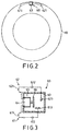
- Each of the resonant switching devices 60 is mounted inside a respective pneumatic tire 10 on a vehicle body 1.
- the excitation units 70 are mounted on the vehicle body 1 adjacent to the pneumatic tires 10, respectively.
- the controller 80 supplies an excitation signal to each of the excitation units 70, and monitors the output signals of the latter. By processing the output signals of the excitation units 70, the controller 80 is able to determine the pressure condition in each of the pneumatic tires 10 and generates a corresponding alarm output to alert the driver of the vehicle.
- each of the resonant switching devices 60 includes first and second resonant circuits 61, 62, each of which has a coil 611, 621 that functions as an inductor, and a capacitor 612, 622.
- the coils 611, 621 of the first and second resonant circuits 61, 62 are angularly displaced on the interior of the respective pneumatic tire 10.
- Each of the coils 611, 621 has a first end, and a second end connected to a first end of the corresponding capacitor 612, 622.
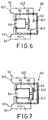
- Each of the resonant switching devices 60 further includes a casing 63 mounted inside the respective pneumatic tire 10.
- the casing 63 has one side formed with an opening 64.
- each capacitor 612, 622 is connected to a corresponding stationary electrical contact 613, 623 that is disposed in the casing 63.
- a movable electrical contact 66 which is connected to the first end of the coils 611, 621, is disposed in the casing 63 and is movable in the latter in response to the pressure of air that enters into the casing 63 via the opening 64.
- the movable electrical contact 66 is movable among an under-inflated switch position (see Figure 3), where the movable electrical contact 66 is not in contact with either of the stationary electrical contacts 613, 623 to disable both of the first and second resonant circuits 61, 62, a normal operating switch position (see Figure 6) , where the movable electrical contact 66 is in contact with the stationary electrical contact 613 so that the coil 611 and the capacitor 612 of the first resonant circuit 61 form a closed loop while the second resonant circuit 62 remains disabled, and an over-inflated switch position (see Figure 7), where the movable electrical contact 66 is in contact with both of the stationary electrical contacts 613, 623 so that the coils 611, 621 form closed loops with the capacitors 612, 622.
- an under-inflated switch position see Figure 3
- the movable electrical contact 66 is not in contact with either of the stationary electrical contacts 613, 623 to disable both of the first and second resonant circuits 61,
- a volume-variable member 65 such as a bellows tube, has an open end mounted on the casing 63 around the opening 64, and a closed end with the movable electrical contact 66 mounted thereon. Based on the pressure inside the respective pneumatic tire 10, the volume-variable member 65 expands to displace the movable electrical contact 66 linearly in the casing 63 to one of the under-inflated switch position, the normal operating switch position and the over-inflated switch position.
- connection between the first end of the coils 611, 621 and the movable electrical contact 66 can be achieved in many ways.
- both the casing 63 and the volume-variable member 65 can be made of a conductive material.
- the first ends of the coils 611, 621 can be connected directly to the conductive volume-variable member 65.
- the excitation units 70 are in the form of coils that function as inductors. When the pneumatic tires 10 rotate, each of the coils 611, 621 of the resonant switching devices 60 is moved to be proximate with the respective excitation unit 70 once every complete cycle of rotation of the respective pneumatic tire 10. Each of the resonant switching devices 60 co-acts with the respective excitation unit 70 by virtue of mutual inductance according to the impedance state of the resonant switching devices 60, e.g.
- the controller 80 monitors the output signals of the excitation units 70, the former is able to determine the pressure condition in each of the pneumatic tires 10 by detecting the frequency of change in the output signals of the excitation units 70.
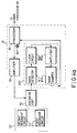
- the controller 80 is disposed in a passenger room (not shown) of the vehicle body 1 and includes a set of signal monitoring units 81 connected to the excitation units 70, respectively, a main processor 83 connected to the signal monitoring units 81, and an indicating device 84 connected to the main processor 83.
- the signal monitoring units 81 provide the excitation signal to the respective excitation unit 70 and monitor the output signal of the latter.
- Each signal monitoring unit 81 includes a signal detector 810, a processor 82, and an amplifier 85 connected to the respective excitation unit 70.
- the processor 82 is connected to a crystal oscillator 821, and is programmed so as to generate an oscillating signal that is amplified by the amplifier 85, thereby resulting in the excitation signal that is supplied to the respective excitation unit 70.
- the signal detector 810 is connected to the respective excitation unit 70 so as to receive the output signal of the latter.
- the signal detector 810 includes a wave detector 811, a filter circuit 812 for removing unwanted frequencies, an amplifier 813 and a wave shaper 814 connected to the processor 82.
- the output of the wave shaper 814 is in the form of pulse signals, each of which corresponds to a detected change in the output signal of the respective excitation unit 70 caused by mutual inductance between the excitation unit 70 and the respective resonant switching device 60, and is received by the processor 82.
- the processor 82 detects the frequency of the pulse signals received from the wave shaper 814 within a predetermined time period. Particularly, if the movable electrical contact 66 of one of the resonant switching devices 60 is in the under-inflated switch position (see Figure 3), no pulse signal is received by the corresponding processor 82 after one complete rotation of the respective pneumatic tire 10. If the movable electrical contact 66 of one of the resonant switching devices 60 is in the normal operating switch position (see Figure 6), one pulse signal is received by the corresponding processor 82 after one complete rotation of the respective pneumatic tire 10. If the movable electrical contact 66 of one of the resonant switching devices 60 is in the over-inflated switch position (see Figure 7), two pulse signals are received by the corresponding processor 82 after one complete rotation of the respective pneumatic tire 10.
- the processor 82 of each of the signal monitoring units 810 is connected to the main processor 83. Upon detection of an under-inflated or over-inflated tire condition, the processor 82 informs the main processor 83 of the same. At this time, the main processor 83 activates the indicating device 84 to inform the driver of the vehicle of the presence of an abnormal tire pressure condition.
- the indicating device 84 includes a display unit 841 that is controlled by the main processor 83 for visual identification of the pneumatic tire 10 with the abnormal pressure condition, and the pressure status of the identified abnormal pneumatic tire 10, and a sound generator 842 for alerting the driver of the vehicle of the presence of an abnormal tire pressure condition.
- FIG 8 illustrates a pressure-responsive resonant switching device 60a according to the second preferred embodiment of a pressure condition detecting apparatus of this invention.
- the resonant switching device 60a includes a resonant circuit 61a having a coil 611a that functions as an inductor, and a capacitor 612a.
- the coil 611a has a first end, and a second end connected to a first end of the capacitor 612a.
- the resonant switching device 60a further includes a casing 63 to be mounted inside a pneumatic tire.
- the casing 63 has one side formed with an opening 64.
- the second end of the capacitor 612a is connected to a stationary electrical contact 613a that is disposed in the casing 63.
- a movable electrical contact 66a which is connected to the first end of the coil 611a, is disposed in the casing 63 and is movable in the latter in response to the pressure of air that enters into the casing 63 via the opening 64.
- the movable electrical contact 66a is movable between a normal operating switch position, where the movable electrical contact 66a is in contact with the stationary electrical contact 613a so that the coil 611a and the capacitor 612a of the resonant circuit 61a form a closed loop, and an abnormal operating switch position, where the movable electrical contact 66a is not in contact with the stationary electrical contact 613a so that the resonant circuit 61a is disabled.
- a volume-variable member 65a such as a bellows tube, has an open end mounted on the casing 63 around the opening 64, and a closed end with the movable electrical contact 66a mounted thereon. Based on the pressure inside the pneumatic tire, the volume-variable member 65a expands to displace the movable electrical contact 66a linearly in the casing 63 to the normal operating switch position or the abnormal operating switch position.
- connection between the first end of the coil 611a and the movable electrical contact 66a is achieved in a manner similar to that of the previous embodiment and will not be detailed further.
- FIG. 9 illustrates a pressure-responsive resonant switching device 60b according to the third preferred embodiment of a pressure condition detecting apparatus of this invention.
- the resonant switching device 60b includes first and second resonant circuits 61, 62, like those of the first preferred embodiment.
- the resonant switching device 60b further includes a casing 63b mounted inside the pneumatic tire and having first and second guide tubes 631, 632, first and second stationary electrical contacts 613, 623 provided respectively in the first and second guide tubes 631, 632, a common electrical contact 633 extending into the first and second guide tubes 631, 632, and a movable electrical contact 66b having a pair of contact arms 661, 662 that extend respectively into the first and second guide tubes 631, 632.
- the movable electrical contact 66b further has a force bearing plate 663 that interconnects one end of the contact arms 661, 662 outside the casing 63b.
- a resilient cover 664 is mounted on one side of the casing 63b to cover the movable electrical contact 66b.
- the coil and the capacitor of the first and second resonant circuits 61, 62 are connected to the common electrical contact 633 and one of the stationary electrical contacts 613, 623, respectively.
- the movable electrical contact 66b is movable, in response to the pressure inside the pneumatic tire, among an under-inflated switch position, where the movable electrical contact 66b is not in contact with either of the stationary electrical contacts 613, 623, a normal operating switch position, where the contact arm 661 of the movable electrical contact 66b connects the common electrical contact 633 with the stationary electrical contact 613 to enable the first resonant circuit 61 to form a closed loop, and an over-inflated switch position, where the contact arms 661, 662 connect the common electrical contact 633 with the stationary electrical contacts 613, 623 to enable the first and second resonant circuits 61, 62 to form closed loops.
- Inner and outer springs 665, 666 bias the movable electrical contact 66b to the under-inflated switch position.
- Figure 10 illustrates a pressure - responsive resonant switching device 60c according to the fourth preferred embodiment of a pressure condition detecting apparatus of this invention.
- a spring-loaded piston device 65c is employed to displace the movable electrical contact 66 linearly in the casing 63 to one of the under-inflated switch position, the normal operating switch position, and the over-inflated switch position.
- the piston device 65c includes a tubular seat 651 on the casing 63 around the opening 64, a piston 652 disposed slidably in the tubular seat 651, a piston shaft 653 extending from one side of the piston 652 opposite to the opening 64 and extending out of the tubular seat 651 for mounting of the movable electrical contact 66 thereon, a spring 654 sleeved on the piston shaft 653 for biasing the piston 652 toward the opening 64, and a seal ring 655 around the piston shaft 653.
- the piston 652 moves in the tubular seat 651 against the action of the spring 654 in accordance with the pressure inside the pneumatic tire to result in corresponding movement of the movable electrical contact 66 together with the piston shaft 653 to one of the under-inflated switch position, the normal operating switch position and the over-inflated switch position.
- the pressure condition detecting apparatus has the following advantages: A pressure-responsive resonant switching device is used for each pneumatic tire. Since the need for wireless transmitters has been obviated, the apparatus of this invention is relatively inexpensive to implement, has a small and compact construction, and is less susceptible to improper operation. In addition, the various components of the apparatus are hidden when in use so as not to be easily subject to damage or theft.
Landscapes
- Engineering & Computer Science (AREA)
- Mechanical Engineering (AREA)
- Measuring Fluid Pressure (AREA)
Priority Applications (1)
| Application Number | Priority Date | Filing Date | Title |
|---|---|---|---|
| EP98300724A EP0933236A1 (de) | 1998-02-02 | 1998-02-02 | Vorrichtung zum Erkennen des Reifendruckzustandes |
Applications Claiming Priority (1)
| Application Number | Priority Date | Filing Date | Title |
|---|---|---|---|
| EP98300724A EP0933236A1 (de) | 1998-02-02 | 1998-02-02 | Vorrichtung zum Erkennen des Reifendruckzustandes |
Publications (1)
| Publication Number | Publication Date |
|---|---|
| EP0933236A1 true EP0933236A1 (de) | 1999-08-04 |
Family
ID=8234644
Family Applications (1)
| Application Number | Title | Priority Date | Filing Date |
|---|---|---|---|
| EP98300724A Withdrawn EP0933236A1 (de) | 1998-02-02 | 1998-02-02 | Vorrichtung zum Erkennen des Reifendruckzustandes |
Country Status (1)
| Country | Link |
|---|---|
| EP (1) | EP0933236A1 (de) |
Cited By (3)
| Publication number | Priority date | Publication date | Assignee | Title |
|---|---|---|---|---|
| US6822562B2 (en) | 2001-04-26 | 2004-11-23 | Siemens Vdo Automotive Corporation | Method of differentiating tires in a vehicle |
| US8151127B2 (en) | 2000-07-26 | 2012-04-03 | Bridgestone Americas Tire Operations, Llc | System for conserving battery life in a battery operated device |
| US8266465B2 (en) | 2000-07-26 | 2012-09-11 | Bridgestone Americas Tire Operation, LLC | System for conserving battery life in a battery operated device |
Citations (4)
| Publication number | Priority date | Publication date | Assignee | Title |
|---|---|---|---|---|
| US3662335A (en) * | 1969-10-08 | 1972-05-09 | Kurt Fritze | Device for road vehicles for the wireless transmission of at least one measured value of a rotating wheel to an indicating instrument |
| DE3209660A1 (de) * | 1982-03-17 | 1983-10-06 | Heinz Dieter Dipl Sonnleitner | Luftdruck-anzeigevorrichtung fuer fahrzeugreifen |
| US5035137A (en) * | 1987-07-16 | 1991-07-30 | Robert Bosch Gmbh | Tire pressure sensor for motor vehicles |
| US5289161A (en) | 1992-05-14 | 1994-02-22 | Huang Tien Tsai | Tire pressure indicator |
-
1998
- 1998-02-02 EP EP98300724A patent/EP0933236A1/de not_active Withdrawn
Patent Citations (4)
| Publication number | Priority date | Publication date | Assignee | Title |
|---|---|---|---|---|
| US3662335A (en) * | 1969-10-08 | 1972-05-09 | Kurt Fritze | Device for road vehicles for the wireless transmission of at least one measured value of a rotating wheel to an indicating instrument |
| DE3209660A1 (de) * | 1982-03-17 | 1983-10-06 | Heinz Dieter Dipl Sonnleitner | Luftdruck-anzeigevorrichtung fuer fahrzeugreifen |
| US5035137A (en) * | 1987-07-16 | 1991-07-30 | Robert Bosch Gmbh | Tire pressure sensor for motor vehicles |
| US5289161A (en) | 1992-05-14 | 1994-02-22 | Huang Tien Tsai | Tire pressure indicator |
Cited By (3)
| Publication number | Priority date | Publication date | Assignee | Title |
|---|---|---|---|---|
| US8151127B2 (en) | 2000-07-26 | 2012-04-03 | Bridgestone Americas Tire Operations, Llc | System for conserving battery life in a battery operated device |
| US8266465B2 (en) | 2000-07-26 | 2012-09-11 | Bridgestone Americas Tire Operation, LLC | System for conserving battery life in a battery operated device |
| US6822562B2 (en) | 2001-04-26 | 2004-11-23 | Siemens Vdo Automotive Corporation | Method of differentiating tires in a vehicle |
Similar Documents
| Publication | Publication Date | Title |
|---|---|---|
| JP3372503B2 (ja) | タイヤ圧検知システム | |
| US6604416B2 (en) | Tire monitoring transmitter with various operation modes | |
| US6058768A (en) | Apparatus for detecting pressure condition in a pneumatic tire | |
| EP1002670B1 (de) | Sender und externer Regler für ein Reifendrucküberwachungssystem | |
| US5540092A (en) | System and method for monitoring a pneumatic tire | |
| US5731516A (en) | System and method for monitoring a pneumatic tire | |
| US5798689A (en) | Tire pressure indicator | |
| US7212105B2 (en) | Transmitter for tire condition monitoring apparatus | |
| EP1026015A2 (de) | Reifendruck- Fernüberwachungssystem und Verfahren | |
| EP2368724A1 (de) | Reifenverschleisserkennungsvorrichtung | |
| JPH10239197A (ja) | タイヤ圧検知システム | |
| EP1327535A2 (de) | Reifendrucküberwachungssystem | |
| GB2069209A (en) | Abnormal tyre pressure detection systems | |
| JP2003175711A (ja) | タイヤ状態監視装置 | |
| US4072926A (en) | Tire pressure warning apparatus | |
| US4476455A (en) | Tire deflation warning device | |
| US6756892B2 (en) | Tire pressure sensing system | |
| EP0933236A1 (de) | Vorrichtung zum Erkennen des Reifendruckzustandes | |
| EP1270276A2 (de) | Reifenüberwachungsgerät | |
| JPH1178446A (ja) | タイヤ空気圧警報装置 | |
| JP2009216465A (ja) | タイヤ空気圧監視システム | |
| WO1996036861A1 (en) | Pressure sensing valve cap that permits the passage of air | |
| KR20030080569A (ko) | 자동차의 타이어 모니터 시스템 | |
| EP1580040B1 (de) | Sensorvorrichtung für einen reifen | |
| EP0108176A1 (de) | Feststellung eines Unterdruckzustandes eines Fahrzeugluftreifens |
Legal Events
| Date | Code | Title | Description |
|---|---|---|---|
| PUAI | Public reference made under article 153(3) epc to a published international application that has entered the european phase |
Free format text: ORIGINAL CODE: 0009012 |
|
| AK | Designated contracting states |
Kind code of ref document: A1 Designated state(s): AT BE CH DE DK ES FI FR GB GR IE IT LI LU MC NL PT SE |
|
| AX | Request for extension of the european patent |
Free format text: AL;LT;LV;MK;RO;SI |
|
| 17P | Request for examination filed |
Effective date: 20000201 |
|
| AKX | Designation fees paid |
Free format text: AT BE CH DE DK ES FI FR GB GR IE IT LI LU MC NL PT SE |
|
| AXX | Extension fees paid |
Free format text: AL PAYMENT 20000201;LT PAYMENT 20000201;LV PAYMENT 20000201;MK PAYMENT 20000201;RO PAYMENT 20000201;SI PAYMENT 20000201 |
|
| 17Q | First examination report despatched |
Effective date: 20020912 |
|
| STAA | Information on the status of an ep patent application or granted ep patent |
Free format text: STATUS: THE APPLICATION IS DEEMED TO BE WITHDRAWN |
|
| 18D | Application deemed to be withdrawn |
Effective date: 20030123 |