EP0933178A1 - Reinforced ceramic structures - Google Patents
Reinforced ceramic structures Download PDFInfo
- Publication number
- EP0933178A1 EP0933178A1 EP98204481A EP98204481A EP0933178A1 EP 0933178 A1 EP0933178 A1 EP 0933178A1 EP 98204481 A EP98204481 A EP 98204481A EP 98204481 A EP98204481 A EP 98204481A EP 0933178 A1 EP0933178 A1 EP 0933178A1
- Authority
- EP
- European Patent Office
- Prior art keywords
- rods
- die
- ceramic
- reinforced ceramic
- forming
- Prior art date
- Legal status (The legal status is an assumption and is not a legal conclusion. Google has not performed a legal analysis and makes no representation as to the accuracy of the status listed.)
- Granted
Links
- 239000011226 reinforced ceramic Substances 0.000 title claims abstract description 28
- 239000000919 ceramic Substances 0.000 claims abstract description 49
- 229910010293 ceramic material Inorganic materials 0.000 claims abstract description 27
- 238000000034 method Methods 0.000 claims abstract description 26
- 229910052751 metal Inorganic materials 0.000 claims abstract description 22
- 239000002184 metal Substances 0.000 claims abstract description 22
- VYPSYNLAJGMNEJ-UHFFFAOYSA-N Silicium dioxide Chemical compound O=[Si]=O VYPSYNLAJGMNEJ-UHFFFAOYSA-N 0.000 claims abstract description 21
- 239000000463 material Substances 0.000 claims abstract description 19
- 230000008569 process Effects 0.000 claims abstract description 18
- 238000005266 casting Methods 0.000 claims abstract description 16
- 238000004519 manufacturing process Methods 0.000 claims abstract description 16
- 230000003014 reinforcing effect Effects 0.000 claims abstract description 16
- XAGFODPZIPBFFR-UHFFFAOYSA-N aluminium Chemical compound [Al] XAGFODPZIPBFFR-UHFFFAOYSA-N 0.000 claims abstract description 10
- 229910052782 aluminium Inorganic materials 0.000 claims abstract description 9
- XFWJKVMFIVXPKK-UHFFFAOYSA-N calcium;oxido(oxo)alumane Chemical compound [Ca+2].[O-][Al]=O.[O-][Al]=O XFWJKVMFIVXPKK-UHFFFAOYSA-N 0.000 claims abstract description 8
- 229910052710 silicon Inorganic materials 0.000 claims abstract description 7
- 239000010703 silicon Substances 0.000 claims abstract description 7
- 239000000377 silicon dioxide Substances 0.000 claims abstract description 3
- 230000002093 peripheral effect Effects 0.000 claims description 8
- 238000001035 drying Methods 0.000 claims description 6
- 238000010304 firing Methods 0.000 claims description 5
- 238000010438 heat treatment Methods 0.000 claims description 5
- 238000011049 filling Methods 0.000 claims description 3
- 239000003795 chemical substances by application Substances 0.000 claims description 2
- 238000009499 grossing Methods 0.000 claims 1
- 239000011214 refractory ceramic Substances 0.000 claims 1
- KZHJGOXRZJKJNY-UHFFFAOYSA-N dioxosilane;oxo(oxoalumanyloxy)alumane Chemical compound O=[Si]=O.O=[Si]=O.O=[Al]O[Al]=O.O=[Al]O[Al]=O.O=[Al]O[Al]=O KZHJGOXRZJKJNY-UHFFFAOYSA-N 0.000 abstract description 4
- 229910052863 mullite Inorganic materials 0.000 abstract description 3
- 238000005242 forging Methods 0.000 description 18
- 239000010453 quartz Substances 0.000 description 11
- 239000000203 mixture Substances 0.000 description 7
- 230000035882 stress Effects 0.000 description 7
- PNEYBMLMFCGWSK-UHFFFAOYSA-N aluminium oxide Inorganic materials [O-2].[O-2].[O-2].[Al+3].[Al+3] PNEYBMLMFCGWSK-UHFFFAOYSA-N 0.000 description 6
- 239000004567 concrete Substances 0.000 description 6
- 239000000835 fiber Substances 0.000 description 6
- 239000004568 cement Substances 0.000 description 5
- 230000006872 improvement Effects 0.000 description 5
- 229910000831 Steel Inorganic materials 0.000 description 4
- RTAQQCXQSZGOHL-UHFFFAOYSA-N Titanium Chemical compound [Ti] RTAQQCXQSZGOHL-UHFFFAOYSA-N 0.000 description 4
- 230000008901 benefit Effects 0.000 description 4
- 238000005336 cracking Methods 0.000 description 4
- 238000001723 curing Methods 0.000 description 4
- 238000013461 design Methods 0.000 description 4
- 239000010959 steel Substances 0.000 description 4
- 229910000838 Al alloy Inorganic materials 0.000 description 3
- 229910001069 Ti alloy Inorganic materials 0.000 description 3
- 238000009792 diffusion process Methods 0.000 description 3
- 239000005350 fused silica glass Substances 0.000 description 3
- 239000012783 reinforcing fiber Substances 0.000 description 3
- 239000010935 stainless steel Substances 0.000 description 3
- 239000010936 titanium Substances 0.000 description 3
- 229910000851 Alloy steel Inorganic materials 0.000 description 2
- PXHVJJICTQNCMI-UHFFFAOYSA-N Nickel Chemical compound [Ni] PXHVJJICTQNCMI-UHFFFAOYSA-N 0.000 description 2
- 230000009172 bursting Effects 0.000 description 2
- 230000000295 complement effect Effects 0.000 description 2
- 239000002131 composite material Substances 0.000 description 2
- 230000006835 compression Effects 0.000 description 2
- 238000007906 compression Methods 0.000 description 2
- 238000003754 machining Methods 0.000 description 2
- 238000012986 modification Methods 0.000 description 2
- 230000004048 modification Effects 0.000 description 2
- 230000002787 reinforcement Effects 0.000 description 2
- 239000012779 reinforcing material Substances 0.000 description 2
- 238000007789 sealing Methods 0.000 description 2
- 230000035945 sensitivity Effects 0.000 description 2
- 229910001220 stainless steel Inorganic materials 0.000 description 2
- 238000012360 testing method Methods 0.000 description 2
- 229910052719 titanium Inorganic materials 0.000 description 2
- 229910052582 BN Inorganic materials 0.000 description 1
- PZNSFCLAULLKQX-UHFFFAOYSA-N Boron nitride Chemical compound N#B PZNSFCLAULLKQX-UHFFFAOYSA-N 0.000 description 1
- 229920000049 Carbon (fiber) Polymers 0.000 description 1
- 229910000990 Ni alloy Inorganic materials 0.000 description 1
- 239000000956 alloy Substances 0.000 description 1
- AZDRQVAHHNSJOQ-UHFFFAOYSA-N alumane Chemical group [AlH3] AZDRQVAHHNSJOQ-UHFFFAOYSA-N 0.000 description 1
- 238000013459 approach Methods 0.000 description 1
- 239000011324 bead Substances 0.000 description 1
- JUPQTSLXMOCDHR-UHFFFAOYSA-N benzene-1,4-diol;bis(4-fluorophenyl)methanone Chemical class OC1=CC=C(O)C=C1.C1=CC(F)=CC=C1C(=O)C1=CC=C(F)C=C1 JUPQTSLXMOCDHR-UHFFFAOYSA-N 0.000 description 1
- 238000005422 blasting Methods 0.000 description 1
- 239000004917 carbon fiber Substances 0.000 description 1
- 239000011248 coating agent Substances 0.000 description 1
- 238000000576 coating method Methods 0.000 description 1
- 150000001875 compounds Chemical class 0.000 description 1
- 238000007596 consolidation process Methods 0.000 description 1
- 238000010276 construction Methods 0.000 description 1
- 238000011109 contamination Methods 0.000 description 1
- ALEXXDVDDISNDU-JZYPGELDSA-N cortisol 21-acetate Chemical compound C1CC2=CC(=O)CC[C@]2(C)[C@@H]2[C@@H]1[C@@H]1CC[C@@](C(=O)COC(=O)C)(O)[C@@]1(C)C[C@@H]2O ALEXXDVDDISNDU-JZYPGELDSA-N 0.000 description 1
- 230000002939 deleterious effect Effects 0.000 description 1
- 230000001419 dependent effect Effects 0.000 description 1
- 238000004031 devitrification Methods 0.000 description 1
- 238000004512 die casting Methods 0.000 description 1
- 239000002360 explosive Substances 0.000 description 1
- 238000001125 extrusion Methods 0.000 description 1
- 239000011152 fibreglass Substances 0.000 description 1
- 229910021485 fumed silica Inorganic materials 0.000 description 1
- 230000006698 induction Effects 0.000 description 1
- 230000000977 initiatory effect Effects 0.000 description 1
- 238000011068 loading method Methods 0.000 description 1
- VNWKTOKETHGBQD-UHFFFAOYSA-N methane Chemical compound C VNWKTOKETHGBQD-UHFFFAOYSA-N 0.000 description 1
- 238000002156 mixing Methods 0.000 description 1
- 229910001120 nichrome Inorganic materials 0.000 description 1
- 229910052759 nickel Inorganic materials 0.000 description 1
- 229910052755 nonmetal Inorganic materials 0.000 description 1
- 230000000737 periodic effect Effects 0.000 description 1
- ISWSIDIOOBJBQZ-UHFFFAOYSA-N phenol group Chemical group C1(=CC=CC=C1)O ISWSIDIOOBJBQZ-UHFFFAOYSA-N 0.000 description 1
- 239000004033 plastic Substances 0.000 description 1
- 239000011120 plywood Substances 0.000 description 1
- 229920005989 resin Polymers 0.000 description 1
- 239000011347 resin Substances 0.000 description 1
- 230000035939 shock Effects 0.000 description 1
- 238000004513 sizing Methods 0.000 description 1
- 239000007787 solid Substances 0.000 description 1
- 229910000601 superalloy Inorganic materials 0.000 description 1
- 230000004083 survival effect Effects 0.000 description 1
- 230000008646 thermal stress Effects 0.000 description 1
- 238000012546 transfer Methods 0.000 description 1
- 239000002699 waste material Substances 0.000 description 1
- XLYOFNOQVPJJNP-UHFFFAOYSA-N water Substances O XLYOFNOQVPJJNP-UHFFFAOYSA-N 0.000 description 1
- 239000002023 wood Substances 0.000 description 1
Images


Classifications
-
- B—PERFORMING OPERATIONS; TRANSPORTING
- B21—MECHANICAL METAL-WORKING WITHOUT ESSENTIALLY REMOVING MATERIAL; PUNCHING METAL
- B21K—MAKING FORGED OR PRESSED METAL PRODUCTS, e.g. HORSE-SHOES, RIVETS, BOLTS OR WHEELS
- B21K5/00—Making tools or tool parts, e.g. pliers
- B21K5/20—Making working faces of dies, either recessed or outstanding
-
- B—PERFORMING OPERATIONS; TRANSPORTING
- B22—CASTING; POWDER METALLURGY
- B22D—CASTING OF METALS; CASTING OF OTHER SUBSTANCES BY THE SAME PROCESSES OR DEVICES
- B22D17/00—Pressure die casting or injection die casting, i.e. casting in which the metal is forced into a mould under high pressure
- B22D17/20—Accessories: Details
- B22D17/22—Dies; Die plates; Die supports; Cooling equipment for dies; Accessories for loosening and ejecting castings from dies
- B22D17/2209—Selection of die materials
-
- B—PERFORMING OPERATIONS; TRANSPORTING
- B28—WORKING CEMENT, CLAY, OR STONE
- B28B—SHAPING CLAY OR OTHER CERAMIC COMPOSITIONS; SHAPING SLAG; SHAPING MIXTURES CONTAINING CEMENTITIOUS MATERIAL, e.g. PLASTER
- B28B23/00—Arrangements specially adapted for the production of shaped articles with elements wholly or partly embedded in the moulding material; Production of reinforced objects
- B28B23/02—Arrangements specially adapted for the production of shaped articles with elements wholly or partly embedded in the moulding material; Production of reinforced objects wherein the elements are reinforcing members
-
- C—CHEMISTRY; METALLURGY
- C04—CEMENTS; CONCRETE; ARTIFICIAL STONE; CERAMICS; REFRACTORIES
- C04B—LIME, MAGNESIA; SLAG; CEMENTS; COMPOSITIONS THEREOF, e.g. MORTARS, CONCRETE OR LIKE BUILDING MATERIALS; ARTIFICIAL STONE; CERAMICS; REFRACTORIES; TREATMENT OF NATURAL STONE
- C04B28/00—Compositions of mortars, concrete or artificial stone, containing inorganic binders or the reaction product of an inorganic and an organic binder, e.g. polycarboxylate cements
- C04B28/02—Compositions of mortars, concrete or artificial stone, containing inorganic binders or the reaction product of an inorganic and an organic binder, e.g. polycarboxylate cements containing hydraulic cements other than calcium sulfates
- C04B28/06—Aluminous cements
-
- C—CHEMISTRY; METALLURGY
- C04—CEMENTS; CONCRETE; ARTIFICIAL STONE; CERAMICS; REFRACTORIES
- C04B—LIME, MAGNESIA; SLAG; CEMENTS; COMPOSITIONS THEREOF, e.g. MORTARS, CONCRETE OR LIKE BUILDING MATERIALS; ARTIFICIAL STONE; CERAMICS; REFRACTORIES; TREATMENT OF NATURAL STONE
- C04B32/00—Artificial stone not provided for in other groups of this subclass
- C04B32/02—Artificial stone not provided for in other groups of this subclass with reinforcements
-
- C—CHEMISTRY; METALLURGY
- C04—CEMENTS; CONCRETE; ARTIFICIAL STONE; CERAMICS; REFRACTORIES
- C04B—LIME, MAGNESIA; SLAG; CEMENTS; COMPOSITIONS THEREOF, e.g. MORTARS, CONCRETE OR LIKE BUILDING MATERIALS; ARTIFICIAL STONE; CERAMICS; REFRACTORIES; TREATMENT OF NATURAL STONE
- C04B35/00—Shaped ceramic products characterised by their composition; Ceramics compositions; Processing powders of inorganic compounds preparatory to the manufacturing of ceramic products
- C04B35/622—Forming processes; Processing powders of inorganic compounds preparatory to the manufacturing of ceramic products
- C04B35/626—Preparing or treating the powders individually or as batches ; preparing or treating macroscopic reinforcing agents for ceramic products, e.g. fibres; mechanical aspects section B
- C04B35/62605—Treating the starting powders individually or as mixtures
- C04B35/62645—Thermal treatment of powders or mixtures thereof other than sintering
- C04B35/62665—Flame, plasma or melting treatment
-
- C—CHEMISTRY; METALLURGY
- C04—CEMENTS; CONCRETE; ARTIFICIAL STONE; CERAMICS; REFRACTORIES
- C04B—LIME, MAGNESIA; SLAG; CEMENTS; COMPOSITIONS THEREOF, e.g. MORTARS, CONCRETE OR LIKE BUILDING MATERIALS; ARTIFICIAL STONE; CERAMICS; REFRACTORIES; TREATMENT OF NATURAL STONE
- C04B35/00—Shaped ceramic products characterised by their composition; Ceramics compositions; Processing powders of inorganic compounds preparatory to the manufacturing of ceramic products
- C04B35/622—Forming processes; Processing powders of inorganic compounds preparatory to the manufacturing of ceramic products
- C04B35/626—Preparing or treating the powders individually or as batches ; preparing or treating macroscopic reinforcing agents for ceramic products, e.g. fibres; mechanical aspects section B
- C04B35/628—Coating the powders or the macroscopic reinforcing agents
- C04B35/62844—Coating fibres
-
- C—CHEMISTRY; METALLURGY
- C04—CEMENTS; CONCRETE; ARTIFICIAL STONE; CERAMICS; REFRACTORIES
- C04B—LIME, MAGNESIA; SLAG; CEMENTS; COMPOSITIONS THEREOF, e.g. MORTARS, CONCRETE OR LIKE BUILDING MATERIALS; ARTIFICIAL STONE; CERAMICS; REFRACTORIES; TREATMENT OF NATURAL STONE
- C04B35/00—Shaped ceramic products characterised by their composition; Ceramics compositions; Processing powders of inorganic compounds preparatory to the manufacturing of ceramic products
- C04B35/622—Forming processes; Processing powders of inorganic compounds preparatory to the manufacturing of ceramic products
- C04B35/626—Preparing or treating the powders individually or as batches ; preparing or treating macroscopic reinforcing agents for ceramic products, e.g. fibres; mechanical aspects section B
- C04B35/63—Preparing or treating the powders individually or as batches ; preparing or treating macroscopic reinforcing agents for ceramic products, e.g. fibres; mechanical aspects section B using additives specially adapted for forming the products, e.g.. binder binders
- C04B35/6303—Inorganic additives
-
- C—CHEMISTRY; METALLURGY
- C04—CEMENTS; CONCRETE; ARTIFICIAL STONE; CERAMICS; REFRACTORIES
- C04B—LIME, MAGNESIA; SLAG; CEMENTS; COMPOSITIONS THEREOF, e.g. MORTARS, CONCRETE OR LIKE BUILDING MATERIALS; ARTIFICIAL STONE; CERAMICS; REFRACTORIES; TREATMENT OF NATURAL STONE
- C04B35/00—Shaped ceramic products characterised by their composition; Ceramics compositions; Processing powders of inorganic compounds preparatory to the manufacturing of ceramic products
- C04B35/71—Ceramic products containing macroscopic reinforcing agents
- C04B35/78—Ceramic products containing macroscopic reinforcing agents containing non-metallic materials
- C04B35/80—Fibres, filaments, whiskers, platelets, or the like
-
- C—CHEMISTRY; METALLURGY
- C04—CEMENTS; CONCRETE; ARTIFICIAL STONE; CERAMICS; REFRACTORIES
- C04B—LIME, MAGNESIA; SLAG; CEMENTS; COMPOSITIONS THEREOF, e.g. MORTARS, CONCRETE OR LIKE BUILDING MATERIALS; ARTIFICIAL STONE; CERAMICS; REFRACTORIES; TREATMENT OF NATURAL STONE
- C04B2235/00—Aspects relating to ceramic starting mixtures or sintered ceramic products
- C04B2235/02—Composition of constituents of the starting material or of secondary phases of the final product
- C04B2235/30—Constituents and secondary phases not being of a fibrous nature
- C04B2235/32—Metal oxides, mixed metal oxides, or oxide-forming salts thereof, e.g. carbonates, nitrates, (oxy)hydroxides, chlorides
- C04B2235/3205—Alkaline earth oxides or oxide forming salts thereof, e.g. beryllium oxide
- C04B2235/3208—Calcium oxide or oxide-forming salts thereof, e.g. lime
-
- C—CHEMISTRY; METALLURGY
- C04—CEMENTS; CONCRETE; ARTIFICIAL STONE; CERAMICS; REFRACTORIES
- C04B—LIME, MAGNESIA; SLAG; CEMENTS; COMPOSITIONS THEREOF, e.g. MORTARS, CONCRETE OR LIKE BUILDING MATERIALS; ARTIFICIAL STONE; CERAMICS; REFRACTORIES; TREATMENT OF NATURAL STONE
- C04B2235/00—Aspects relating to ceramic starting mixtures or sintered ceramic products
- C04B2235/02—Composition of constituents of the starting material or of secondary phases of the final product
- C04B2235/30—Constituents and secondary phases not being of a fibrous nature
- C04B2235/32—Metal oxides, mixed metal oxides, or oxide-forming salts thereof, e.g. carbonates, nitrates, (oxy)hydroxides, chlorides
- C04B2235/3217—Aluminum oxide or oxide forming salts thereof, e.g. bauxite, alpha-alumina
- C04B2235/3222—Aluminates other than alumino-silicates, e.g. spinel (MgAl2O4)
-
- C—CHEMISTRY; METALLURGY
- C04—CEMENTS; CONCRETE; ARTIFICIAL STONE; CERAMICS; REFRACTORIES
- C04B—LIME, MAGNESIA; SLAG; CEMENTS; COMPOSITIONS THEREOF, e.g. MORTARS, CONCRETE OR LIKE BUILDING MATERIALS; ARTIFICIAL STONE; CERAMICS; REFRACTORIES; TREATMENT OF NATURAL STONE
- C04B2235/00—Aspects relating to ceramic starting mixtures or sintered ceramic products
- C04B2235/02—Composition of constituents of the starting material or of secondary phases of the final product
- C04B2235/50—Constituents or additives of the starting mixture chosen for their shape or used because of their shape or their physical appearance
- C04B2235/52—Constituents or additives characterised by their shapes
- C04B2235/5208—Fibers
- C04B2235/5216—Inorganic
- C04B2235/522—Oxidic
- C04B2235/5224—Alumina or aluminates
-
- C—CHEMISTRY; METALLURGY
- C04—CEMENTS; CONCRETE; ARTIFICIAL STONE; CERAMICS; REFRACTORIES
- C04B—LIME, MAGNESIA; SLAG; CEMENTS; COMPOSITIONS THEREOF, e.g. MORTARS, CONCRETE OR LIKE BUILDING MATERIALS; ARTIFICIAL STONE; CERAMICS; REFRACTORIES; TREATMENT OF NATURAL STONE
- C04B2235/00—Aspects relating to ceramic starting mixtures or sintered ceramic products
- C04B2235/02—Composition of constituents of the starting material or of secondary phases of the final product
- C04B2235/50—Constituents or additives of the starting mixture chosen for their shape or used because of their shape or their physical appearance
- C04B2235/52—Constituents or additives characterised by their shapes
- C04B2235/5208—Fibers
- C04B2235/5216—Inorganic
- C04B2235/522—Oxidic
- C04B2235/5232—Silica or silicates other than aluminosilicates, e.g. quartz
-
- C—CHEMISTRY; METALLURGY
- C04—CEMENTS; CONCRETE; ARTIFICIAL STONE; CERAMICS; REFRACTORIES
- C04B—LIME, MAGNESIA; SLAG; CEMENTS; COMPOSITIONS THEREOF, e.g. MORTARS, CONCRETE OR LIKE BUILDING MATERIALS; ARTIFICIAL STONE; CERAMICS; REFRACTORIES; TREATMENT OF NATURAL STONE
- C04B2235/00—Aspects relating to ceramic starting mixtures or sintered ceramic products
- C04B2235/02—Composition of constituents of the starting material or of secondary phases of the final product
- C04B2235/50—Constituents or additives of the starting mixture chosen for their shape or used because of their shape or their physical appearance
- C04B2235/52—Constituents or additives characterised by their shapes
- C04B2235/5208—Fibers
- C04B2235/5264—Fibers characterised by the diameter of the fibers
-
- C—CHEMISTRY; METALLURGY
- C04—CEMENTS; CONCRETE; ARTIFICIAL STONE; CERAMICS; REFRACTORIES
- C04B—LIME, MAGNESIA; SLAG; CEMENTS; COMPOSITIONS THEREOF, e.g. MORTARS, CONCRETE OR LIKE BUILDING MATERIALS; ARTIFICIAL STONE; CERAMICS; REFRACTORIES; TREATMENT OF NATURAL STONE
- C04B2235/00—Aspects relating to ceramic starting mixtures or sintered ceramic products
- C04B2235/02—Composition of constituents of the starting material or of secondary phases of the final product
- C04B2235/50—Constituents or additives of the starting mixture chosen for their shape or used because of their shape or their physical appearance
- C04B2235/52—Constituents or additives characterised by their shapes
- C04B2235/5208—Fibers
- C04B2235/5268—Orientation of the fibers
-
- C—CHEMISTRY; METALLURGY
- C04—CEMENTS; CONCRETE; ARTIFICIAL STONE; CERAMICS; REFRACTORIES
- C04B—LIME, MAGNESIA; SLAG; CEMENTS; COMPOSITIONS THEREOF, e.g. MORTARS, CONCRETE OR LIKE BUILDING MATERIALS; ARTIFICIAL STONE; CERAMICS; REFRACTORIES; TREATMENT OF NATURAL STONE
- C04B2235/00—Aspects relating to ceramic starting mixtures or sintered ceramic products
- C04B2235/02—Composition of constituents of the starting material or of secondary phases of the final product
- C04B2235/50—Constituents or additives of the starting mixture chosen for their shape or used because of their shape or their physical appearance
- C04B2235/52—Constituents or additives characterised by their shapes
- C04B2235/5284—Hollow fibers, e.g. nanotubes
-
- C—CHEMISTRY; METALLURGY
- C04—CEMENTS; CONCRETE; ARTIFICIAL STONE; CERAMICS; REFRACTORIES
- C04B—LIME, MAGNESIA; SLAG; CEMENTS; COMPOSITIONS THEREOF, e.g. MORTARS, CONCRETE OR LIKE BUILDING MATERIALS; ARTIFICIAL STONE; CERAMICS; REFRACTORIES; TREATMENT OF NATURAL STONE
- C04B2235/00—Aspects relating to ceramic starting mixtures or sintered ceramic products
- C04B2235/70—Aspects relating to sintered or melt-casted ceramic products
- C04B2235/94—Products characterised by their shape
- C04B2235/945—Products containing grooves, cuts, recesses or protusions
-
- C—CHEMISTRY; METALLURGY
- C04—CEMENTS; CONCRETE; ARTIFICIAL STONE; CERAMICS; REFRACTORIES
- C04B—LIME, MAGNESIA; SLAG; CEMENTS; COMPOSITIONS THEREOF, e.g. MORTARS, CONCRETE OR LIKE BUILDING MATERIALS; ARTIFICIAL STONE; CERAMICS; REFRACTORIES; TREATMENT OF NATURAL STONE
- C04B2235/00—Aspects relating to ceramic starting mixtures or sintered ceramic products
- C04B2235/70—Aspects relating to sintered or melt-casted ceramic products
- C04B2235/96—Properties of ceramic products, e.g. mechanical properties such as strength, toughness, wear resistance
- C04B2235/9607—Thermal properties, e.g. thermal expansion coefficient
-
- Y—GENERAL TAGGING OF NEW TECHNOLOGICAL DEVELOPMENTS; GENERAL TAGGING OF CROSS-SECTIONAL TECHNOLOGIES SPANNING OVER SEVERAL SECTIONS OF THE IPC; TECHNICAL SUBJECTS COVERED BY FORMER USPC CROSS-REFERENCE ART COLLECTIONS [XRACs] AND DIGESTS
- Y10—TECHNICAL SUBJECTS COVERED BY FORMER USPC
- Y10T—TECHNICAL SUBJECTS COVERED BY FORMER US CLASSIFICATION
- Y10T428/00—Stock material or miscellaneous articles
- Y10T428/25—Web or sheet containing structurally defined element or component and including a second component containing structurally defined particles
- Y10T428/252—Glass or ceramic [i.e., fired or glazed clay, cement, etc.] [porcelain, quartz, etc.]
-
- Y—GENERAL TAGGING OF NEW TECHNOLOGICAL DEVELOPMENTS; GENERAL TAGGING OF CROSS-SECTIONAL TECHNOLOGIES SPANNING OVER SEVERAL SECTIONS OF THE IPC; TECHNICAL SUBJECTS COVERED BY FORMER USPC CROSS-REFERENCE ART COLLECTIONS [XRACs] AND DIGESTS
- Y10—TECHNICAL SUBJECTS COVERED BY FORMER USPC
- Y10T—TECHNICAL SUBJECTS COVERED BY FORMER US CLASSIFICATION
- Y10T428/00—Stock material or miscellaneous articles
- Y10T428/25—Web or sheet containing structurally defined element or component and including a second component containing structurally defined particles
- Y10T428/256—Heavy metal or aluminum or compound thereof
-
- Y—GENERAL TAGGING OF NEW TECHNOLOGICAL DEVELOPMENTS; GENERAL TAGGING OF CROSS-SECTIONAL TECHNOLOGIES SPANNING OVER SEVERAL SECTIONS OF THE IPC; TECHNICAL SUBJECTS COVERED BY FORMER USPC CROSS-REFERENCE ART COLLECTIONS [XRACs] AND DIGESTS
- Y10—TECHNICAL SUBJECTS COVERED BY FORMER USPC
- Y10T—TECHNICAL SUBJECTS COVERED BY FORMER US CLASSIFICATION
- Y10T428/00—Stock material or miscellaneous articles
- Y10T428/26—Web or sheet containing structurally defined element or component, the element or component having a specified physical dimension
-
- Y—GENERAL TAGGING OF NEW TECHNOLOGICAL DEVELOPMENTS; GENERAL TAGGING OF CROSS-SECTIONAL TECHNOLOGIES SPANNING OVER SEVERAL SECTIONS OF THE IPC; TECHNICAL SUBJECTS COVERED BY FORMER USPC CROSS-REFERENCE ART COLLECTIONS [XRACs] AND DIGESTS
- Y10—TECHNICAL SUBJECTS COVERED BY FORMER USPC
- Y10T—TECHNICAL SUBJECTS COVERED BY FORMER US CLASSIFICATION
- Y10T428/00—Stock material or miscellaneous articles
- Y10T428/29—Coated or structually defined flake, particle, cell, strand, strand portion, rod, filament, macroscopic fiber or mass thereof
- Y10T428/2913—Rod, strand, filament or fiber
- Y10T428/298—Physical dimension
-
- Y—GENERAL TAGGING OF NEW TECHNOLOGICAL DEVELOPMENTS; GENERAL TAGGING OF CROSS-SECTIONAL TECHNOLOGIES SPANNING OVER SEVERAL SECTIONS OF THE IPC; TECHNICAL SUBJECTS COVERED BY FORMER USPC CROSS-REFERENCE ART COLLECTIONS [XRACs] AND DIGESTS
- Y10—TECHNICAL SUBJECTS COVERED BY FORMER USPC
- Y10T—TECHNICAL SUBJECTS COVERED BY FORMER US CLASSIFICATION
- Y10T428/00—Stock material or miscellaneous articles
- Y10T428/29—Coated or structually defined flake, particle, cell, strand, strand portion, rod, filament, macroscopic fiber or mass thereof
- Y10T428/2982—Particulate matter [e.g., sphere, flake, etc.]
- Y10T428/2991—Coated
- Y10T428/2993—Silicic or refractory material containing [e.g., tungsten oxide, glass, cement, etc.]
- Y10T428/2995—Silane, siloxane or silicone coating
Definitions
- This invention pertains to reinforcement of ceramic structures subject to thermal and/or mechanical stress, and to a method of manufacturing a reinforced ceramic structur with reinforcing elements that are chemically and thermally compatible with the ceramic material. More particularly, this invention pertains to reinforcement of ceramic dies used for forging or for superplastic forming and diffusion bonding of aluminum and titanium alloys and other materials that can be formed at elevated temperature.
- Castable ceramic materials made of fused silica-aggregate and calcium aluminate cement are widely used in many high temperature (1000°F-1700°F) environments because of their low cost and their properties of compression strength, hardness, heat resistance, dimensional stability and rapid castability to net shape.
- their use has been limited because of their low modulus of rupture and brittleness, which historically has lead to failures due to cracking.
- Other stronger castable ceramics, such as mullite based materials are being developed, but these materials are also relatively weak and brittle and have their own drawbacks, such as excessive shrinkage during drying and curing. All of these materials would be more useful if a way were found to increase their load bearing capacity.
- External compressive support is a common stratagem and in fact was first used in the form of a steel containment box as a safety precaution because of the fear of explosive bursting of the ceramic die under high forming gas pressure and high compressive loading by the press on the lid to seal the pressurized forming gas in the die cavity.
- Steel containment boxes continue to be used despite the proven safety of freestanding ceramic dies.
- reinforcing fibers mixed into the castable ceramic material when it is mixed up for casting is a concept that has been explored by numerous ceramic investigators.
- the material of which the reinforcing fibers is made has high tensile strength and the theory behind this approach is that the tensile load would transfer to and be borne by the fibers, thereby improving the modulus of rupture and tensile strength.
- Experience with reinforcing fibers in ceramics is encouraging: although there has not been a significant increase in the modulus of rupture, there has been some improvement in toughness.
- the large difference in coefficient of thermal expansion between the CRES fiber and the ceramic material can produce internal stresses within the die that can be deleterious to its survival in a hot, high stress application.
- this invention provides an improved reinforced ceramic structure having a modulus of rupture that is substantially greater than that provided by the same structure design without the inventive reinforcing.
- the invention also provides an improved method of reinforcing ceramic structures that is relatively inexpensive, easy to use in a production environment and repeatably produces a substantial improvement in the load bearing capacity of the ceramic structure.
- a reinforced ceramic structure such as a superplastic forming die or a forging die having a body of cast ceramic material in which are embedded an array of ceramic rods of a high temperature resistant material such as quartz or alumina having a flexural strength at least five times greater than the ceramic material, and a coefficient of thermal expansion substantially equal to the coefficient of thermal expansion of the cast ceramic material.
- the rods are preferably solid and cylindrical, about 3 ⁇ 4" in diameter and extend through the full length and width of the cast ceramic body in an orthogonal grid positioned in the body in the region where failure initiates in the absence of the reinforcing rods.
- the invention will be described first as embodied in a ceramic die for superplastic forming and diffusion bonding of metal parts, primarily titanium alloys and aluminum alloys. Nickel based alloys and stainless steel can also be superplastically formed in ceramic dies. Free standing ceramic dies for this purpose are described in U.S. Patent No. 5,467,626, the disclosure of which is incorporated herein by reference. Use of the reinforcing process disclosed herein improves the load bearing capacity of these dies, slows the crack initiation and propagation process, and increases the number of parts that can be made on them before they fail. However, this invention is not limited to use in ceramic dies.
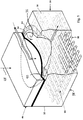
- a ceramic die 30 having a die base 32 including a die cavity 34 with the part shape defined by internal surfaces 36 of the die cavity 34.
- a peripheral lip 40 at the top of the wall has sealing structure such as a bead or a groove which could receive a heat resistant gasket such as a stainless steel ring 44 by which the die cavity 34 can be sealed by a lid 46 held in place on the peripheral lip by strong compressive force (represented by arrow 48) exerted by hydraulic hot forming or a superplastic forming press (not shown) of known design and available commercially from sources such as L&F Press Company, Inc. in Huntington Park, California.
- the reinforced ceramic superelastic forming die shown in Fig. 1 has a plurality of quartz rods 50 disposed in an array in the floor 38 of the die base 32.
- the rods 50 are 3 ⁇ 4" in diameter and are spaced apart in two or more rows disposed orthogonally to each other and parallel to the plane of the under surface of the die floor 38.
- the rods 50 in each row are spaced apart a distance equal to about 1-5 times the rod diameter and the rows are spaced apart a distance equal to about 1 ⁇ 2-3 times the rod diameter.
- the rods 50 are available from several suppliers, including G.E and McMaster-Carr and are used as received from the manufacturer.
- the quartz rods bond strongly to the calcium aluminate cement without the need for texturing or profiling the rods.
- the rods may textured, as by grit blasting, and/or profiled by machining to produce surface profiles to improve the bonding strength and securely lock the rods longitudinally in the ceramic die base 32.
- quartz is a notch sensitive material, so it may be preferable to avoid sharp comers in profiled designs to increase rod resistance to cracking or failure.
- the shrinkage rate of the particular ceramic material used for the die or other structure during the drying or firing steps is more than about 1%, there may be a benefit to allow relative movement between the ceramic material and the rods 50 during shrinkage.
- the rods can be waxed or otherwise treated with a parting agent to prevent bonding between the rods and the ceramic material.
- the rods When the rods are bonded and/or locked in the ceramic die base 32 by profiling the rods, they contribute stiffness and also tensile strength to the ceramic body. When the rods are unbonded and unlocked in the ceramic body 32, that is, they can move longitudinally relative to the ceramic body 32, they contribute only stiffness. However, the stiffness contribution alone is substantial.
- Construction of the die base 32 utilizes a die casting box 55, which is conveniently made of 3 ⁇ 4 plywood or oriented strand board.
- a model 56 of the part is attached to the floor of the box 55 and two or more rows of aligned holes 57 and 59 are drilled adjacent to the top edge of the box 55 for rows of rods 50.
- the holes 57 and 59 extend completely through the sides of the box 55 so they can be slid into the holes 57 and 59.
- quartz rods it is advisable to avoid contaminating them by handling with bare hands since they are susceptible to devitrification at high temperatures if contaminated during handling.
- the rods 50 can be held in position by wood strips tacked over the rows of holes alter the rods 50 have been inserted, and/or the holes may be plugged and sealed by an appropriate sealing compound, such as Hydro-Cal cement.
- the preferred concrete mixture is a fumed silica/calcium-aluminate composition such as castable Thermo-Sil 220 from Ceradyne Thermo-Materials Corp. or HS2 Castable Ceramic from Pyromedia Inc. in Seattle, WA. Casting procedures can be obtained from the manufacturer and from the aforesaid U.S. Patent No. 5,467,626.
- the box 55 is inverted so the model 56 is on the top.
- the box 55 is dismantled and a crane or winch is attached to the model 56 to gradually apply upward tension on the model 56 until it breaks free from the green die 34.
- the casting is then covered with wet cloths and allowed to cure at room temperature (60°-80°F) for 3-7 days, depending on its size, removing the wet cloths after 1-2 days.
- the green die is heated in a hot air dryer to 150°F at a ramp rate of about 50°F in 16-36 hours, depending on its size, and dried for 2-5 days or more, depending on its size, at 150°F.
- Quartz rods have a flexural strength of about 10,000 psi which provides substantial stiffness to the die base 32.
- the maximum modulus of rupture that can be achieved in an un-reinforced silica and calcium-aluminate cement composition is about 1500 psi, and that performance is degraded by temperatures in the superplastic forming range of titanium which is about 1650 °F because water in the hydraulic bond is driven off at that temperature.
- the improvement in the modulus of rupture of the dies reinforced with quartz rods 50 is significant.
- Test samples have shown a 245% increase in strength, although strength of a complex structure such as a die is often dependent on many factors, including drying, curing and firing procedures and rod placement, so it is difficult to translate strength improvement in test samples to strength improvement in the final structure such as a die.
- Ceramic materials such as alumina, that are stronger than quartz and do not suffer from its notch sensitivity and contamination sensitivity.
- Alumina rods are available with a flexural strength of about 56,000 psi from Coors in Golden, Colorado, but the cost is significantly greater. The trade-off between increased cost and increased strength must be determined for each application.
- reinforcing rods 50 of ceramic material such as fused oxides of silicon or aluminum (quartz or alumina). It can be determined by finite element analysis, conventional stress analysis, and/or practical experience where the structures need reinforcing and the rods can be cast into the lid and side walls as required to obtain maximum performance, using the procedures set forth above.
- the reinforcing fused silica rods 50 were selected for use in fused silica/calcium aluminate material because of the close match of coefficients of thermal expansion.
- newer castable ceramic materials with a greater modulus of rupture are becoming available, such as Mullite aggregate ceramics, available as CK-1081 from Norton Company Refractory Systems. This material has a somewhat greater shrinkage rate and coefficient of thermal expansion than that of the in fused silica/calcium aluminate material, but is compatible chemically and thermally with alumina rods.
- the invention can be used to produce reinforced dies for making isostatically pressed metal or non-metal parts, such as "PEEK” composites or APC II type resins with carbon fiber in a thermal process using a low temperature superplastic aluminum driver sheet to form the metal sheet or form and consolidate the composite between the driver sheet and the form or an interposed aluminum base sheet in accordance with U.S. Patent No. .4,644,626.
- the rapid and inexpensive production of ceramic forming dies for this application would reduce the cost and speed the production of parts formed with this process.
- a matched set of reinforced ceramic forging dies including an upper die 70 and a lower die 75, shown in Fig. 3 is used to make an aluminum part 80 shown in Fig. 4, using the closed-die forging process.
- This is a flashless process that does not require the creation of a flash around the periphery of the die to achieve complete die filling.
- the accuracy of the casting process makes it possible to achieve the die design and work piece volume in the die set so that complete die filling can be achieved without excessive pressure because of overfilling the work piece volume.
- the lower die 75 has a die cavity 85 with a surface profile like the desired surface profile of the underside of the desired part 80
- the upper die has a corresponding male punch member 90 having a surface profile like the upper surface of the desired part 80.
- the forging dies are mounted in a forging press in the conventional manner and are heated to the forging temperature for the metal of which the part 80 is to be made.
- a metal blank is placed in the press between the two dies 70 and 75 and is allowed to reach forging temperature.
- greater throughput can be achieved by preheating the metal blank to forging temperature before placing it in the press.
- the press When the blank has reached forging temperature, the press is operated to bring the dies 70 and 75 against the blank and form it to the shape defined by the surfaces of the upper and lower forming surfaces. This is an isothermal process in which forming occurs at a slow speed, so that minimal force is required and significant part complexity can be obtained.
- the dies 70 and 75 are each made using the same process described above for the superplastic forming die 30, but a greater number of reinforcing rods 50 are used to strengthen the structure.
- the part 80 made on the dies set 70/75 is significantly stronger than a corresponding part made by conventional machining would be because the grain flow in the part 80 is oriented to follow the contour of the part 80, so the greatest strength is provided in the direction of the greatest stress that the part experiences in use.
- FIG. 5 Another set of forging dies made in accordance with this invention, shown in Fig. 5, includes an upper die 94 and a lower die 96 for making a part 100 shown in Fig. 6.
- the upper die 94 has cavities 102 and 104 for producing complementary shapes 106 and 108 on the top surface of the part 100.
- the lower die 96 has a cavity 110 for producing the complementary shape 112 on the underside of the part 100.
- the forging process used with the die set 94/96 produces flow of the metal blank material into the cavities 102, 104 and 110 by extrusion.
- the dies 94 and 96 are made using the same process as the process used to make the superplastic forming die 30 and the forging dies 70 and 75. Reinforcing rods 50 are placed in the mold orthogonally oriented in rows as shown in Fig. 5. A preheated metal blank is inserted in the press between the dies 94 and 96 and the dies are moved toward each other against the metal blank. The hot metal in the blank flows slowly under pressure exerted by the faces of the dies 94 and 96 to fill the cavities 102, 104 and 110 and the space between the die faces to produce the part 100.
- the improved strength that the reinforcing rods 50 provide to the dies 94 and 96 enable them to survive the flexural and bursting loads that forging dies experience in use and also to resist chipping and cracking in use for improved durability, so that they can produce a greater number of parts at a lower total cost.
Abstract
Description
- This invention pertains to reinforcement of ceramic structures subject to thermal and/or mechanical stress, and to a method of manufacturing a reinforced ceramic structur with reinforcing elements that are chemically and thermally compatible with the ceramic material. More particularly, this invention pertains to reinforcement of ceramic dies used for forging or for superplastic forming and diffusion bonding of aluminum and titanium alloys and other materials that can be formed at elevated temperature.
- Castable ceramic materials made of fused silica-aggregate and calcium aluminate cement are widely used in many high temperature (1000°F-1700°F) environments because of their low cost and their properties of compression strength, hardness, heat resistance, dimensional stability and rapid castability to net shape. However, their use has been limited because of their low modulus of rupture and brittleness, which historically has lead to failures due to cracking. Other stronger castable ceramics, such as mullite based materials are being developed, but these materials are also relatively weak and brittle and have their own drawbacks, such as excessive shrinkage during drying and curing. All of these materials would be more useful if a way were found to increase their load bearing capacity.
- One valuable application for ceramic materials has been in forming dies for superplastic forming, primarily of titanium and aluminum alloys, but also some corrosion resistant steel alloys, nickel alloys and superalloys. The desirable properties of low cost, rapid production and excellent high temperature stability make possible the fast, accurate and low cost production of dies using castable ceramic materials. Patent No. 5, 467,626 issued on June 4, 1996 to D.G. Sanders teaches an innovative freestanding ceramic die made with these materials. The disclosure of this patent is incorporated herein by reference.
- However, the durability of ceramic dies is poor. It is uncommon for a die for a part of average draw depth to produce 20 parts before it fails and must be replaced, so ceramic dies are used primarily for rapid prototyping and limited production quantities of parts. Durability can be increased by increasing the thickness of the die, but excessive thickness increases the mass of the die and increases the handling difficulty. More importantly, thick walled dies are difficult to manufacture because they tend to crack during the initial drying stage, which is a process in which heat is released in an exothermic reaction, causing extreme thermal stress on the die. Also, during curing and firing, shrinkage and trapped moisture can cause cracking of a die that has survived the drying process. During part production, the heat-up time for raising the temperature of a massive superplastic forming die to 1650°F, a typical superplastic forming temperature for titanium, is significantly longer than it is for a standard "thin" walled die. Accordingly, there has been a continuous effort by many workers in the art to improve the modulus of rupture of ceramic superplastic forming dies.
- The attempts that have been made to solve the tensile weakness and brittleness problem with ceramics have been primarily of two types: 1) providing external compressive support to the structure and 2) mixing fibers of a reinforcing material into the castable materials and allowing the ceramic to cure with the fibers in place.
- External compressive support is a common stratagem and in fact was first used in the form of a steel containment box as a safety precaution because of the fear of explosive bursting of the ceramic die under high forming gas pressure and high compressive loading by the press on the lid to seal the pressurized forming gas in the die cavity. Steel containment boxes continue to be used despite the proven safety of freestanding ceramic dies. One illustration of such a containment vessel is seen in U.S. Patent No. 4,584,860 issue to Kirke Leonard.
- Although steel or CRES enclosed ceramic dies work well and have adequate strength, they are substantially more costly to produce and the removal of the ceramic material from the containment box after the useful life of the die has ended is difficult and laborious. Parts made using the steel box enclosed ceramic dies are historically more expensive since a larger blank from which the part is made is needed to attain a seal around the forming chamber periphery, resulting in large amounts of scrap/waste that must be trimmed off of the formed part. Other more innovative forms of compressive external support of the die have been tried successfully. One such technique is shown in U.S. Patent No. 5,683,608 to Marc Matsen et al. entitled "Ceramic Die for Induction Heating Work Cells". This technique uses fiberglass rods cast into the ceramic die and used as tie rods to hold external phenolic blocks in compression against the four sides of the die. This scheme works well but its use is restricted by the temperature limitations of the reinforcing materials.
- The use of reinforcing fibers mixed into the castable ceramic material when it is mixed up for casting is a concept that has been explored by numerous ceramic investigators. The material of which the reinforcing fibers is made has high tensile strength and the theory behind this approach is that the tensile load would transfer to and be borne by the fibers, thereby improving the modulus of rupture and tensile strength. Experience with reinforcing fibers in ceramics is encouraging: although there has not been a significant increase in the modulus of rupture, there has been some improvement in toughness. Some questions remain whether the fibers bond sufficiently with the cement, or whether the amount of strain required in the ceramic material before tensile stress can be transferred to and borne by the fibers exceeds the strain capability of the brittle ceramic material. The large difference in coefficient of thermal expansion between the CRES fiber and the ceramic material can produce internal stresses within the die that can be deleterious to its survival in a hot, high stress application.
- Accordingly, this invention provides an improved reinforced ceramic structure having a modulus of rupture that is substantially greater than that provided by the same structure design without the inventive reinforcing. The invention also provides an improved method of reinforcing ceramic structures that is relatively inexpensive, easy to use in a production environment and repeatably produces a substantial improvement in the load bearing capacity of the ceramic structure.
- These benefits of the invention are attained in a reinforced ceramic structure such as a superplastic forming die or a forging die having a body of cast ceramic material in which are embedded an array of ceramic rods of a high temperature resistant material such as quartz or alumina having a flexural strength at least five times greater than the ceramic material, and a coefficient of thermal expansion substantially equal to the coefficient of thermal expansion of the cast ceramic material. The rods are preferably solid and cylindrical, about ¾" in diameter and extend through the full length and width of the cast ceramic body in an orthogonal grid positioned in the body in the region where failure initiates in the absence of the reinforcing rods.
- The invention and its many attendant objects and advantages will become clearer upon reading the following description of the preferred embodiment in conjunction with the following drawings, wherein:
- Fig. 1 is a perspective view, partly in section, of a reinforced ceramic superplastic forming die made in accordance with this invention;
- Fig. 2 is a perspective view of a casting box, containing a part model, for making the die shown in Fig. 1;
- Fig. 3 is an exploded perspective view of a matched set of reinforced ceramic closed-die forging dies made in accordance with this invention;
- Fig. 4 is a perspective view of a part forged in the die set shown in Fig. 3;
- Fig. 5 is an exploded perspective view of a matched set of reinforced ceramic impression forging dies made in accordance with this invention; and
- Fig. 6 is a perspective view of a part forged in the die set shown in Fig. 5.
-
- The invention will be described first as embodied in a ceramic die for superplastic forming and diffusion bonding of metal parts, primarily titanium alloys and aluminum alloys. Nickel based alloys and stainless steel can also be superplastically formed in ceramic dies. Free standing ceramic dies for this purpose are described in U.S. Patent No. 5,467,626, the disclosure of which is incorporated herein by reference. Use of the reinforcing process disclosed herein improves the load bearing capacity of these dies, slows the crack initiation and propagation process, and increases the number of parts that can be made on them before they fail. However, this invention is not limited to use in ceramic dies. We contemplate its use in ceramic structures that would be subjected to high loads at high temperatures in use, including other types of dies such as hot sizing dies, creep forming dies, foundry dies and forging dies, and also untraditional uses of ceramics such as engine blocks, casting molds for molten metal or composite consolidation dies used in autoclaves, as well as load bearing ceramic structures that are fired in production. A forging die made in accordance with this invention will be described below.
- Turning now to the drawings, wherein like reference numerals designate identical or corresponding parts, and more particularly to Fig. 1 thereof, a
ceramic die 30 is shown having adie base 32 including adie cavity 34 with the part shape defined byinternal surfaces 36 of thedie cavity 34. Aperipheral lip 40 at the top of the wall has sealing structure such as a bead or a groove which could receive a heat resistant gasket such as astainless steel ring 44 by which thedie cavity 34 can be sealed by alid 46 held in place on the peripheral lip by strong compressive force (represented by arrow 48) exerted by hydraulic hot forming or a superplastic forming press (not shown) of known design and available commercially from sources such as L&F Press Company, Inc. in Huntington Park, California. - Operation of superplastic forming dies per se is known, so their operation will not be described in detail. For a detailed description of the use of ceramic dies in superplastic forming and diffusion bonding, reference can be made to the aforesaid U.S. Patent No. 5,467,626. Control of the forming gas in a superplastic forming press can be by the apparatus and method described in U.S. Patent No. 5,419,170 entitled "Gas Control for Superplastic Forming" issued on May 30, 1995 to Sanders et al.
- The reinforced ceramic superelastic forming die shown in Fig. 1 has a plurality of
quartz rods 50 disposed in an array in thefloor 38 of thedie base 32. Therods 50 are ¾" in diameter and are spaced apart in two or more rows disposed orthogonally to each other and parallel to the plane of the under surface of thedie floor 38. Therods 50 in each row are spaced apart a distance equal to about 1-5 times the rod diameter and the rows are spaced apart a distance equal to about ½-3 times the rod diameter. Therods 50 are available from several suppliers, including G.E and McMaster-Carr and are used as received from the manufacturer. The quartz rods bond strongly to the calcium aluminate cement without the need for texturing or profiling the rods. However, the rods may textured, as by grit blasting, and/or profiled by machining to produce surface profiles to improve the bonding strength and securely lock the rods longitudinally in theceramic die base 32. However, quartz is a notch sensitive material, so it may be preferable to avoid sharp comers in profiled designs to increase rod resistance to cracking or failure. Alternatively, there may be a benefit to preventing therods 50 from bonding to the ceramic material in thedie base 32. For example, if the shrinkage rate of the particular ceramic material used for the die or other structure during the drying or firing steps is more than about 1%, there may be a benefit to allow relative movement between the ceramic material and therods 50 during shrinkage. In this case, the rods can be waxed or otherwise treated with a parting agent to prevent bonding between the rods and the ceramic material. - When the rods are bonded and/or locked in the
ceramic die base 32 by profiling the rods, they contribute stiffness and also tensile strength to the ceramic body. When the rods are unbonded and unlocked in theceramic body 32, that is, they can move longitudinally relative to theceramic body 32, they contribute only stiffness. However, the stiffness contribution alone is substantial. - Construction of the
die base 32, illustrated in Fig. 2, utilizes adie casting box 55, which is conveniently made of ¾ plywood or oriented strand board. Amodel 56 of the part is attached to the floor of thebox 55 and two or more rows of alignedholes box 55 for rows ofrods 50. Preferably, theholes box 55 so they can be slid into theholes rods 50 can be held in position by wood strips tacked over the rows of holes alter therods 50 have been inserted, and/or the holes may be plugged and sealed by an appropriate sealing compound, such as Hydro-Cal cement. - With the
rods 50 inserted and secured in position, the concrete mixture is poured into thebox 55 through therods 50 fixed across the top of thebox 55. Alternatively, the rods could be inserted into theholes holes 57, and then thebox 55 would be filled to the top with the rest of the concrete mixture, thereby avoiding the difficulty of pouring the concrete through the array ofrods 50. The preferred concrete mixture is a fumed silica/calcium-aluminate composition such as castable Thermo-Sil 220 from Ceradyne Thermo-Materials Corp. or HS2 Castable Ceramic from Pyromedia Inc. in Seattle, WA. Casting procedures can be obtained from the manufacturer and from the aforesaid U.S. Patent No. 5,467,626. - After the concrete mixture has set at room temperature for 12-36 hours or more, depending on its volume, the
box 55 is inverted so themodel 56 is on the top. Thebox 55 is dismantled and a crane or winch is attached to themodel 56 to gradually apply upward tension on themodel 56 until it breaks free from thegreen die 34. The casting is then covered with wet cloths and allowed to cure at room temperature (60°-80°F) for 3-7 days, depending on its size, removing the wet cloths after 1-2 days. After initial room temperature curing, the green die is heated in a hot air dryer to 150°F at a ramp rate of about 50°F in 16-36 hours, depending on its size, and dried for 2-5 days or more, depending on its size, at 150°F. It is then fired at 1825°F for 9 hours after a gradual increase of temperature in an oven over about 3 days, with periodic opening of the oven door to vent moisture from the oven. It is then allowed to cool at about 150°F/hour to room temperature. The face of the die cavity is coated with boron nitride which protects the die surface and also serves as a release coating to minimize sticking of the titanium part to the die during superplastic forming. The die lid is made in the same manner. The die is now ready to use. - Quartz rods have a flexural strength of about 10,000 psi which provides substantial stiffness to the
die base 32. The maximum modulus of rupture that can be achieved in an un-reinforced silica and calcium-aluminate cement composition is about 1500 psi, and that performance is degraded by temperatures in the superplastic forming range of titanium which is about 1650 °F because water in the hydraulic bond is driven off at that temperature. The improvement in the modulus of rupture of the dies reinforced withquartz rods 50 is significant. Test samples have shown a 245% increase in strength, although strength of a complex structure such as a die is often dependent on many factors, including drying, curing and firing procedures and rod placement, so it is difficult to translate strength improvement in test samples to strength improvement in the final structure such as a die. There are ceramic materials, such as alumina, that are stronger than quartz and do not suffer from its notch sensitivity and contamination sensitivity. Alumina rods are available with a flexural strength of about 56,000 psi from Coors in Golden, Colorado, but the cost is significantly greater. The trade-off between increased cost and increased strength must be determined for each application. - It may be desirable to reinforce the
side walls 34 and thelid 46 with reinforcingrods 50 of ceramic material such as fused oxides of silicon or aluminum (quartz or alumina). It can be determined by finite element analysis, conventional stress analysis, and/or practical experience where the structures need reinforcing and the rods can be cast into the lid and side walls as required to obtain maximum performance, using the procedures set forth above. - It is common practice to heat ceramic dies used in metal forming with electrical heater elements embedded in channels formed in the die using plastic tubing that is removed while the die is still green, or is burned out during firing. Unfortunately this convenient and efficient method of heating the die results in a decrease in the modulus of rupture of the die because the channels weaken the die by distorting and concentrating the stresses incurred during use. This invention contemplates using hollow rods (alumina or quartz) into which electrical heater elements, such as Nichrome wires, can be inserted to heat the die during use in superplastic forming of metal parts. The quartz material, in particular, is extremely resistant to thermal shock. Use of the hollow ceramic rods eliminates a source of weakness introduced by the prior art heater element channels and actually improves the modulus of rupture of the die while providing integral electrical heating capability.
- The reinforcing fused
silica rods 50 were selected for use in fused silica/calcium aluminate material because of the close match of coefficients of thermal expansion. However, newer castable ceramic materials with a greater modulus of rupture are becoming available, such as Mullite aggregate ceramics, available as CK-1081 from Norton Company Refractory Systems. This material has a somewhat greater shrinkage rate and coefficient of thermal expansion than that of the in fused silica/calcium aluminate material, but is compatible chemically and thermally with alumina rods. - The invention can be used to produce reinforced dies for making isostatically pressed metal or non-metal parts, such as "PEEK" composites or APC II type resins with carbon fiber in a thermal process using a low temperature superplastic aluminum driver sheet to form the metal sheet or form and consolidate the composite between the driver sheet and the form or an interposed aluminum base sheet in accordance with U.S. Patent No. .4,644,626. The rapid and inexpensive production of ceramic forming dies for this application would reduce the cost and speed the production of parts formed with this process.
- A matched set of reinforced ceramic forging dies, including an upper die 70 and a
lower die 75, shown in Fig. 3 is used to make an aluminum part 80 shown in Fig. 4, using the closed-die forging process. This is a flashless process that does not require the creation of a flash around the periphery of the die to achieve complete die filling. The accuracy of the casting process makes it possible to achieve the die design and work piece volume in the die set so that complete die filling can be achieved without excessive pressure because of overfilling the work piece volume. - As shown, the
lower die 75 has adie cavity 85 with a surface profile like the desired surface profile of the underside of the desired part 80, and the upper die has a correspondingmale punch member 90 having a surface profile like the upper surface of the desired part 80. The forging dies are mounted in a forging press in the conventional manner and are heated to the forging temperature for the metal of which the part 80 is to be made. A metal blank is placed in the press between the two dies 70 and 75 and is allowed to reach forging temperature. Alternatively, greater throughput can be achieved by preheating the metal blank to forging temperature before placing it in the press. When the blank has reached forging temperature, the press is operated to bring the dies 70 and 75 against the blank and form it to the shape defined by the surfaces of the upper and lower forming surfaces. This is an isothermal process in which forming occurs at a slow speed, so that minimal force is required and significant part complexity can be obtained. - The dies 70 and 75 are each made using the same process described above for the
superplastic forming die 30, but a greater number of reinforcingrods 50 are used to strengthen the structure. The part 80 made on the dies set 70/75 is significantly stronger than a corresponding part made by conventional machining would be because the grain flow in the part 80 is oriented to follow the contour of the part 80, so the greatest strength is provided in the direction of the greatest stress that the part experiences in use. - Another set of forging dies made in accordance with this invention, shown in Fig. 5, includes an
upper die 94 and alower die 96 for making apart 100 shown in Fig. 6. Theupper die 94 hascavities complementary shapes part 100. Thelower die 96 has acavity 110 for producing thecomplementary shape 112 on the underside of thepart 100. The forging process used with the die set 94/96 produces flow of the metal blank material into thecavities - The dies 94 and 96 are made using the same process as the process used to make the
superplastic forming die 30 and the forging dies 70 and 75. Reinforcingrods 50 are placed in the mold orthogonally oriented in rows as shown in Fig. 5. A preheated metal blank is inserted in the press between the dies 94 and 96 and the dies are moved toward each other against the metal blank. The hot metal in the blank flows slowly under pressure exerted by the faces of the dies 94 and 96 to fill thecavities part 100. The improved strength that the reinforcingrods 50 provide to the dies 94 and 96 enable them to survive the flexural and bursting loads that forging dies experience in use and also to resist chipping and cracking in use for improved durability, so that they can produce a greater number of parts at a lower total cost. - Obviously, numerous modifications and variations of this preferred embodiment will occur to those skilled in the art in light of this disclosure. Accordingly, it is expressly to be understood that these modifications and variation, and the equivalents thereof, shall be considered to be within the spirit and scope of the invention as defined in the following claims, wherein we claim:
Claims (20)
- A reinforced ceramic structure, comprising:a body of cast silica/calcium aluminate based ceramic material; anda plurality of reinforcing rods, made of monolithic fused oxides of silicon or aluminum, cast into said ceramic body.
- A reinforced ceramic structure as defined in claim 1, wherein:said rods have a thickness between 1/8"-2.0".
- A reinforced ceramic structure as defined in claim 1, wherein:said rods have centers that are spaced apart from each other by about 2-10 times the diameter of said rods.
- A reinforced ceramic structure as defined in claim 1, wherein:said rods are bonded in said body.
- A reinforced ceramic structure as defined in claim 1, wherein:said rods are disposed in an array of at least two rows with said rods in each row arranged parallel to each other and with the rods in adjacent rows arranged orthogonally to each other.
- A reinforced ceramic structure as defined in claim 5, wherein:said rows are spaced apart a distance equal to about ½-3 times the diameter of said rods
- A reinforced ceramic structure as defined in claim 1, wherein:at least some of said rods are hollow and receive electrical heater elements for heating said reinforced ceramic structure.
- A reinforced ceramic structure as defined in claim 1, wherein:said rods are coated with a release agent to prevent bonding to said ceramic body.
- A reinforced ceramic structure as defined in claim 1, wherein:said rods extend completely across the full length and width of said body.
- A process for manufacturing a reinforced ceramic die for forming a metal part, comprising:selecting a casting box having internal dimensions equal to desired external dimensions of said ceramic die and having a floor and an open top;attaching a model of said metal part to said floor of said casting box;boring aligned pairs of holes in inside surfaces of said casting box;mounting a reinforcing rod in each of said pairs of holes, said rod made of monolithic fused oxides of silicon or aluminum;filling said casting box with a pourable cementitious material to said open top;allowing said pourable cementitious material to set and cure into a green die in said casting box;removing said green die from said casting box;inverting said green die and removing said model;drying said green die and firing said green die to produce a refractory ceramic die.
- A process for manufacturing a reinforced ceramic die for forming a metal part as defined in claim 10, further comprising:smoothing said pourable cementitious material flush with said open top to produce a smooth, flat surface that will be a bottom die surface after said die is inverted.
- A process for manufacturing a reinforced ceramic die for forming a metal part as defined in claim 11, wherein:said rods are about 1/8"-2" in diameter and arranged in a row parallel to said bottom surface.
- A process for manufacturing a reinforced ceramic die for forming a metal part as defined in claim 12, wherein:said rods are parallel to each other and are spaced apart on centers a distance equal to about 1½-5 times said rod diameter.
- A process for manufacturing a reinforced ceramic die for forming a metal part as defined in claim 12, wherein:said rods are arranged in at least two rows parallel to said bottom surface., one of said rows having rods that are all parallel to each other and the other of said rows having rods that are all parallel to each other and orthogonal to said rods in said one row.
- A reinforced ceramic die for forming a metal part, comprising:a free-standing ceramic body cast from a pourable cementitious ceramic material having a die cavity defined by internal surfaces of a peripheral wall and a die floor integral with said peripheral wall, said floor having a bottom surface on which said die rests;a peripheral lip around an upper edge of said peripheral wall, said lip having a top configuration that cooperates with corresponding peripheral surfaces on an underside of a die lid to seal said die cavity;a plurality of rods embedded in said floor, said rods having a coefficient of thermal expansion substantially equal to the coefficient of thermal expansion of said cast ceramic body and having a flexural strength at least six times greater than that of said ceramic body.
- A forming die as defined in claim 15, further comprising:a plurality of said rods embedded in said peripheral wall.
- A forming die as defined in claim 15, wherein:said rods are made of fused oxides of silicon or aluminum.
- A forming die as defined in claim 15, wherein:at least some of said rods have bores containing electrical heater elements for heating said die.
- A forming die as defined in claim 15, wherein:said rods are disposed in at least two rows parallel to said bottom surface, each of said rods in each row lying parallel to each other and perpendicular to the rods in the other row.
- A reinforced ceramic structure, comprising:a body of cast ceramic material having a coefficient of thermal expansion; anda plurality of reinforcing rods, made of ceramic materials selected from the class consisting of monolithic fused oxides of silicon and aluminum, cast into said ceramic body;said ceramic material having a coefficient of thermal expansion substantially equal to said coefficient of thermal expansion of said body of cast ceramic material and having a modulus of rupture at least 5 times greater than the modulus of rupture of said cast ceramic material.
Applications Claiming Priority (4)
| Application Number | Priority Date | Filing Date | Title |
|---|---|---|---|
| US7176597P | 1997-12-30 | 1997-12-30 | |
| US71765P | 1997-12-30 | ||
| US09/212,560 US6235381B1 (en) | 1997-12-30 | 1998-12-16 | Reinforced ceramic structures |
| US212560 | 1998-12-16 |
Publications (2)
| Publication Number | Publication Date |
|---|---|
| EP0933178A1 true EP0933178A1 (en) | 1999-08-04 |
| EP0933178B1 EP0933178B1 (en) | 2004-03-31 |
Family
ID=26752640
Family Applications (1)
| Application Number | Title | Priority Date | Filing Date |
|---|---|---|---|
| EP98204481A Revoked EP0933178B1 (en) | 1997-12-30 | 1998-12-30 | Reinforced ceramic structures |
Country Status (4)
| Country | Link |
|---|---|
| US (1) | US6235381B1 (en) |
| EP (1) | EP0933178B1 (en) |
| DE (1) | DE69822781T2 (en) |
| ES (1) | ES2218761T3 (en) |
Cited By (2)
| Publication number | Priority date | Publication date | Assignee | Title |
|---|---|---|---|---|
| EP3045303A1 (en) * | 2015-01-06 | 2016-07-20 | The Boeing Company | Ceramic refractory insulation block including reinforcing rods |
| EP3257601A1 (en) * | 2016-06-17 | 2017-12-20 | The Boeing Company | Ceramic die including a plurality of preferentially located fibers and associated method of constructing a ceramic die |
Families Citing this family (21)
| Publication number | Priority date | Publication date | Assignee | Title |
|---|---|---|---|---|
| US6692844B2 (en) * | 2000-08-29 | 2004-02-17 | The Boeing Company | Glaze for ceramic superplastic forming (SPF) dies |
| US6855917B2 (en) | 2001-12-06 | 2005-02-15 | The Boeing Company | Induction processable ceramic die with durable die liner |
| US20030173394A1 (en) * | 2002-03-14 | 2003-09-18 | The Boeing Company | System and filter for filtering hard alpha inclusions from reactive metal alloys |
| EP1556061B1 (en) * | 2002-10-04 | 2007-04-18 | Photokinetix Inc | Photokinetic delivery of biologically active substances using pulsed incoherent light |
| US6914225B2 (en) * | 2003-06-18 | 2005-07-05 | The Boeing Company | Apparatus and methods for single sheet forming using induction heating |
| US7960298B2 (en) * | 2007-12-07 | 2011-06-14 | Albany Engineered Composites, Inc. | Method for weaving closed structures with intersecting walls |
| US8613816B2 (en) | 2008-03-21 | 2013-12-24 | California Institute Of Technology | Forming of ferromagnetic metallic glass by rapid capacitor discharge |
| US8613814B2 (en) * | 2008-03-21 | 2013-12-24 | California Institute Of Technology | Forming of metallic glass by rapid capacitor discharge forging |
| US8613813B2 (en) * | 2008-03-21 | 2013-12-24 | California Institute Of Technology | Forming of metallic glass by rapid capacitor discharge |
| EP2556178A4 (en) | 2010-04-08 | 2017-11-29 | California Institute of Technology | Electromagnetic forming of metallic glasses using a capacitive discharge and magnetic field |
| WO2012092208A1 (en) | 2010-12-23 | 2012-07-05 | California Institute Of Technology | Sheet forming of mettalic glass by rapid capacitor discharge |
| CN103443321B (en) | 2011-02-16 | 2015-09-30 | 加利福尼亚技术学院 | The injection molding of the metallic glass undertaken by rapid capacitor discharge |
| JP5819913B2 (en) | 2012-11-15 | 2015-11-24 | グラッシメタル テクノロジー インコーポレイテッド | Automatic rapid discharge forming of metallic glass |
| WO2014145747A1 (en) | 2013-03-15 | 2014-09-18 | Glassimetal Technology, Inc. | Methods for shaping high aspect ratio articles from metallic glass alloys using rapid capacitive discharge and metallic glass feedstock for use in such methods |
| US10273568B2 (en) | 2013-09-30 | 2019-04-30 | Glassimetal Technology, Inc. | Cellulosic and synthetic polymeric feedstock barrel for use in rapid discharge forming of metallic glasses |
| CN204356391U (en) | 2013-10-03 | 2015-05-27 | 格拉斯金属技术股份有限公司 | Flying capacitance electric discharge forming apparatus |
| US10029304B2 (en) | 2014-06-18 | 2018-07-24 | Glassimetal Technology, Inc. | Rapid discharge heating and forming of metallic glasses using separate heating and forming feedstock chambers |
| US10022779B2 (en) | 2014-07-08 | 2018-07-17 | Glassimetal Technology, Inc. | Mechanically tuned rapid discharge forming of metallic glasses |
| DE102014118924A1 (en) * | 2014-12-17 | 2016-06-23 | Qonqave Gmbh | conveyor |
| US10682694B2 (en) | 2016-01-14 | 2020-06-16 | Glassimetal Technology, Inc. | Feedback-assisted rapid discharge heating and forming of metallic glasses |
| US10632529B2 (en) | 2016-09-06 | 2020-04-28 | Glassimetal Technology, Inc. | Durable electrodes for rapid discharge heating and forming of metallic glasses |
Citations (4)
| Publication number | Priority date | Publication date | Assignee | Title |
|---|---|---|---|---|
| GB758917A (en) * | 1953-04-15 | 1956-10-10 | K L G Sparking Plugs Ltd | Improvements in or relating to kiln furniture |
| US4252588A (en) * | 1977-09-19 | 1981-02-24 | Science Applications, Inc. | Method for fabricating a reinforced composite |
| US5467626A (en) * | 1993-10-01 | 1995-11-21 | The Boeing Company | Integral forming die system for superplastic metal forming |
| US5683608A (en) * | 1991-04-05 | 1997-11-04 | The Boeing Company | Ceramic die for induction heating work cells |
Family Cites Families (1)
| Publication number | Priority date | Publication date | Assignee | Title |
|---|---|---|---|---|
| US4769346A (en) * | 1986-10-24 | 1988-09-06 | Corning Glass Works | Whisker composite ceramics for metal extrusion or the like |
-
1998
- 1998-12-16 US US09/212,560 patent/US6235381B1/en not_active Expired - Lifetime
- 1998-12-30 EP EP98204481A patent/EP0933178B1/en not_active Revoked
- 1998-12-30 DE DE69822781T patent/DE69822781T2/en not_active Expired - Lifetime
- 1998-12-30 ES ES98204481T patent/ES2218761T3/en not_active Expired - Lifetime
Patent Citations (4)
| Publication number | Priority date | Publication date | Assignee | Title |
|---|---|---|---|---|
| GB758917A (en) * | 1953-04-15 | 1956-10-10 | K L G Sparking Plugs Ltd | Improvements in or relating to kiln furniture |
| US4252588A (en) * | 1977-09-19 | 1981-02-24 | Science Applications, Inc. | Method for fabricating a reinforced composite |
| US5683608A (en) * | 1991-04-05 | 1997-11-04 | The Boeing Company | Ceramic die for induction heating work cells |
| US5467626A (en) * | 1993-10-01 | 1995-11-21 | The Boeing Company | Integral forming die system for superplastic metal forming |
Cited By (2)
| Publication number | Priority date | Publication date | Assignee | Title |
|---|---|---|---|---|
| EP3045303A1 (en) * | 2015-01-06 | 2016-07-20 | The Boeing Company | Ceramic refractory insulation block including reinforcing rods |
| EP3257601A1 (en) * | 2016-06-17 | 2017-12-20 | The Boeing Company | Ceramic die including a plurality of preferentially located fibers and associated method of constructing a ceramic die |
Also Published As
| Publication number | Publication date |
|---|---|
| DE69822781D1 (en) | 2004-05-06 |
| DE69822781T2 (en) | 2004-08-05 |
| EP0933178B1 (en) | 2004-03-31 |
| ES2218761T3 (en) | 2004-11-16 |
| US6235381B1 (en) | 2001-05-22 |
Similar Documents
| Publication | Publication Date | Title |
|---|---|---|
| US6235381B1 (en) | Reinforced ceramic structures | |
| US5638724A (en) | Method of making a ceramic die | |
| EP0292552B1 (en) | Process for the densification of material preforms | |
| EP1318002B2 (en) | Forming apparatus using inductive heating, comprising a ceramic die with a durable coating | |
| EP0121929A2 (en) | Permeable mold | |
| WO2017136810A1 (en) | Device and method for forming a metal matrix composite vehicle component | |
| CZ2003755A3 (en) | Super plastically forming mold and mold insert | |
| SE435244B (en) | VALVE SLIDER FOR REGULATING A FLOW OF MELTED MATERIAL AND WORKING TO MANUFACTURE | |
| CN112739511A (en) | Method for making refractory product | |
| AU603740B1 (en) | Plastics tooling with compression adjustment | |
| Sanders | Reinforced ceramic dies for superplastic forming operations | |
| JP2000282121A (en) | Method for constructing refractory structure of tuyere part in blast furnace | |
| JPH1095669A (en) | Production of molded member consisting of high-density carbon | |
| JP2001121520A (en) | Concrete test piece forming form and method for manufacture of test piece using the form | |
| KR20230162101A (en) | Manufacturing method of ceramic mirror blank | |
| JP3136653B2 (en) | Dry preform manufacturing method | |
| US3263007A (en) | Method of making a ceramic platen for a brazing fixture | |
| RU2033292C1 (en) | Method of making shell molds with use of investment patterns | |
| JP2608473B2 (en) | Lightweight ceramic tile and its manufacturing method | |
| JPS6167703A (en) | Production of porous metallic pattern | |
| TW202244028A (en) | Fabrication of fluid devices and fluid devices produced | |
| SU1049160A1 (en) | Die for hot deformation | |
| WO2011014077A1 (en) | Crucible | |
| WO2006056621A2 (en) | Method of obtaining tools by means of concrete mould forging | |
| EP0309282B1 (en) | Hot forming mold and method of manufacturing the same |
Legal Events
| Date | Code | Title | Description |
|---|---|---|---|
| PUAI | Public reference made under article 153(3) epc to a published international application that has entered the european phase |
Free format text: ORIGINAL CODE: 0009012 |
|
| AK | Designated contracting states |
Kind code of ref document: A1 Designated state(s): AT BE CH CY DE DK ES FI FR GB GR IE IT LI LU MC NL PT SE |
|
| AX | Request for extension of the european patent |
Free format text: AL;LT;LV;MK;RO;SI |
|
| 17P | Request for examination filed |
Effective date: 20000126 |
|
| AKX | Designation fees paid |
Free format text: DE ES FR GB IT |
|
| 17Q | First examination report despatched |
Effective date: 20020828 |
|
| GRAP | Despatch of communication of intention to grant a patent |
Free format text: ORIGINAL CODE: EPIDOSNIGR1 |
|
| GRAS | Grant fee paid |
Free format text: ORIGINAL CODE: EPIDOSNIGR3 |
|
| GRAA | (expected) grant |
Free format text: ORIGINAL CODE: 0009210 |
|
| AK | Designated contracting states |
Kind code of ref document: B1 Designated state(s): DE ES FR GB IT |
|
| REG | Reference to a national code |
Ref country code: GB Ref legal event code: FG4D |
|
| REF | Corresponds to: |
Ref document number: 69822781 Country of ref document: DE Date of ref document: 20040506 Kind code of ref document: P |
|
| REG | Reference to a national code |
Ref country code: ES Ref legal event code: FG2A Ref document number: 2218761 Country of ref document: ES Kind code of ref document: T3 |
|
| ET | Fr: translation filed | ||
| PLBQ | Unpublished change to opponent data |
Free format text: ORIGINAL CODE: EPIDOS OPPO |
|
| PLBI | Opposition filed |
Free format text: ORIGINAL CODE: 0009260 |
|
| 26 | Opposition filed |
Opponent name: AIRBUS SAS Effective date: 20041230 |
|
| PLAQ | Examination of admissibility of opposition: information related to despatch of communication + time limit deleted |
Free format text: ORIGINAL CODE: EPIDOSDOPE2 |
|
| PLAR | Examination of admissibility of opposition: information related to receipt of reply deleted |
Free format text: ORIGINAL CODE: EPIDOSDOPE4 |
|
| PLAX | Notice of opposition and request to file observation + time limit sent |
Free format text: ORIGINAL CODE: EPIDOSNOBS2 |
|
| PLBQ | Unpublished change to opponent data |
Free format text: ORIGINAL CODE: EPIDOS OPPO |
|
| PLAB | Opposition data, opponent's data or that of the opponent's representative modified |
Free format text: ORIGINAL CODE: 0009299OPPO |
|
| R26 | Opposition filed (corrected) |
Opponent name: AIRBUS SAS Effective date: 20041230 |
|
| PLAF | Information modified related to communication of a notice of opposition and request to file observations + time limit |
Free format text: ORIGINAL CODE: EPIDOSCOBS2 |
|
| PLBB | Reply of patent proprietor to notice(s) of opposition received |
Free format text: ORIGINAL CODE: EPIDOSNOBS3 |
|
| PLCK | Communication despatched that opposition was rejected |
Free format text: ORIGINAL CODE: EPIDOSNREJ1 |
|
| APBP | Date of receipt of notice of appeal recorded |
Free format text: ORIGINAL CODE: EPIDOSNNOA2O |
|
| APAH | Appeal reference modified |
Free format text: ORIGINAL CODE: EPIDOSCREFNO |
|
| APBQ | Date of receipt of statement of grounds of appeal recorded |
Free format text: ORIGINAL CODE: EPIDOSNNOA3O |
|
| PGFP | Annual fee paid to national office [announced via postgrant information from national office to epo] |
Ref country code: FR Payment date: 20101221 Year of fee payment: 13 |
|
| REG | Reference to a national code |
Ref country code: DE Ref legal event code: R103 Ref document number: 69822781 Country of ref document: DE Ref country code: DE Ref legal event code: R064 Ref document number: 69822781 Country of ref document: DE |
|
| APBU | Appeal procedure closed |
Free format text: ORIGINAL CODE: EPIDOSNNOA9O |
|
| PGFP | Annual fee paid to national office [announced via postgrant information from national office to epo] |
Ref country code: GB Payment date: 20101022 Year of fee payment: 13 Ref country code: IT Payment date: 20101013 Year of fee payment: 13 |
|
| PGFP | Annual fee paid to national office [announced via postgrant information from national office to epo] |
Ref country code: DE Payment date: 20101025 Year of fee payment: 13 |
|
| PGFP | Annual fee paid to national office [announced via postgrant information from national office to epo] |
Ref country code: ES Payment date: 20101222 Year of fee payment: 13 |
|
| RDAF | Communication despatched that patent is revoked |
Free format text: ORIGINAL CODE: EPIDOSNREV1 |
|
| RDAG | Patent revoked |
Free format text: ORIGINAL CODE: 0009271 |
|
| STAA | Information on the status of an ep patent application or granted ep patent |
Free format text: STATUS: PATENT REVOKED |
|
| 27W | Patent revoked |
Effective date: 20110310 |
|
| GBPR | Gb: patent revoked under art. 102 of the ep convention designating the uk as contracting state |
Effective date: 20110310 |
|
| REG | Reference to a national code |
Ref country code: DE Ref legal event code: R107 Ref document number: 69822781 Country of ref document: DE Effective date: 20120112 |