EP0933159B1 - Method for producing a welded steel pipe - Google Patents
Method for producing a welded steel pipe Download PDFInfo
- Publication number
- EP0933159B1 EP0933159B1 EP99102861A EP99102861A EP0933159B1 EP 0933159 B1 EP0933159 B1 EP 0933159B1 EP 99102861 A EP99102861 A EP 99102861A EP 99102861 A EP99102861 A EP 99102861A EP 0933159 B1 EP0933159 B1 EP 0933159B1
- Authority
- EP
- European Patent Office
- Prior art keywords
- edges
- steel strip
- welding
- joint portion
- weld
- Prior art date
- Legal status (The legal status is an assumption and is not a legal conclusion. Google has not performed a legal analysis and makes no representation as to the accuracy of the status listed.)
- Expired - Lifetime
Links
Images


Classifications
-
- B—PERFORMING OPERATIONS; TRANSPORTING
- B23—MACHINE TOOLS; METAL-WORKING NOT OTHERWISE PROVIDED FOR
- B23K—SOLDERING OR UNSOLDERING; WELDING; CLADDING OR PLATING BY SOLDERING OR WELDING; CUTTING BY APPLYING HEAT LOCALLY, e.g. FLAME CUTTING; WORKING BY LASER BEAM
- B23K26/00—Working by laser beam, e.g. welding, cutting or boring
-
- B—PERFORMING OPERATIONS; TRANSPORTING
- B23—MACHINE TOOLS; METAL-WORKING NOT OTHERWISE PROVIDED FOR
- B23K—SOLDERING OR UNSOLDERING; WELDING; CLADDING OR PLATING BY SOLDERING OR WELDING; CUTTING BY APPLYING HEAT LOCALLY, e.g. FLAME CUTTING; WORKING BY LASER BEAM
- B23K13/00—Welding by high-frequency current heating
- B23K13/04—Welding by high-frequency current heating by conduction heating
- B23K13/043—Seam welding
- B23K13/046—Seam welding for tubes
-
- B—PERFORMING OPERATIONS; TRANSPORTING
- B23—MACHINE TOOLS; METAL-WORKING NOT OTHERWISE PROVIDED FOR
- B23K—SOLDERING OR UNSOLDERING; WELDING; CLADDING OR PLATING BY SOLDERING OR WELDING; CUTTING BY APPLYING HEAT LOCALLY, e.g. FLAME CUTTING; WORKING BY LASER BEAM
- B23K13/00—Welding by high-frequency current heating
- B23K13/01—Welding by high-frequency current heating by induction heating
- B23K13/02—Seam welding
- B23K13/025—Seam welding for tubes
-
- B—PERFORMING OPERATIONS; TRANSPORTING
- B23—MACHINE TOOLS; METAL-WORKING NOT OTHERWISE PROVIDED FOR
- B23K—SOLDERING OR UNSOLDERING; WELDING; CLADDING OR PLATING BY SOLDERING OR WELDING; CUTTING BY APPLYING HEAT LOCALLY, e.g. FLAME CUTTING; WORKING BY LASER BEAM
- B23K26/00—Working by laser beam, e.g. welding, cutting or boring
- B23K26/20—Bonding
- B23K26/21—Bonding by welding
- B23K26/24—Seam welding
- B23K26/26—Seam welding of rectilinear seams
- B23K26/262—Seam welding of rectilinear seams of longitudinal seams of tubes
-
- B—PERFORMING OPERATIONS; TRANSPORTING
- B23—MACHINE TOOLS; METAL-WORKING NOT OTHERWISE PROVIDED FOR
- B23K—SOLDERING OR UNSOLDERING; WELDING; CLADDING OR PLATING BY SOLDERING OR WELDING; CUTTING BY APPLYING HEAT LOCALLY, e.g. FLAME CUTTING; WORKING BY LASER BEAM
- B23K26/00—Working by laser beam, e.g. welding, cutting or boring
- B23K26/20—Bonding
- B23K26/21—Bonding by welding
- B23K26/24—Seam welding
- B23K26/28—Seam welding of curved planar seams
- B23K26/282—Seam welding of curved planar seams of tube sections
-
- B—PERFORMING OPERATIONS; TRANSPORTING
- B23—MACHINE TOOLS; METAL-WORKING NOT OTHERWISE PROVIDED FOR
- B23K—SOLDERING OR UNSOLDERING; WELDING; CLADDING OR PLATING BY SOLDERING OR WELDING; CUTTING BY APPLYING HEAT LOCALLY, e.g. FLAME CUTTING; WORKING BY LASER BEAM
- B23K2103/00—Materials to be soldered, welded or cut
- B23K2103/02—Iron or ferrous alloys
- B23K2103/04—Steel or steel alloys
Definitions
- the present invention relates to a method for producing a welded steel pipe, and more particularly to a method for producing a welded steel pipe using a high density energy beam as known from INABA Y ET AL: "THE PRESENT STATUS AND APPLICATIONS OF LASER PROCESSING: A HYBRID MANUFACTURING PROCESS FOR LASER WELDING OF STAINLESS STEEL PIPES” WELDING INTERNATIONAL, vol. 7, no. 6, 1 January 1993, pages 487-492.
- a steel strip is formed into a cylindrical shape while transferring the steel strip so that both edges of the steel strip face each other.
- the both edges of the steel strip are welded to produce a steel pipe.
- an electric-resistance-welding method is the most efficient.
- a butt joint portion is heated and fused to form a fusion zone by using induction heating of high frequency electric current or applying a high frequency electric current to the butt joint portion from a contact chip.
- the fusion zone is pressed by squeeze rolls to remove impurities and oxides which exist in the fusion zone, thus the welding being done.
- oxides having high melting point are not removed and remain in a weld zone by oxygen in air during the heating and the fusion of the edges of the steel strip.
- the oxides comprise alloying elements such as Mn, Si, and Cr.
- the remained oxides may result in a weld defect called the "penetrator".
- gas shielding is applied. The gas shielding, however, gives not sufficient effect.
- a pipe-producing method using high density energy beam such as laser beam has been developed on the background described above.
- the method is a welding method to fuse the edges of a steel strip under irradiation of high density energy beam. It is known that since the method avoids exposing the fused metal to atmospheric air, weld defects such as oxide inclusion are hard to generate, and high quality welded steel pipe is obtained.
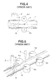
- FIG. 4 shows a pipe-producing method disclosed in JP-A-3-291176.
- a steel strip I is formed into an open pipe having edges 1a and 1b.
- the edges 1a and 1b are heated to a temperature of from 200 to 600 °C using a heat source 2 of a high frequency induction method or a high frequency resistance method.
- the method is a complex welding method which increases the welding speed by preheating the steel strip edges using the first heat source to make up the insufficient energy of the second heat source.
- the above-mentioned method aims to produce ferritic or austenitic stainless steel pipe.
- secondary operation properties such as cutting, bending, press forming and forging deteriorate owing to coarsening of crystal grains in the ferritic stainless steel.
- Quality of the steel pipe deteriorates owing to weld decay in the austenitic stainless steel.
- the preheating by the high frequency heat source 2 is limited to a temperature of from 200 to 600 °C. If, however, a size of steel pipe or a wall thickness of steel pipe increases, the increase of the welding speed cannot be expected by the preheating of a temperature of around 600 'C.
- Fig. 5 shows a pipe-producing method disclosed in JP-B-4-18954.
- preheating is carried out by using the induction heating coil 2 as the first heat source.
- Upstream of a V-converging point 1d where both edges 1a and 1b of the steel strip firstly contact each other is preheated to a degree that very little fusion occurs at the edges 1a and 1b of the steel strip.
- the joint face 1c of the steel strip at downstream of the V-converging point 1d is welded by irradiating high density energy beam 3 as a second heat source.
- the place of irradiation of high density energy beam 3 is carried out at downstream of the V-converging point 1d where both edges of the steel strip contact each other for the first time.
- the joint portion may open owing to spring back at downstream of the squeeze rolls 4a and 4b to induce undercut at the weld zone, or a solidification cracks may generate depending on the composition of the material.
- the squeeze rolls 4a, 4b and the squeeze rolls 5a, 5b clamp both edges of the steel strip to a degree that both edges are simply touch each other. Such clamp of both edges, however, has been hard to technologically attain, since there appears a gap between the squeeze rolls 4a and 4b and the squeeze rolls 5a and 5b caused by spring back.
- the present invention provides a method for producing a welded steel pipe comprising the steps recited in claim 1 below.
- the high density energy beam has a beam axis which is inclined toward a welded portion. See EP-A-739678 from which the present application is divided.
- the inclined high density energy beam should have an inclination of 5 to 20 degrees, defined as the angle formed by the beam axis and a vertical line at the irradiation point.
- a steel strip having two edges is formed into a cylindrical form so that the two edges face each other.
- the two edges of the steel strip are preheated to a temperature of a melting point or less by applying a high frequency electric current to the two edges.
- the preheated two edges are pressed each other by using squeeze rolls to form a joint portion including a joint line.
- a high density energy beam sufficient to fuse a full thickness of the steel strip is irradiated to a portion adjacent to a squeeze point to weld the joint portion.
- the squeeze point is a crossing point of a hypothetical line extending across centers of squeeze roll shafts and the joint line.
- An upset is controlled by using the squeeze rolls to reduce a weld defect.
- the upset is a difference between a coil width (mm) before pipe forming and a circumferencial length of pipe (mm).
- the preheating temperature of the edges of the steel strip is preferably from 600 to 1200 °C.
- the joint portion has "I" shape and the gap of joint is preferably 0 to 0.20 mm.
- the high density energy beam can be irradiated on the joint line at an upstream side of the squeeze point by 0 to 5 mm.
- the joint portion of the edges of steel strip is welded by laser and the upset given by the squeeze rolls is preferably 0.1 to 1 mm, The preheating zone and the adjacent portion of irradiation of the high density energy beam are shielded by a gas.
- a steel strip which is continuously supplied is formed into a cylindrical shape. Both edges of the steel strip are preheated to the melting point of the material or less, preferably to a temperature ranging from 600 to 1200 °C, using high frequency induction method or high frequency resistance method.
- a high density energy beam sufficient to fuse a full thickness of the steel strip is irradiated to a portion adjacent to a squeeze point to weld the the joint portion.
- the high density energy beam can be irradiated on the joint line at an upstream side of the squeeze point by 0 to 5 mm.
- An upset is controlled by using the squeeze rolls simultaneously with irradiating the high density energy beam.
- a preferable upset is from 0.1 to 1.0 mm.
- a maximum welding velocity for full penetration increases and the range of allowable welding speed is widened.
- a high quality welded steel pipe is produced without generating weld defects such as undercut, blowhole and longitudinal crack.
- Detection of a welding position is carried out by CCD camera which is placed just before the location where the both edges of the steel strip converge each other.
- the position of the joint portion of the both edges is taken of by the CCD camera and a welding torch is moved, synchronized with movement of the joint line. Thereafter, an excess portion of the weld zone is cut off.
- a portion adjacent to the weld zone is subjected to a quenching treatment by heating to a predetermined temperature using a high frequency induction power source and water-cooling. After the quenching treatment, tempering is perfomed by heating to a predetermined temperature. Alternatively, the portion adjacent to the weld zone is heated to a predetermined temperature and is air-cooled.
- Fig. 2 shows the results of the case that a electric-resistance-welded steel pipe was producd by using an ordinary pipe-forming mill in which the steel strip is continuously supplied and cylindrically formed.
- the electric-resistance-welded steel pipe comprises carbon steel and has a size of 508 mm of outer diameter and 12.7 mm of wall thickness. The hatched area in Fig. 2 indicates the area to provide satisfactory welding bead.
- the maximum welding speed increases with the preheating. It is well possible to weld in the preheating temperature of less than 600 °C.
- the preheating temperature of less than 600 °C however, deteriorates productivity because increase rate of welding speed becomes 1.5 or less.
- the increase rate of welding speed is defined by the ratio of the maximum welding speed at that temperature when the operation is presently performed to that at the room temperature.
- the preheating temperature is preferably 600 °C or more.
- the increase rate of welding speed is about 3.5, but a burn through bead appears which invites failure in obtaining satisfactory welding bead.
- the increase rate of welding speed is 3 or more. An improvement of productivity is obtained.
- the allowable range ⁇ V which is an adequate welding speed range to give satisfactory welding bead
- the maximum welding speed resulting in melt down bead and the maximum welding speed for full penetration significantly narrows compared with the case of preheat temperature of 1200°C or less.
- the preheating temperature is melting point of the material or less, preferably from 600 to 1200'C.
- Both edges of the steel strip formed into cylindrical shape opens owing to spring back at downstream of the crossing point of the hypothetical line extending across centers of squeeze roll shafts and the butt joint line.
- the crossing point is hereinafter referred to simply as "squeezing point". Accordingly, when welding is conducted under irradiation of high density energy beam to a place downstream of the squeezing point, a tensile stress occurs during the solidification of fused metal to induce weld defects such as undercut and solidification cracks depending on the chemical composition of the material.
- both edges of the cylindrical steel strip come close each other when they approach to the squeezing point, so the weld defects such as solidification cracks which occur at downstream of the squeezing point are avoided.
- the high density energy beam is irradiated to adjacent area of the squeezing point, and more preferably to a place by 0 to 0.5 mm upstream of the squeezing point.
- the place of irradiation corresponds to the point giving a joint gap of 0 to 0.20 mm.
- Steel pipes were produced by continuously forming a steel strip, electric-resistance-welding and using carbon dioxide gas laser with 20 kW of output. .
- the steel pipes comprise carbon steel and have the size of 508 mm of outer diameter and 7.5 mm of wall thickness, using carbon dioxide gas laser with 20 kW of output.
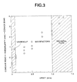
- Fig. 3 shows the result of test in which squeeze rolls clamped the external periphery of welding steel pipe to give compression deflection to the weld metal portion to a range of from 0 to 2.0 mm.
- the upset When the upset is less than 0.1 mm, the push-out of weld metal and the compression force are too small, so the preventive effect against weld defects is small to result in the generation of undercut and to remain weld defects.
- the upset exceeds 1.0 mm, then the width of weld metal is narrow to a range of from 0.5 to 2 mm, and most of the weld metal are pushed out, and the heat-affecting zone swells by metal flow. Hook cracks have generated attributably to the inclusion and to segregation of component after the swollen portion including bead was machined.
- upsetting of fused metal is essential for welding by high density energy beam, more preferably the upset length should be set in a range of from 0.1 to 1.0 mm.
- the preheating zone at the edges of the steel pipe using high frequency current, the weld zone, and the adjacent portion to the weld zone is preferably shielded by inert gas such as helium.
- the role of shielding is to suppress the remaining of oxide film and oxide generated during the preheating on the butt face of steel strip in the weld zone.
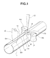
- Fig. 1 shows a schematic view of an apparatus for producing an electric-resistance-welded steel pipe which is used in the embodiment-1.
- a steel strip 1 is continuously supplied and formed into a cylindrical shape. Both edges 1a and 1b of the steel strip facing each other were preheated to a temperature of melting point of the material or less by using a high frequency resistance heating device 6.
- the contacts 6a and 6b of the high frequency resistance heating device 6 are arranged at upstream of the V-converging point 1d with a specified spacing.
- a high energy density laser beam 10 is irradiated to fuse the full thickness of the steel strip 1 to weld a butt joint portion 1c, and simultaneously, the butt joint portion is pressed to a specified upset to join together.
- the reference numbers 11a and 11b are top rolls which are installed to suppress the misalignment of butt joint portion 1c, at need.
- the chemical composition of starting material was 0.05 wt.% C, 0.15 wt.% Si, 1.20 wt.% Mn, 0.010 wt.% P, 0.001 wt.% S, 0.05wt.% Nb, and 0.03wt.% V.
- Carbon dioxide gas laser with 20 kW of maximum output was used.
- the shield gas was He or N 2 applied to the preheating area on edges of the steel strip and to the adjacent portion of the weld zone.
- Welded steel pipe was prepared by changing welding speed, preheating temperature, gap of butt joint, place of laser irradiation, and upset. When the weld zone swollen by upsetting, cutter or the like was applied to remove the build up.
- the impact property of the weld zone of the steel pipe produced by the present invention was evaluated by the fracture appearance transition temperature vTs (the temperature that the ductile fracture percentage becomes 50%) which was determined by Charpy impact test.
- Table 1 and Table 2 show the manufacturing conditions and the quality evaluation of Examples and Comparative Examples.
- Comparative Example No.1 showed the results of welding without preheating , using 2.0 m/min. of welding speed for full penetration.
- Examples No.1 through No.6 which were subjected to preheat ranging from 300 to 1000 °C showed increase of welding speed for full penetration, and that for 600 °C of preheat was approximately 1.5 times the speed at room temperature.
- Comparative Example No.3 which used the welding speed of 3.0 m/min. resulted in a burn through bead
- Comparative Example No.4 which used the welding speed of 7.5 m/min. resulted in an incomplete penetration.
- the allowable range of welding speed for the satisfactory bead is wide so as to be 3 m/min. for the case of 1200 °C of preheating temperature, and the allowable range significantly narrowed to about 1 m/min. for the case of 1300 °C of preheating temperature.
- Comparative Example No.9 which used 6.5 m/min. of welding speed resulted in the burn through bead, as in the case of 1300 °C of preheating temperature.
- Example No.11 provided the satisfactory bead at 7.0 m/min. of welding speed. Accordingly, the allowable welding speed range to obtain the satisfactory bead further narrowed.
- the burn through bead or the incomplete penetration bead are formed, the solidification of fused metal became unstable, and weld defects such as oxide inclusion and blow hole remained in the weld zone, and gave high Charpy transition temperature (vTs) as high as -40 °C or more.
- the preheat of both edges of the steel strip increased the welding speed for full penetration and improved the productivity compared with the case of the room temperature processing.
- preheating up to the melting point of the material results in the burn through bead, so the preheat temperature is preferably not to exceed the melting point of the material.
- the lower limit of preheat temperature is preferably to set at 600 °C or less.
- the upper limit thereof is preferably to set at 1200 °C or less.
- Comparative Example No.11 did not apply upsetting, and generated solidification cracks in the welded portion. Since the application of upsetting prevented the generation of solidification cracks, upsetting is essential. Comparative Examples No.12 and No.15 which applied upset less than 0.10 mm resulted in an undercut bead because of insufficient upsetting. Comparative Examples No.13, 14, and 16 which applied upset above 1.00 mm generated hook cracks owing to excessive upsetting. On the other hand, Examples No.12, 13, and 14 which applied upset in a range of from 0.10 to 1.00 mm provided satisfactory bead.
- upsetting is essential to obtain the satisfactory bead, and preferably the upset is preferably from 0.10 to 1.00 mm.
- Comparative Examples No.18, 19, 22, and 23 which received the irradiation of laser at downstream of the squeezing point generated solidification cracks within bead.
- the place of laser irradiation was selected at upstream of the squeezing point, generation of solidification crack was avoided.
- Comparative Examples No.17, 20, and 21 which received the irradiation of laser at more than 5 mm distant from the squeezing point, the gap of the butt joint became excessive and undercut generated.
- the place of laser irradiation was selected to a range of from 0.0 to 5.0 mm upstream of the squeezing point, satisfactory bead was obtained.
- the place of laser irradiation is preferably set to a range of from 0.0 to 5.0 mm upstream from the squeezing point.
- Comparative Examples No.24 and 25 did not use shield gas. Lots of oxide inclusion and blow holes appeared in the welded portion, and vTs degraded. On the other hand, Examples No.1 through No.21 used shield gas, and provided the satisfactory bead.
- shield gas is preferably important.
- a steel strip which was continuously supplied is formed into cylindrical shape; both edges of the steel strip are preheated to the melting point of the material or less than thereof, preferably to a temperature ranging from 600 to 1200 °C, using high frequency induction method or high frequency resistance method while irradiating high density energy beam, which beam enables to fuse full thickness of the steel strip, to a place adjacent to the crossing point of a hypothetical line extending across the centers of squeeze roll shafts and the butting line, more preferably at 0 to 5.0 mm upstream of the crossing point, under application of a compression force to a predetermined upset length to conduct welding; simultaneously the squeeze rolls apply compression of preferably 0.1 to 1.0 mm.
- a method for producing a electric-resistance-welded steel pipe of the present embodiment comprises: forming a steel strip into an open pipe; joining both edges of the steel strip together; irradiating high density energy beam to the joint portion with an inclination toward the welded portion along the welding line to weld the joint portion.
- the present embodiment applies the inclination, ⁇ , of the high density energy beam in a range of from 5 to 20 degrees.
- the beam inclination, ⁇ is an angle formed by the beam axis 14 and the normal line 15 to the base pipe at the beam irradiation point.
- the present embodiment comprises: forming a steel strip into an open pipe; preheating both edges of the steel strip to a temperature ranging from 300 to 1200°C using an electric resistance method or an induction heating method; joining the edges each other; and irradiating a high density energy beam to the joint portion to weld thereof.
- the present embodiment is characterized in that the applied beam of the high density energy irradiating to the joint portion of the open pipe is inclined toward the welded portion along the welding line.
- the reason why the beam inclined toward the welded portion along the welding line suppresses the above-described weld defects is the following.
- a beam which is converged to a point of welding has a small converged diameter ranging from 50 to 500 ⁇ m and is irradiated normal to the open pipe. Accordingly, the key hole formed during the welding gives small diameter thereof, and likely collapses due to a gravity sagging of fused metal at rear side of the fused basin, which tends to generate weld defects such as blow hole.
- the key hole area becomes wide owing to the gravity action to the fused metal at rear side of the fused basin. Consequently, the sagging of fused metal does not fill the key hole, thus the generation of weld defects such as key hole is avoided.
- Fig. 7 shows the evaluation of a generated number of weld defects and penetration depth by the expression of relation between the beam inclination and the welding speed.
- the line “A” shows the relation between the beam inclination and the generated number of weld defects.
- the line “B” shows the relation between the beam inclination and the penetration depth.
- the beam inclination is set to a range of from +5 to +20° toward the welded portion along the welding line.
- Fig. 6 is a schematic view of the method of the present embodiment.
- a steel strip 1 is formed into an open pipe while joining both edges thereof, and a laser beam 13 which was converged by a processing lens (not shown) is irradiated onto a joint portion 12 of the steel strip I at a beam inclination, ⁇ , toward the welded portion along the welding line to perform the welding of the joint portion 12.
- the beam inclination, ⁇ is an angle between the beam axis 14 of the laser beam 13 and the normal line 15 to the open pipe at the beam irradiation point. Only the inclination within a specific range toward the welded portion along the welding line gives satisfactory result as described below. Experiment proved that the range of inclination, ⁇ , is from 5 to 20°.
- the base material was a hot-rolled steel strips having thickness range of from 4.8 to 16 mm. These steel strip were formed into pipe having diameter of from 75 to 508 mm. The joint portion of each pipe was welded under irradiation of above-described laser beam 13.
- the welding wad conducted at the laser beam inclination ranging from -30 to +30° along the welding line.
- the welding condition was 20 kW of laser output, 40 to 290 mm/sec. of welding speed, and helium as shield gas.
- the joint portion of the open pipe was heated to 600 °C or 1000 °C by an electric resistance method, and the pipe -welding was performed under the above-described condition.
- the welded pipe was obtained under the condition, and the presence of blow holes and the penetration depth at the welded portion were checked.
- Table 3 and Table 4 show the pipe size, the welding condition, and the evaluation of the weld bead.
- No. Pipe dimensions Laser output (kW) Welding velocity v (mm/sec) Beam inclination (deg) Number of generated weld defects (- /m) Penetration depth (%) Diameter (mm) Wall thickness (mm) Comparative Example 1 75 4.8 20 160 -30 35 75 2 75 4.8 20 160 +30 0 70 3 168 7.5 20 160 -5 5 100 4 168 7.5 20 160 +25 0 75 5 168 7.5 15 125 +30 0 70 6 273 12.7 20 80 -30 40 70 7 273 12.7 20 80 -15 22 100 8 273 12.7 20 80 +25 0 75 9 508 16.0 20 40 -25 19 75 10 508 16.0 20 40 +30 0 70 This invention 11 75 4.8 20 160 +20 0 100 12 75 4.8 20 160 +5 0 100 13 168 7.5 20 160 +20 0 100 14 168 7.5 20 125 +15 0 100 15
- the criterion of evaluation for blow hole generation at the welded portion was that 3 or more of blow holes per 1 m of weld length is "bad” and that less than 3 of blow holes is "good”.
- the penetration depth was expressed by the ratio to the strip thickness.
- the criterion of evaluation of penetration depth was that the full penetration bead t is essential, or that the penetration depth ratio of 100 is evaluated as “good” and that the ratio of less than 100 is evaluated as "bad”.
- Comparative Examples No. 2, 4, 5, 8, and 10 used the beam inclination of +25° or more, and generated no weld defect. These Comparative Examples, however, failed to penetrate the weld bead into the strip thickness, and the penetration depth ratio was less than 100.
- Comparative Examples No. 1, 3, 6, 7, and 9 used the beam inclination of -5° or less, and many weld defects occurred.
- Comparative Examples No. 2, 3, 5, 6, 8, and 10 used the beam inclination of +25° or more, and generated no weld defect. These Comparative Examples, however, did not show full penetration, and the penetration depth ratio was less than 100.
- Comparative Examples No. 1, 4, 7, and 9 used the beam inclination of -5° or less, and many weld defects occurred
- the welding condition that was out of the range of the present embodiment generated weld defects or resulted in an incomplete penetration.
- only the beam inclination that satisfies the whole range of the present invention provided satisfactory weld beads without generating weld defect.
- the present embodiment is applicable not only for producing a electric-resistance-welded steel pipe but also for butt welding of general work.
- the sectional shape of an open pipe is arbitrarily selected, for example, as a circular or rectangular shape
- the present embodiment conducts welding by irradiating high density energy beam inclining to a specified angle toward the welded portion along the weld line.
- the welding is stably performed in a penetrating welding.
- weld defects such as undercut, blow hole, burn through, which have been inherent defects of laser welding process, are completely prevented.
- the welding provides satisfactory bead shape on both inside and outside of the steel pipe.
- the method of the present invention further improves the features of high efficiency of laser welding to increase the productivity.
Description
- The present invention relates to a method for producing a welded steel pipe, and more particularly to a method for producing a welded steel pipe using a high density energy beam as known from INABA Y ET AL: "THE PRESENT STATUS AND APPLICATIONS OF LASER PROCESSING: A HYBRID MANUFACTURING PROCESS FOR LASER WELDING OF STAINLESS STEEL PIPES" WELDING INTERNATIONAL, vol. 7, no. 6, 1 January 1993, pages 487-492.
- In conventional methods, a steel strip is formed into a cylindrical shape while transferring the steel strip so that both edges of the steel strip face each other. The both edges of the steel strip are welded to produce a steel pipe. Among the conventional methods, an electric-resistance-welding method is the most efficient. In the electric-resistance-welding method, a butt joint portion is heated and fused to form a fusion zone by using induction heating of high frequency electric current or applying a high frequency electric current to the butt joint portion from a contact chip. The fusion zone is pressed by squeeze rolls to remove impurities and oxides which exist in the fusion zone, thus the welding being done. However, oxides having high melting point are not removed and remain in a weld zone by oxygen in air during the heating and the fusion of the edges of the steel strip. The oxides comprise alloying elements such as Mn, Si, and Cr. The remained oxides may result in a weld defect called the "penetrator". To suppress oxidization and to obtain a high quality welded steel pipe, gas shielding is applied. The gas shielding, however, gives not sufficient effect.
- A pipe-producing method using high density energy beam such as laser beam has been developed on the background described above. The method is a welding method to fuse the edges of a steel strip under irradiation of high density energy beam. It is known that since the method avoids exposing the fused metal to atmospheric air, weld defects such as oxide inclusion are hard to generate, and high quality welded steel pipe is obtained.
- The method using high density energy beam is disclosed in JP-A-3-291176 which is published on December 20, 1991 and JP-B-4-18954 which is published March 30, 1992 (the terms "JP-A-" and "JP-B" referred to herein signify "unexamined Japanese patent publication" and "examined Japanese patent publication", respectively). Fig. 4 shows a pipe-producing method disclosed in JP-A-3-291176. A steel strip I is formed into an open pipe having edges 1a and 1b. The edges 1a and 1b are heated to a temperature of from 200 to 600 °C using a
heat source 2 of a high frequency induction method or a high frequency resistance method. Then a high density energy beam as thesecond heat source 3 is irradiated to a portion 1c adjacent tosqueeze rolls 4a and 4b to weld the portion. The method is a complex welding method which increases the welding speed by preheating the steel strip edges using the first heat source to make up the insufficient energy of the second heat source. - The above-mentioned method aims to produce ferritic or austenitic stainless steel pipe. But secondary operation properties such as cutting, bending, press forming and forging deteriorate owing to coarsening of crystal grains in the ferritic stainless steel. Quality of the steel pipe deteriorates owing to weld decay in the austenitic stainless steel. For the above-mentioned problems, the preheating by the high
frequency heat source 2 is limited to a temperature of from 200 to 600 °C. If, however, a size of steel pipe or a wall thickness of steel pipe increases, the increase of the welding speed cannot be expected by the preheating of a temperature of around 600 'C. - Fig. 5 shows a pipe-producing method disclosed in JP-B-4-18954. According to the pipe-producing method, preheating is carried out by using the
induction heating coil 2 as the first heat source. Upstream of a V-converging point 1d where both edges 1a and 1b of the steel strip firstly contact each other is preheated to a degree that very little fusion occurs at the edges 1a and 1b of the steel strip. The joint face 1c of the steel strip at downstream of the V-converging point 1d is welded by irradiating highdensity energy beam 3 as a second heat source. In a portion between the V-converging point 1d and the fusion zone by the high density energy beam, and in a portion downstream of the fusion zone, a clamping force is applied to both edges of the steel strip to a degree that both edges simply touch each other. - In this method, the place of irradiation of high
density energy beam 3 is carried out at downstream of the V-converging point 1d where both edges of the steel strip contact each other for the first time. As shown in Fig. 5, however, the joint portion may open owing to spring back at downstream of thesqueeze rolls 4a and 4b to induce undercut at the weld zone, or a solidification cracks may generate depending on the composition of the material. The squeeze rolls 4a, 4b and the squeeze rolls 5a, 5b clamp both edges of the steel strip to a degree that both edges are simply touch each other. Such clamp of both edges, however, has been hard to technologically attain, since there appears a gap between thesqueeze rolls 4a and 4b and thesqueeze rolls - It is an object of the present invention to provide a method for producing a welded steel pipe of high quality with high efficiency and without weld defects
- To attain the object, the present invention provides a method for producing a welded steel pipe comprising the steps recited in claim 1 below.
- Preferred embodiments of the present invention are described in
dependent claims 2 to 4. - Preferably, the high density energy beam has a beam axis which is inclined toward a welded portion. See EP-A-739678 from which the present application is divided.
- The inclined high density energy beam should have an inclination of 5 to 20 degrees, defined as the angle formed by the beam axis and a vertical line at the irradiation point.
-
- Fig. 1 is a schematic view of an apparatus which is used in the embodiment-1.
- Fig. 2 is a graph showing a relation of preheating temperature, maximum welding velocity for full penetration, and quality of weld zone according to the embodiment-1.
- Fig. 3 is a graph showing a relation of upset and quality of weld zone according to the embodiment-1.
- Fig. 4 is an explanatory view of a prior art.
- Fig. 5 is another explanatory view of another prior art.
- Fig. 6 is a schematic view of the embodiment-2.
- Fig. 7 is a graph showing a relations of a beam inclination to generated weld defects in number and to penetration depth according to the embodiment-2.
-
- In the embodiment-1, a steel strip having two edges is formed into a cylindrical form so that the two edges face each other. The two edges of the steel strip are preheated to a temperature of a melting point or less by applying a high frequency electric current to the two edges. The preheated two edges are pressed each other by using squeeze rolls to form a joint portion including a joint line. A high density energy beam sufficient to fuse a full thickness of the steel strip is irradiated to a portion adjacent to a squeeze point to weld the joint portion. The squeeze point is a crossing point of a hypothetical line extending across centers of squeeze roll shafts and the joint line. An upset is controlled by using the squeeze rolls to reduce a weld defect. The upset is a difference between a coil width (mm) before pipe forming and a circumferencial length of pipe (mm).
- The preheating temperature of the edges of the steel strip is preferably from 600 to 1200 °C. The joint portion has "I" shape and the gap of joint is preferably 0 to 0.20 mm. The high density energy beam can be irradiated on the joint line at an upstream side of the squeeze point by 0 to 5 mm. The joint portion of the edges of steel strip is welded by laser and the upset given by the squeeze rolls is preferably 0.1 to 1 mm, The preheating zone and the adjacent portion of irradiation of the high density energy beam are shielded by a gas.
- According to the embodiment-1, a steel strip which is continuously supplied is formed into a cylindrical shape. Both edges of the steel strip are preheated to the melting point of the material or less, preferably to a temperature ranging from 600 to 1200 °C, using high frequency induction method or high frequency resistance method. A high density energy beam sufficient to fuse a full thickness of the steel strip is irradiated to a portion adjacent to a squeeze point to weld the the joint portion. The high density energy beam can be irradiated on the joint line at an upstream side of the squeeze point by 0 to 5 mm. An upset is controlled by using the squeeze rolls simultaneously with irradiating the high density energy beam. A preferable upset is from 0.1 to 1.0 mm.
- The above described method provides the following advantages.
- A maximum welding velocity for full penetration increases and the range of allowable welding speed is widened. A high quality welded steel pipe is produced without generating weld defects such as undercut, blowhole and longitudinal crack.
- Detection of a welding position is carried out by CCD camera which is placed just before the location where the both edges of the steel strip converge each other. The position of the joint portion of the both edges is taken of by the CCD camera and a welding torch is moved, synchronized with movement of the joint line. Thereafter, an excess portion of the weld zone is cut off. Subsequently, a portion adjacent to the weld zone is subjected to a quenching treatment by heating to a predetermined temperature using a high frequency induction power source and water-cooling. After the quenching treatment, tempering is perfomed by heating to a predetermined temperature. Alternatively, the portion adjacent to the weld zone is heated to a predetermined temperature and is air-cooled.
- Now preferable individual constitutions of the present embodiment will be described.
- An effect of the preheating temperature on the welding temperature was investigated. The preheating temperature was changed from room temperature to the melting point of the steel strip. Welding was conducted using a carbon dioxide gas laser with 20 kW of output. The maximum welding velocity for full penetration and the quality of weld zone were studied. Fig. 2 shows the results of the case that a electric-resistance-welded steel pipe was producd by using an ordinary pipe-forming mill in which the steel strip is continuously supplied and cylindrically formed. The electric-resistance-welded steel pipe comprises carbon steel and has a size of 508 mm of outer diameter and 12.7 mm of wall thickness. The hatched area in Fig. 2 indicates the area to provide satisfactory welding bead.
- As seen in Fig. 2, the maximum welding speed increases with the preheating. It is well possible to weld in the preheating temperature of less than 600 °C. The preheating temperature of less than 600 °C, however, deteriorates productivity because increase rate of welding speed becomes 1.5 or less. The increase rate of welding speed is defined by the ratio of the maximum welding speed at that temperature when the operation is presently performed to that at the room temperature.
- Accordingly, to obtain the increase rate of 1.5 or more, the preheating temperature is preferably 600 °C or more.
- When the preheating temperature is over melting point, the increase rate of welding speed is about 3.5, but a burn through bead appears which invites failure in obtaining satisfactory welding bead.
- When the preheating temperature is over 1200 °C and below the melting point, the increase rate of welding speed is 3 or more. An improvement of productivity is obtained. In that range of temperature, however, the allowable range Δ V ( which is an adequate welding speed range to give satisfactory welding bead) between the maximum welding speed resulting in melt down bead and the maximum welding speed for full penetration significantly narrows compared with the case of preheat temperature of 1200°C or less.
- Therefore, the preheating temperature is melting point of the material or less, preferably from 600 to 1200'C.
- Both edges of the steel strip formed into cylindrical shape opens owing to spring back at downstream of the crossing point of the hypothetical line extending across centers of squeeze roll shafts and the butt joint line. The crossing point is hereinafter referred to simply as "squeezing point". Accordingly, when welding is conducted under irradiation of high density energy beam to a place downstream of the squeezing point, a tensile stress occurs during the solidification of fused metal to induce weld defects such as undercut and solidification cracks depending on the chemical composition of the material. On the other hand, at upstream of the squeezing point, both edges of the cylindrical steel strip come close each other when they approach to the squeezing point, so the weld defects such as solidification cracks which occur at downstream of the squeezing point are avoided.
- Consequently, it is important to carry out welding by irradiating high density energy beam to a portion adjacent to the squeezing point. Downstream of the squeezing point is, however, not preferable for the portion of irradiation of high density energy beam, where tensile stress is applied to the weld portion, and upstream of the squeezing point is preferable. Even in upstream of the squeezing point, joint gap of above 0.20 mm induces undercut defect owing to the excessive gap. The joint gap of 0.20 mm corresponds to the point of about 5 mm upstream from the squeezing point.
- Conclusively, the high density energy beam is irradiated to adjacent area of the squeezing point, and more preferably to a place by 0 to 0.5 mm upstream of the squeezing point. The place of irradiation corresponds to the point giving a joint gap of 0 to 0.20 mm.
- In a pipe-producing welding method which uses high density energy beam, fused metal having a narrow width is produced at a high speed, so the solidification rapidly occurs, undercut occurs on the bead portion at rear side and solidification cracks likely occur depending on chemical composition of the material. Furthermore, gas and metallic vapor are likely entrapped to generate blow holes. Application of upsetting using squeeze rolls is a means for preventing those type of defects. That is, undercut is prevented by push-out of fused weld metal toward the plate thickness direction by upsetting. Upsetting pushes out the welding metal, and the push-out action collapses blow holes. On the other hand, solidification cracks of welding metal is prevented by applying compression force to the weld metal by upsetting.
- The preventive effect against the generation of weld defects using upsetting was experimentally confirmed. Steel pipes were produced by continuously forming a steel strip, electric-resistance-welding and using carbon dioxide gas laser with 20 kW of output. . The steel pipes comprise carbon steel and have the size of 508 mm of outer diameter and 7.5 mm of wall thickness, using carbon dioxide gas laser with 20 kW of output. Fig. 3 shows the result of test in which squeeze rolls clamped the external periphery of welding steel pipe to give compression deflection to the weld metal portion to a range of from 0 to 2.0 mm. When the upset is less than 0.1 mm, the push-out of weld metal and the compression force are too small, so the preventive effect against weld defects is small to result in the generation of undercut and to remain weld defects. When the upset exceeds 1.0 mm, then the width of weld metal is narrow to a range of from 0.5 to 2 mm, and most of the weld metal are pushed out, and the heat-affecting zone swells by metal flow. Hook cracks have generated attributably to the inclusion and to segregation of component after the swollen portion including bead was machined.
- Therefore, upsetting of fused metal is essential for welding by high density energy beam, more preferably the upset length should be set in a range of from 0.1 to 1.0 mm.
- During the pipe-producing process, the preheating zone at the edges of the steel pipe using high frequency current, the weld zone, and the adjacent portion to the weld zone is preferably shielded by inert gas such as helium. The role of shielding is to suppress the remaining of oxide film and oxide generated during the preheating on the butt face of steel strip in the weld zone.
- Fig. 1 shows a schematic view of an apparatus for producing an electric-resistance-welded steel pipe which is used in the embodiment-1.
- According to the example, a steel strip 1 is continuously supplied and formed into a cylindrical shape. Both edges 1a and 1b of the steel strip facing each other were preheated to a temperature of melting point of the material or less by using a high frequency
resistance heating device 6. Thecontacts 6a and 6b of the high frequencyresistance heating device 6 are arranged at upstream of the V-converging point 1d with a specified spacing. At an adjacent portion of the squeezingpoint 9, which is a crossing point of thehypothetical line 7 extending across the centers ofsqueeze roll shafts 4a and 4b and a buttjoint line 8 between the edges 1a and 1b of the steel strip, a high energydensity laser beam 10 is irradiated to fuse the full thickness of the steel strip 1 to weld a butt joint portion 1c, and simultaneously, the butt joint portion is pressed to a specified upset to join together. Thereference numbers 11a and 11b are top rolls which are installed to suppress the misalignment of butt joint portion 1c, at need. - The following are the results of production of electric-resistance-welded steel pipes comprising carbon steel and having the size of 304 to 508 mm of outer diameter and 5.0 to 12.7 mm of wall thickness using the above-described manufacturing equipment.
- The chemical composition of starting material was 0.05 wt.% C, 0.15 wt.% Si, 1.20 wt.% Mn, 0.010 wt.% P, 0.001 wt.% S, 0.05wt.% Nb, and 0.03wt.% V.
- Carbon dioxide gas laser with 20 kW of maximum output was used. Regarding the producing condition, the shield gas was He or N2 applied to the preheating area on edges of the steel strip and to the adjacent portion of the weld zone. Welded steel pipe was prepared by changing welding speed, preheating temperature, gap of butt joint, place of laser irradiation, and upset. When the weld zone swollen by upsetting, cutter or the like was applied to remove the build up.
- The expression of the place of laser irradiation was "-" for upstream of the squeezing point and "+" for downstream thereof.
- The quality of thus prepared welded steel pipe was evaluated by the criteria given below.
- As for the bead shape, appearance inspection was given to observe the bead penetration across the full thickness, the undercut on the bead surface, the presence of burn through, and the generation of hook cracks after bead machined.
- For the weld defects inside of the weld zone, nondestructive inspection was applied to check the number of blow holes and inclusions and the presence of solidification cracks.
- The impact property of the weld zone of the steel pipe produced by the present invention was evaluated by the fracture appearance transition temperature vTs (the temperature that the ductile fracture percentage becomes 50%) which was determined by Charpy impact test.
- These evaluation tests were applied to the weld zone which was treated by quenching and tempering ( heating to 950°Cwater quenching

- Table 1 and Table 2 show the manufacturing conditions and the quality evaluation of Examples and Comparative Examples.


- The effect of preheating was investigated in Examples No.1 through No.11 and Comparative Examples No.1 through No. 10.
- Comparative Example No.1 showed the results of welding without preheating , using 2.0 m/min. of welding speed for full penetration. On the other hand, Examples No.1 through No.6 which were subjected to preheat ranging from 300 to 1000 °C showed increase of welding speed for full penetration, and that for 600 °C of preheat was approximately 1.5 times the speed at room temperature.
- In the case that the preheat was carried out at 1200 °C, Comparative Example No.3 which used the welding speed of 3.0 m/min. resulted in a burn through bead, and Comparative Example No.4 which used the welding speed of 7.5 m/min. resulted in an incomplete penetration. Examples No.7 and No.8 which used the welding speed of 4.0 m/min. and 7.0 m/min., respectively, provided a satisfactory bead.
- For the case of 1300 °C of preheat, Examples No.9 and No.10 which used the welding speed of 6.0 m/min. and 7.0 m/min., respectively, provided the satisfactory bead. Comparative Examples No.5 through No.7 which used the welding speed of 4.0 m/min. and 5.5 m/min., respectively, resulted in the burn through bead, and Comparative Example No.8 which used the welding speed of 7.5 m/min. resulted in the incomplete penetration.
- As described above, the allowable range of welding speed for the satisfactory bead is wide so as to be 3 m/min. for the case of 1200 °C of preheating temperature, and the allowable range significantly narrowed to about 1 m/min. for the case of 1300 °C of preheating temperature.
- In the case of 1400 °C of preheating temperature, Comparative Example No.9 which used 6.5 m/min. of welding speed resulted in the burn through bead, as in the case of 1300 °C of preheating temperature. Example No.11 provided the satisfactory bead at 7.0 m/min. of welding speed. Accordingly, the allowable welding speed range to obtain the satisfactory bead further narrowed. In the case that the burn through bead or the incomplete penetration bead are formed, the solidification of fused metal became unstable, and weld defects such as oxide inclusion and blow hole remained in the weld zone, and gave high Charpy transition temperature (vTs) as high as -40 °C or more.
- In this manner, the preheat of both edges of the steel strip increased the welding speed for full penetration and improved the productivity compared with the case of the room temperature processing. However, preheating up to the melting point of the material results in the burn through bead, so the preheat temperature is preferably not to exceed the melting point of the material. When the productivity is taken into account, the lower limit of preheat temperature is preferably to set at 600 °C or less. When the allowable welding speed range for the satisfactory bead, the upper limit thereof is preferably to set at 1200 °C or less.
- The effect of upsetting was investigated in Examples No.12 through No.14 and Comparative Examples No.11 through No.16.
- Comparative Example No.11 did not apply upsetting, and generated solidification cracks in the welded portion. Since the application of upsetting prevented the generation of solidification cracks, upsetting is essential. Comparative Examples No.12 and No.15 which applied upset less than 0.10 mm resulted in an undercut bead because of insufficient upsetting. Comparative Examples No.13, 14, and 16 which applied upset above 1.00 mm generated hook cracks owing to excessive upsetting. On the other hand, Examples No.12, 13, and 14 which applied upset in a range of from 0.10 to 1.00 mm provided satisfactory bead.
- Consequently, upsetting is essential to obtain the satisfactory bead, and preferably the upset is preferably from 0.10 to 1.00 mm.
- The effect of place of laser irradiation was investigated in Examples No.15 through No.21 and Comparative Examples No.17 through No.23.
- Comparative Examples No.18, 19, 22, and 23 which received the irradiation of laser at downstream of the squeezing point generated solidification cracks within bead. When the place of laser irradiation was selected at upstream of the squeezing point, generation of solidification crack was avoided. Comparative Examples No.17, 20, and 21 which received the irradiation of laser at more than 5 mm distant from the squeezing point, the gap of the butt joint became excessive and undercut generated. On the other hand, when the place of laser irradiation was selected to a range of from 0.0 to 5.0 mm upstream of the squeezing point, satisfactory bead was obtained.
- Accordingly, the place of laser irradiation is preferably set to a range of from 0.0 to 5.0 mm upstream from the squeezing point.
- The effect of shield gas was investigated in Comparative Examples No.24 and 25.
- Comparative Examples No.24 and 25 did not use shield gas. Lots of oxide inclusion and blow holes appeared in the welded portion, and vTs degraded. On the other hand, Examples No.1 through No.21 used shield gas, and provided the satisfactory bead.
- Therefore, shield gas is preferably important.
- As described above, in Comparative Examples which were processed at outside of the scope of the present embodiment, when the material is preheated to the melting point or more thereof, when upsetting is not applied to the fused metal portion to press it against squeeze rolls, or when no shield gas is used, bead shape degraded and weld defects generated. Also vTs became -40 °C or above.
- To the contrary, in Examples No.1 through No.21 which used the condition for manufacturing welded steel pipe of the present embodiment, bead shape was satisfactory, weld defect was not generated, and satisfactory vTs value was obtained.
- According to the present embodiment, a steel strip which was continuously supplied is formed into cylindrical shape; both edges of the steel strip are preheated to the melting point of the material or less than thereof, preferably to a temperature ranging from 600 to 1200 °C, using high frequency induction method or high frequency resistance method while irradiating high density energy beam, which beam enables to fuse full thickness of the steel strip, to a place adjacent to the crossing point of a hypothetical line extending across the centers of squeeze roll shafts and the butting line, more preferably at 0 to 5.0 mm upstream of the crossing point, under application of a compression force to a predetermined upset length to conduct welding; simultaneously the squeeze rolls apply compression of preferably 0.1 to 1.0 mm. With the procedure, a high quality welded steel pipe is produced at a high efficiency without having weld defects such as undercut, blowhole, longitudinal crack.
- A method for producing a electric-resistance-welded steel pipe of the present embodiment comprises: forming a steel strip into an open pipe; joining both edges of the steel strip together; irradiating high density energy beam to the joint portion with an inclination toward the welded portion along the welding line to weld the joint portion.
- The present embodiment applies the inclination, , of the high density energy beam in a range of from 5 to 20 degrees. As shown in Fig.6, the beam inclination, , is an angle formed by the
beam axis 14 and thenormal line 15 to the base pipe at the beam irradiation point. - The present embodiment comprises: forming a steel strip into an open pipe; preheating both edges of the steel strip to a temperature ranging from 300 to 1200°C using an electric resistance method or an induction heating method; joining the edges each other; and irradiating a high density energy beam to the joint portion to weld thereof.
- The present embodiment is characterized in that the applied beam of the high density energy irradiating to the joint portion of the open pipe is inclined toward the welded portion along the welding line. The reason why the beam inclined toward the welded portion along the welding line suppresses the above-described weld defects is the following. Generally, a beam which is converged to a point of welding has a small converged diameter ranging from 50 to 500 µm and is irradiated normal to the open pipe. Accordingly, the key hole formed during the welding gives small diameter thereof, and likely collapses due to a gravity sagging of fused metal at rear side of the fused basin, which tends to generate weld defects such as blow hole.
- On the other hand, when the beam is inclined toward the welded portion along the weld line, as in the case of the present embodiment , the key hole area becomes wide owing to the gravity action to the fused metal at rear side of the fused basin. Consequently, the sagging of fused metal does not fill the key hole, thus the generation of weld defects such as key hole is avoided.
- Experiment proved that the optimum inclination, , of the beam is in a range of from 5 to 20 degrees toward the welded portion along the welding line. The experiment was conducted using a carbon steel strip having 12 mm of thickness, a carbon dioxide gas laser with 20 kW of output, and with varied beam inclinations and welding speeds. The result is shown in Fig. 7. Fig. 7 shows the evaluation of a generated number of weld defects and penetration depth by the expression of relation between the beam inclination and the welding speed. The line "A" shows the relation between the beam inclination and the generated number of weld defects. The line "B" shows the relation between the beam inclination and the penetration depth.
- In Fig.7, vertical irradiation of beam onto the open pipe is taken as "0°". The beam inclined toward the welded portion is taken as "+", and the beam inclined toward the not yet welded portion is taken as "-". Regarding the number of generated blow holes in relation to the beam inclination, the generation of blow holes was suppressed when the inclination became +5° or more independent of the welding speed. Within a beam inclination range of from -20 to +20°, the penetration depth at the weld bead portion gave about 0.8 times or more to the penetration depth at beam inclination of 0° (or the penetration depth ratio) where the depth reached to maximum level. Thus the beam inclination range of from -20 to +20° does not impair productivity. In the case that the beam inclination is outside of the range of -20 to +20°, however, the ratio of penetration depth became 0.8 or less to degrade the productivity. Therefore, the beam inclination is set to a range of from +5 to +20° toward the welded portion along the welding line.
- Fig. 6 is a schematic view of the method of the present embodiment.
- As seen in Fig. 6, a steel strip 1 is formed into an open pipe while joining both edges thereof, and a
laser beam 13 which was converged by a processing lens (not shown) is irradiated onto ajoint portion 12 of the steel strip I at a beam inclination, , toward the welded portion along the welding line to perform the welding of thejoint portion 12. The beam inclination, , is an angle between thebeam axis 14 of thelaser beam 13 and thenormal line 15 to the open pipe at the beam irradiation point. Only the inclination within a specific range toward the welded portion along the welding line gives satisfactory result as described below. Experiment proved that the range of inclination, , is from 5 to 20°. - The effect of the present invention will be described below referring to the embodiment.
- The base material was a hot-rolled steel strips having thickness range of from 4.8 to 16 mm. These steel strip were formed into pipe having diameter of from 75 to 508 mm. The joint portion of each pipe was welded under irradiation of above-described
laser beam 13. - The welding wad conducted at the laser beam inclination ranging from -30 to +30° along the welding line. The welding condition was 20 kW of laser output, 40 to 290 mm/sec. of welding speed, and helium as shield gas. The joint portion of the open pipe was heated to 600 °C or 1000 °C by an electric resistance method, and the pipe -welding was performed under the above-described condition.
- The welded pipe was obtained under the condition, and the presence of blow holes and the penetration depth at the welded portion were checked.
- Table 3 and Table 4 show the pipe size, the welding condition, and the evaluation of the weld bead.
No. Pipe dimensions Laser output
(kW)Welding velocity
v
(mm/sec)Beam inclination
(deg)Number of generated weld defects
(- /m)Penetration depth
(%)Diameter
(mm)Wall thickness
(mm)Comparative Example 1 75 4.8 20 160 -30 35 75 2 75 4.8 20 160 +30 0 70 3 168 7.5 20 160 -5 5 100 4 168 7.5 20 160 +25 0 75 5 168 7.5 15 125 +30 0 70 6 273 12.7 20 80 -30 40 70 7 273 12.7 20 80 -15 22 100 8 273 12.7 20 80 +25 0 75 9 508 16.0 20 40 -25 19 75 10 508 16.0 20 40 +30 0 70 This invention 11 75 4.8 20 160 +20 0 100 12 75 4.8 20 160 +5 0 100 13 168 7.5 20 160 +20 0 100 14 168 7.5 20 125 +15 0 100 15 168 7.5 15 125 +5 0 100 16 273 12.7 20 80 +20 0 100 17 273 12.7 20 80 +5 0 100 18 273 12.7 20 80 +15 0 100 19 508 16.0 20 40 +20 0 100 20 508 16.0 20 40 +5 0 100 No Pipe dimensions Preheat tempera ture
(°C)Laser output
(kW)Welding velocity
v
(mm/sec)Beam inclination
(deg)Number of generated weld defects
(- /m)Penetration depth
(%)Diameter
(mm)Wall thickness
(mm)Comparative Example 1 168 7.5 600 20 210 -5 8 100 2 168 7.5 600 20 210 +25 0 75 3 168 7.5 600 15 160 +30 0 70 4 168 7.5 1000 20 290 -5 7 100 5 168 7.5 1000 20 290 +25 0 75 6 168 7.5 1000 15 225 +33 0 70 7 508 16.0 600 20 55 -25 21 75 8 508 16.0 600 20 55 +30 0 70 9 508 16.0 1000 20 75 -25 19 75 10 508 16.0 1000 20 75 +30 0 70 This invention 11 168 7.5 600 20 210 +20 0 100 12 168 7.5 600 20 160 +15 0 100 13 168 7.5 600 15 160 +5 0 100 14 168 7.5 1000 20 290 +20 0 100 15 168 7.5 1000 20 225 +15 0 100 16 168 7.5 1000 15 225 +5 0 100 17 508 16.0 600 20 55 +20 0 100 18 508 16.0 600 20 55 +5 0 100 19 508 16.0 1000 20 75 +20 0 100 20 508 16.0 1000 20 75 +5 0 100 - The criterion of evaluation for blow hole generation at the welded portion was that 3 or more of blow holes per 1 m of weld length is "bad" and that less than 3 of blow holes is "good". The penetration depth was expressed by the ratio to the strip thickness. The criterion of evaluation of penetration depth was that the full penetration bead t is essential, or that the penetration depth ratio of 100 is evaluated as "good" and that the ratio of less than 100 is evaluated as "bad".
- In Table 3, Comparative Examples No. 2, 4, 5, 8, and 10 used the beam inclination of +25° or more, and generated no weld defect. These Comparative Examples, however, failed to penetrate the weld bead into the strip thickness, and the penetration depth ratio was less than 100.
- Comparative Examples No. 1, 3, 6, 7, and 9 used the beam inclination of -5° or less, and many weld defects occurred.
- In Table 4, Comparative Examples No. 2, 3, 5, 6, 8, and 10 used the beam inclination of +25° or more, and generated no weld defect. These Comparative Examples, however, did not show full penetration, and the penetration depth ratio was less than 100.
- Comparative Examples No. 1, 4, 7, and 9 used the beam inclination of -5° or less, and many weld defects occurred
- As described above, the welding condition that was out of the range of the present embodiment generated weld defects or resulted in an incomplete penetration. On the other hand, only the beam inclination that satisfies the whole range of the present invention provided satisfactory weld beads without generating weld defect.
- Consequently, a welding condition outside of the range of the present embodiment degraded bead shape or generated weld defects. To the contrary, it is understood that only the case where the whole welding conditions of the present embodiment are satisfied provides satisfactory bead shape without containing weld defect.
- The present embodiment is applicable not only for producing a electric-resistance-welded steel pipe but also for butt welding of general work. The sectional shape of an open pipe is arbitrarily selected, for example, as a circular or rectangular shape
- As described above, the present embodiment conducts welding by irradiating high density energy beam inclining to a specified angle toward the welded portion along the weld line. The welding is stably performed in a penetrating welding. Thus the weld defects such as undercut, blow hole, burn through, which have been inherent defects of laser welding process, are completely prevented. In addition, the welding provides satisfactory bead shape on both inside and outside of the steel pipe. Furthermore, the method of the present invention further improves the features of high efficiency of laser welding to increase the productivity.
Claims (4)
- A method for producing a welded steel pipe from steel strip (1) having two edges (1a, 1b) the method comprising the steps of:characterised by(a) forming the steel strip into a cylindrical form so that the two edges (1a, 1b) face each other;(b) gas shielding the two edges (1a, 1b) with an inert gas;(c) preheating the two edges (1a, 1b) of the steel strip (1) to a temperature of a melting point or less by applying a high frequency electric current to the two edges;(d) pressing the two edges (1a, 1b) of the steel strip against each other by using at least one pair of squeeze rolls (4a, 4b) each with its own shaft, at a squeeze point defined by a crossing point of a hypothetical line joining the shaft centres of the squeeze roll pair and a joint portion (9) including a joint line;(e) irradiating the said strip edges with an energy beam (13) having an axis (14) and a density high enough to fuse a full thickness of the steel strip (1) at a location on the joint portion (9) upstream of the squeeze point, to weld the strip edges (1a, 1b) together at the joint portion (9) to form said pipe; and(f) controlling the squeeze rolls (4a, 4b) to create an upset which reduces weld defects in the joint portion (9), the step (d) being performed simultaneously, and said upset being defined as the difference between the coil width of the steel strip before pipe forming and the circumferential length of the formed pipe,
positioning said beam axis (14) not more than 5mm upstream of said squeeze point;
providing a pair (11a, 11b) of top rollers upstream of said beam axis for suppressing misalignment of the two edges (1a, 1b) at the joint portion (9); and
controlling said squeeze rolls (4a, 4b) to create an upset of from 0.1 to 1mm. - A method according to claim 1, wherein said preheating of the step (b) comprises preheating the two edges (1a, 1b) of the steel strip to a temperature of 600 to 1200°C.
- A method according to claim 1 or 2, wherein said joint portion (9) has an "I" shape and the joint portion has a gap of 0 to 0.20 mm.
- A method according to any one of the preceding claims, wherein
said irradiating of the step (e) comprises irradiating by laser.
Applications Claiming Priority (3)
| Application Number | Priority Date | Filing Date | Title |
|---|---|---|---|
| JP10497695 | 1995-04-28 | ||
| JP7104976A JPH08300172A (en) | 1995-04-28 | 1995-04-28 | Manufacture of welded steel tube |
| EP96106621A EP0739678B1 (en) | 1995-04-28 | 1996-04-26 | Method for producing an electric-resistance-welded steel pipe |
Related Parent Applications (1)
| Application Number | Title | Priority Date | Filing Date |
|---|---|---|---|
| EP96106621A Division EP0739678B1 (en) | 1995-04-28 | 1996-04-26 | Method for producing an electric-resistance-welded steel pipe |
Publications (2)
| Publication Number | Publication Date |
|---|---|
| EP0933159A1 EP0933159A1 (en) | 1999-08-04 |
| EP0933159B1 true EP0933159B1 (en) | 2003-02-26 |
Family
ID=14395132
Family Applications (2)
| Application Number | Title | Priority Date | Filing Date |
|---|---|---|---|
| EP99102861A Expired - Lifetime EP0933159B1 (en) | 1995-04-28 | 1996-04-26 | Method for producing a welded steel pipe |
| EP96106621A Expired - Lifetime EP0739678B1 (en) | 1995-04-28 | 1996-04-26 | Method for producing an electric-resistance-welded steel pipe |
Family Applications After (1)
| Application Number | Title | Priority Date | Filing Date |
|---|---|---|---|
| EP96106621A Expired - Lifetime EP0739678B1 (en) | 1995-04-28 | 1996-04-26 | Method for producing an electric-resistance-welded steel pipe |
Country Status (8)
| Country | Link |
|---|---|
| US (1) | US5900079A (en) |
| EP (2) | EP0933159B1 (en) |
| JP (1) | JPH08300172A (en) |
| KR (1) | KR100228252B1 (en) |
| CN (1) | CN1050556C (en) |
| CA (1) | CA2175169C (en) |
| DE (2) | DE69626425T2 (en) |
| TW (1) | TW400262B (en) |
Families Citing this family (54)
| Publication number | Priority date | Publication date | Assignee | Title |
|---|---|---|---|---|
| US5968380A (en) * | 1994-07-27 | 1999-10-19 | Sumitomo Metal Industries Limited | Method for producing laser-welded tubes and apparatus for producing the same |
| FR2756641B1 (en) * | 1996-12-03 | 1999-01-15 | Fileca Foptica | OPTICAL MODULE MANUFACTURING MACHINE |
| CN1068268C (en) * | 1997-07-09 | 2001-07-11 | 上海康德工程技术研究所 | Technology and technique for low alloy (alloy) structural steel welding steel pipe |
| JP3971864B2 (en) * | 1999-04-02 | 2007-09-05 | 大陽日酸株式会社 | Stainless steel piping joining method |
| CA2326896A1 (en) * | 1999-11-26 | 2001-05-26 | Powerlasers Ltd. | Inclined beam lap welding |
| JP3399445B2 (en) * | 2000-05-25 | 2003-04-21 | 三菱電機株式会社 | Strip connection method in steel plate continuous processing line |
| DE10049283A1 (en) * | 2000-10-05 | 2002-04-11 | Hueck Folien Gmbh & Co Kg | Method and device for producing a cylindrical embossing mold |
| DE10137776C1 (en) * | 2001-08-02 | 2003-04-17 | Fraunhofer Ges Forschung | Process for the production of wear-resistant surface layers |
| KR100489692B1 (en) * | 2004-06-16 | 2005-05-17 | 엘에스전선 주식회사 | Continuous butt welding method using plasma and laser, and fabricating method for metal tube using the same |
| EP1629927A1 (en) * | 2004-08-30 | 2006-03-01 | Ford Global Technologies, LLC | Method for welding a first and a second part with an hybrid welding process based on resistance seam welding followed by seam laser welding |
| KR100742204B1 (en) | 2006-03-29 | 2007-07-25 | 동아금속주름관(주) | Welding apparatus of stainless steel pipe and welding method of the same |
| DE102006048580C5 (en) * | 2006-10-13 | 2015-02-19 | Fraunhofer-Gesellschaft zur Förderung der angewandten Forschung e.V. | Method and device for crack-free welding, repair welding or build-up welding of hot crack susceptible materials |
| EP1930462B1 (en) * | 2006-11-16 | 2014-01-01 | VIEGA GmbH & Co. KG | Fittings for drinking water carrying assembly sections |
| DE102007054876A1 (en) * | 2006-11-22 | 2008-06-19 | Sms Demag Ag | Method and device for heat treatment of welds |
| KR101503543B1 (en) * | 2007-02-15 | 2015-03-24 | 도시바 미쓰비시덴키 산교시스템 가부시키가이샤 | Method of laser welding for steel sheet and laser welding apparatus |
| US8328957B2 (en) * | 2007-02-28 | 2012-12-11 | Jfe Steel Corporation | Electric resistance welded steel pipe with excellent weld toughness for line pipe |
| KR101395793B1 (en) | 2007-11-12 | 2014-05-20 | 재단법인 포항산업과학연구원 | Device and method for manufacturing thin metal pipe |
| EP2090395B1 (en) * | 2008-02-13 | 2016-09-28 | Fraunhofer-Gesellschaft zur Förderung der angewandten Forschung e.V. | Device and method for manufacturing metallic material compounds and compound semi-finished products |
| RU2448796C1 (en) | 2008-03-31 | 2012-04-27 | ДжФЕ СТИЛ КОРПОРЕЙШН | Welded steel tube produced using high-power-density beam and method of its production |
| CN102066040B (en) * | 2008-06-23 | 2015-08-12 | 杰富意钢铁株式会社 | The manufacture method of laser welding steel pipe |
| FI122404B (en) * | 2009-04-15 | 2011-12-30 | Outokumpu Oy | Laser welding procedure |
| JP5523045B2 (en) * | 2009-10-02 | 2014-06-18 | 日立造船株式会社 | Coil manufacturing apparatus and manufacturing method |
| JP5724294B2 (en) * | 2009-10-30 | 2015-05-27 | Jfeスチール株式会社 | Laser welded steel pipe manufacturing method |
| JP5079929B2 (en) * | 2010-03-23 | 2012-11-21 | 新日本製鐵株式会社 | Operation management device, operation management method and operation management program for high-frequency resistance welding and induction heating welding |
| CN102240898A (en) * | 2010-05-12 | 2011-11-16 | 杨铁君 | Preparation method for heat exchange tube used for extracting temperature of sewage |
| JP5803160B2 (en) * | 2011-03-09 | 2015-11-04 | Jfeスチール株式会社 | Laser welded steel pipe manufacturing method |
| WO2012132023A1 (en) * | 2011-03-30 | 2012-10-04 | Jfeスチール株式会社 | Method for producing laser-welded steel tube |
| RU2563067C2 (en) * | 2011-04-28 | 2015-09-20 | ДжФЕ СТИЛ КОРПОРЕЙШН | Production of steel pipes with help of laser welding |
| CN102327921A (en) * | 2011-06-10 | 2012-01-25 | 苏州九方焊割科技有限公司 | Main pinch roller mechanism of pre-welding machine |
| FR2989295B1 (en) * | 2012-04-16 | 2017-12-08 | L'air Liquide Sa Pour L'etude Et L'exploitation Des Procedes Georges Claude | METHOD FOR MANUFACTURING LASER WELDED THREAD YARN WITH PREPARABLE PREPARATION OF THE STRIP EDGES |
| DE102012017130B4 (en) | 2012-09-01 | 2016-06-16 | Man Diesel & Turbo Se | Laser Rohreinschweißen |
| CN102896478A (en) * | 2012-10-10 | 2013-01-30 | 广州大华仁盛铝合金管业有限公司 | Method for producing high-frequency welded pipe of aluminum alloy radiator |
| CN102962560B (en) * | 2012-10-24 | 2015-06-03 | 洛阳双瑞精铸钛业有限公司 | Welding method of titanium welded tube for petrochemical engineering |
| CN103447701A (en) * | 2013-08-29 | 2013-12-18 | 张家港市恒运新材料科技有限公司 | Laser high-frequency composite welding device and welding method of laser high-frequency composite welding device |
| US10166635B2 (en) | 2013-09-17 | 2019-01-01 | Stiwa Holding Gmbh | Welding device comprising an active heating device for heating the workpiece |
| KR101542750B1 (en) * | 2014-07-21 | 2015-08-10 | 주식회사 우석에스티에스 | Stainless pipe manufacturing method |
| CN104384707A (en) * | 2014-09-22 | 2015-03-04 | 新疆天庭昌德包装容器制造有限公司 | Method for manufacturing steel drum by welding colored steel plate through laser |
| CN104942425B (en) * | 2014-12-01 | 2018-05-22 | 东莞璋泰五金制品有限公司 | A kind of chrome-molybdenum steel or high intensity mouldability automobile steel ratio-frequency welded tube technique |
| CN107249806B (en) * | 2015-03-10 | 2020-02-18 | 杰富意钢铁株式会社 | Method and device for monitoring manufacturing condition of resistance welded steel pipe and method for manufacturing steel pipe |
| JP6159005B1 (en) | 2016-11-21 | 2017-07-05 | 株式会社中田製作所 | Welded pipe manufacturing apparatus and welded pipe manufacturing method |
| CN106694888B (en) * | 2016-12-31 | 2019-01-18 | 广东明路电力电子有限公司 | Cylinder metal foam welding procedure and metal foam sheets roughening process |
| CN107284795A (en) * | 2017-06-26 | 2017-10-24 | 苏州固安包装材料有限公司 | A kind of laser welding pail pack and its welding procedure |
| CN107234337B (en) * | 2017-06-27 | 2019-03-29 | 包头钢铁(集团)有限责任公司 | A kind of method of laser welder mild steel |
| CN111360406B (en) * | 2018-12-07 | 2022-03-08 | 中国科学院上海光学精密机械研究所 | Laser welding method for plate consisting of steel substrate and precoating |
| WO2020196646A1 (en) * | 2019-03-27 | 2020-10-01 | 日立金属株式会社 | Welded pipe manufacturing method, and welded pipe manufacturing device |
| CN110640315A (en) * | 2019-08-26 | 2020-01-03 | 江苏大学 | Laser welding method and device with additional variable frequency magnetic field |
| WO2021091584A1 (en) * | 2019-11-08 | 2021-05-14 | Att Technology, Ltd. | Method for low heat input welding on oil and gas tubulars |
| DE102021002876A1 (en) | 2020-06-06 | 2021-12-09 | VauQuadrat GmbH | Procedure for energy redistribution through voluntary preheating in metal fusion welding processes as a remedy for welding problems |
| CN111993076B (en) * | 2020-08-27 | 2021-11-23 | 吉林大学 | Be used for bionical tail pipe integration processing equipment of tractor |
| EP4206338A4 (en) * | 2020-08-28 | 2023-10-25 | Nippon Steel Corporation | Electric resistance welded steel pipe |
| KR102278553B1 (en) | 2020-09-16 | 2021-07-16 | 엠에스파이프 주식회사 | Pipe squeeze apparatus of dick steel pipe |
| CN113600991B (en) * | 2021-08-29 | 2022-12-06 | 绍兴钱江亚润家居用品有限公司 | Steel pipe high-frequency induction welding device |
| KR102514537B1 (en) | 2022-02-10 | 2023-03-29 | (주)백천정밀 | Roll forming machine for stainless pipe |
| KR102581807B1 (en) | 2022-08-30 | 2023-09-25 | (주)백천정밀 | Roll forming machine for stainless pipe |
Family Cites Families (13)
| Publication number | Priority date | Publication date | Assignee | Title |
|---|---|---|---|---|
| US3585337A (en) * | 1969-05-26 | 1971-06-15 | Amf Inc | Forge welding by hi-frequency heating and metal deposition |
| JPS5816781A (en) * | 1981-07-24 | 1983-01-31 | Sumitomo Metal Ind Ltd | Production of welded pipe |
| JPS59101293A (en) * | 1982-11-30 | 1984-06-11 | Sumitomo Metal Ind Ltd | Production of welded pipe |
| US4649256A (en) * | 1985-01-10 | 1987-03-10 | Nippon Steel Corporation | High-frequency electric resistance welding method using irradiation with a laser beam |
| FR2597378B1 (en) * | 1986-04-21 | 1990-08-24 | Carnaud Emballage Sa | LASER WELDING PROCESS AND PLANT USING THE SAME |
| JP2567246B2 (en) * | 1987-06-30 | 1996-12-25 | ジーイー横河メディカルシステム株式会社 | Color display MTI device |
| CA1308784C (en) * | 1987-09-04 | 1992-10-13 | Nippon Steel Corporation | High-power-density beam welding method in combination with upset weldingand apparatus therefor |
| JP2603873B2 (en) * | 1989-01-09 | 1997-04-23 | 三菱電機株式会社 | Laser processing machine and laser processing method |
| JPH0418954A (en) * | 1990-01-31 | 1992-01-23 | Tonen Corp | Ultrasonic atomizing device |
| JPH03291176A (en) * | 1990-04-04 | 1991-12-20 | Sumitomo Metal Ind Ltd | Multiple heat source pipe-making welding method |
| DE4140768C2 (en) * | 1991-12-11 | 1994-08-18 | Roland Man Druckmasch | Offset printing form |
| JPH06116645A (en) * | 1992-10-05 | 1994-04-26 | Sumitomo Metal Ind Ltd | Production of oil well steel pipe excellent in sulfide stress cracking resistance |
| JPH0847716A (en) * | 1994-08-05 | 1996-02-20 | Nkk Corp | Manufacture of electric resistance welded steel pipe excellent in hic resistance and sscc resistance properties |
-
1995
- 1995-04-28 JP JP7104976A patent/JPH08300172A/en active Pending
-
1996
- 1996-04-25 US US08/637,452 patent/US5900079A/en not_active Expired - Fee Related
- 1996-04-26 KR KR1019960013170A patent/KR100228252B1/en not_active IP Right Cessation
- 1996-04-26 DE DE69626425T patent/DE69626425T2/en not_active Expired - Lifetime
- 1996-04-26 EP EP99102861A patent/EP0933159B1/en not_active Expired - Lifetime
- 1996-04-26 DE DE69605842T patent/DE69605842T2/en not_active Expired - Lifetime
- 1996-04-26 CA CA002175169A patent/CA2175169C/en not_active Expired - Fee Related
- 1996-04-26 CN CN96106275A patent/CN1050556C/en not_active Expired - Fee Related
- 1996-04-26 EP EP96106621A patent/EP0739678B1/en not_active Expired - Lifetime
- 1996-05-13 TW TW085105620A patent/TW400262B/en not_active IP Right Cessation
Also Published As
| Publication number | Publication date |
|---|---|
| EP0739678B1 (en) | 1999-12-29 |
| KR100228252B1 (en) | 1999-11-01 |
| TW400262B (en) | 2000-08-01 |
| CN1140116A (en) | 1997-01-15 |
| US5900079A (en) | 1999-05-04 |
| JPH08300172A (en) | 1996-11-19 |
| CA2175169A1 (en) | 1996-10-29 |
| DE69626425D1 (en) | 2003-04-03 |
| DE69605842T2 (en) | 2000-05-25 |
| CA2175169C (en) | 1999-11-16 |
| KR960037157A (en) | 1996-11-19 |
| CN1050556C (en) | 2000-03-22 |
| EP0739678A1 (en) | 1996-10-30 |
| DE69605842D1 (en) | 2000-02-03 |
| EP0933159A1 (en) | 1999-08-04 |
| DE69626425T2 (en) | 2003-10-30 |
Similar Documents
| Publication | Publication Date | Title |
|---|---|---|
| EP0933159B1 (en) | Method for producing a welded steel pipe | |
| EP2258493B1 (en) | Welded steel pipe welded with a high energy density beam, and a manufacturing method therefor | |
| EP2692476B1 (en) | Method for producing laser-welded steel tube | |
| JP2004306084A (en) | Composite welding method of laser welding and arc welding | |
| JPH09170050A (en) | Production of welded dual-phase stainless steel pipe | |
| EP2263821A2 (en) | Method of butt-welding hot-rolled steel materials by laser beam and apparatus therefor | |
| CA2279580C (en) | Method for producing a steel pipe using a high density energy beam | |
| JPH0857642A (en) | Manufacture of welded steel tube | |
| JP2001269785A (en) | Coil for tailored blank material, method and device for manufacturing the same | |
| JPH08174249A (en) | Manufacture of welded steel pipe | |
| JP2861836B2 (en) | Laser welding method for ferritic stainless steel | |
| JP2650558B2 (en) | Manufacturing method of high workability welded steel pipe | |
| JP3134706B2 (en) | Manufacturing method of welded steel pipe | |
| JP3149754B2 (en) | Method for producing carbon steel pipe excellent in toughness by high energy density beam welding | |
| Ono et al. | Development of high power laser pipe welding process | |
| JP4586515B2 (en) | Welded steel pipe with secondary workability comparable to that of the base metal in the welded part and method for producing the same | |
| JP3596394B2 (en) | Method for producing martensitic stainless laser welded steel pipe | |
| JPH1080718A (en) | Manufacture of steel tube | |
| JPH1058161A (en) | Welded steel tube and its manufacture | |
| JPH10305312A (en) | Manufacturing method for steel pipe | |
| JP3166643B2 (en) | Laser welded pipe manufacturing apparatus and laser welded pipe manufacturing method | |
| JPH09174267A (en) | Manufacture of welded steel tube | |
| JPH08252681A (en) | Manufacture of carbon steel tube with superior toughness by high energy density beam welding | |
| JPH1147827A (en) | Production of laser welded pipe | |
| JPH10109108A (en) | Manufacture of welded stainless steel tube |
Legal Events
| Date | Code | Title | Description |
|---|---|---|---|
| PUAI | Public reference made under article 153(3) epc to a published international application that has entered the european phase |
Free format text: ORIGINAL CODE: 0009012 |
|
| 17P | Request for examination filed |
Effective date: 19990303 |
|
| AC | Divisional application: reference to earlier application |
Ref document number: 739678 Country of ref document: EP |
|
| AK | Designated contracting states |
Kind code of ref document: A1 Designated state(s): DE FR GB IT |
|
| 17Q | First examination report despatched |
Effective date: 20010430 |
|
| GRAG | Despatch of communication of intention to grant |
Free format text: ORIGINAL CODE: EPIDOS AGRA |
|
| DAX | Request for extension of the european patent (deleted) | ||
| GRAG | Despatch of communication of intention to grant |
Free format text: ORIGINAL CODE: EPIDOS AGRA |
|
| GRAH | Despatch of communication of intention to grant a patent |
Free format text: ORIGINAL CODE: EPIDOS IGRA |
|
| GRAH | Despatch of communication of intention to grant a patent |
Free format text: ORIGINAL CODE: EPIDOS IGRA |
|
| GRAA | (expected) grant |
Free format text: ORIGINAL CODE: 0009210 |
|
| AC | Divisional application: reference to earlier application |
Ref document number: 0739678 Country of ref document: EP Kind code of ref document: P |
|
| AK | Designated contracting states |
Designated state(s): DE FR GB IT |
|
| REG | Reference to a national code |
Ref country code: GB Ref legal event code: FG4D |
|
| REF | Corresponds to: |
Ref document number: 69626425 Country of ref document: DE Date of ref document: 20030403 Kind code of ref document: P |
|
| ET | Fr: translation filed | ||
| PLBE | No opposition filed within time limit |
Free format text: ORIGINAL CODE: 0009261 |
|
| STAA | Information on the status of an ep patent application or granted ep patent |
Free format text: STATUS: NO OPPOSITION FILED WITHIN TIME LIMIT |
|
| 26N | No opposition filed |
Effective date: 20031127 |
|
| PGFP | Annual fee paid to national office [announced via postgrant information from national office to epo] |
Ref country code: GB Payment date: 20130424 Year of fee payment: 18 Ref country code: DE Payment date: 20130508 Year of fee payment: 18 |
|
| PGFP | Annual fee paid to national office [announced via postgrant information from national office to epo] |
Ref country code: FR Payment date: 20130625 Year of fee payment: 18 Ref country code: IT Payment date: 20130420 Year of fee payment: 18 |
|
| REG | Reference to a national code |
Ref country code: DE Ref legal event code: R119 Ref document number: 69626425 Country of ref document: DE |
|
| GBPC | Gb: european patent ceased through non-payment of renewal fee |
Effective date: 20140426 |
|
| REG | Reference to a national code |
Ref country code: FR Ref legal event code: ST Effective date: 20141231 |
|
| PG25 | Lapsed in a contracting state [announced via postgrant information from national office to epo] |
Ref country code: GB Free format text: LAPSE BECAUSE OF NON-PAYMENT OF DUE FEES Effective date: 20140426 Ref country code: DE Free format text: LAPSE BECAUSE OF NON-PAYMENT OF DUE FEES Effective date: 20141101 |
|
| REG | Reference to a national code |
Ref country code: DE Ref legal event code: R119 Ref document number: 69626425 Country of ref document: DE Effective date: 20141101 |
|
| PG25 | Lapsed in a contracting state [announced via postgrant information from national office to epo] |
Ref country code: FR Free format text: LAPSE BECAUSE OF NON-PAYMENT OF DUE FEES Effective date: 20140430 |
|
| PG25 | Lapsed in a contracting state [announced via postgrant information from national office to epo] |
Ref country code: IT Free format text: LAPSE BECAUSE OF NON-PAYMENT OF DUE FEES Effective date: 20140426 |