EP0933064B1 - Vorrichtung zur Befestigung eines Transplantates in einem Knochentunnel - Google Patents
Vorrichtung zur Befestigung eines Transplantates in einem Knochentunnel Download PDFInfo
- Publication number
- EP0933064B1 EP0933064B1 EP99300598A EP99300598A EP0933064B1 EP 0933064 B1 EP0933064 B1 EP 0933064B1 EP 99300598 A EP99300598 A EP 99300598A EP 99300598 A EP99300598 A EP 99300598A EP 0933064 B1 EP0933064 B1 EP 0933064B1
- Authority
- EP
- European Patent Office
- Prior art keywords
- trocar
- bone
- sleeve
- distal end
- tunnel
- Prior art date
- Legal status (The legal status is an assumption and is not a legal conclusion. Google has not performed a legal analysis and makes no representation as to the accuracy of the status listed.)
- Expired - Lifetime
Links
- 0 C*(C1CCN*)[*@]1C=C* Chemical compound C*(C1CCN*)[*@]1C=C* 0.000 description 3
- BSKOBYSVSAEOSY-UHFFFAOYSA-N CC(C1)C2C1C=C(C)C2 Chemical compound CC(C1)C2C1C=C(C)C2 BSKOBYSVSAEOSY-UHFFFAOYSA-N 0.000 description 1
- XAZKFISIRYLAEE-UHFFFAOYSA-N CC1CC(C)CC1 Chemical compound CC1CC(C)CC1 XAZKFISIRYLAEE-UHFFFAOYSA-N 0.000 description 1
Images


Classifications
-
- A—HUMAN NECESSITIES
- A61—MEDICAL OR VETERINARY SCIENCE; HYGIENE
- A61F—FILTERS IMPLANTABLE INTO BLOOD VESSELS; PROSTHESES; DEVICES PROVIDING PATENCY TO, OR PREVENTING COLLAPSING OF, TUBULAR STRUCTURES OF THE BODY, e.g. STENTS; ORTHOPAEDIC, NURSING OR CONTRACEPTIVE DEVICES; FOMENTATION; TREATMENT OR PROTECTION OF EYES OR EARS; BANDAGES, DRESSINGS OR ABSORBENT PADS; FIRST-AID KITS
- A61F2/00—Filters implantable into blood vessels; Prostheses, i.e. artificial substitutes or replacements for parts of the body; Appliances for connecting them with the body; Devices providing patency to, or preventing collapsing of, tubular structures of the body, e.g. stents
- A61F2/02—Prostheses implantable into the body
- A61F2/08—Muscles; Tendons; Ligaments
- A61F2/0805—Implements for inserting tendons or ligaments
-
- A—HUMAN NECESSITIES
- A61—MEDICAL OR VETERINARY SCIENCE; HYGIENE
- A61B—DIAGNOSIS; SURGERY; IDENTIFICATION
- A61B17/00—Surgical instruments, devices or methods, e.g. tourniquets
- A61B17/16—Bone cutting, breaking or removal means other than saws, e.g. Osteoclasts; Drills or chisels for bones; Trepans
- A61B17/17—Guides or aligning means for drills, mills, pins or wires
- A61B17/1714—Guides or aligning means for drills, mills, pins or wires for applying tendons or ligaments
-
- A—HUMAN NECESSITIES
- A61—MEDICAL OR VETERINARY SCIENCE; HYGIENE
- A61F—FILTERS IMPLANTABLE INTO BLOOD VESSELS; PROSTHESES; DEVICES PROVIDING PATENCY TO, OR PREVENTING COLLAPSING OF, TUBULAR STRUCTURES OF THE BODY, e.g. STENTS; ORTHOPAEDIC, NURSING OR CONTRACEPTIVE DEVICES; FOMENTATION; TREATMENT OR PROTECTION OF EYES OR EARS; BANDAGES, DRESSINGS OR ABSORBENT PADS; FIRST-AID KITS
- A61F2/00—Filters implantable into blood vessels; Prostheses, i.e. artificial substitutes or replacements for parts of the body; Appliances for connecting them with the body; Devices providing patency to, or preventing collapsing of, tubular structures of the body, e.g. stents
- A61F2/02—Prostheses implantable into the body
- A61F2/08—Muscles; Tendons; Ligaments
- A61F2/0811—Fixation devices for tendons or ligaments
-
- A—HUMAN NECESSITIES
- A61—MEDICAL OR VETERINARY SCIENCE; HYGIENE
- A61B—DIAGNOSIS; SURGERY; IDENTIFICATION
- A61B17/00—Surgical instruments, devices or methods, e.g. tourniquets
- A61B17/16—Bone cutting, breaking or removal means other than saws, e.g. Osteoclasts; Drills or chisels for bones; Trepans
- A61B17/17—Guides or aligning means for drills, mills, pins or wires
- A61B17/1739—Guides or aligning means for drills, mills, pins or wires specially adapted for particular parts of the body
- A61B17/1764—Guides or aligning means for drills, mills, pins or wires specially adapted for particular parts of the body for the knee
-
- A—HUMAN NECESSITIES
- A61—MEDICAL OR VETERINARY SCIENCE; HYGIENE
- A61F—FILTERS IMPLANTABLE INTO BLOOD VESSELS; PROSTHESES; DEVICES PROVIDING PATENCY TO, OR PREVENTING COLLAPSING OF, TUBULAR STRUCTURES OF THE BODY, e.g. STENTS; ORTHOPAEDIC, NURSING OR CONTRACEPTIVE DEVICES; FOMENTATION; TREATMENT OR PROTECTION OF EYES OR EARS; BANDAGES, DRESSINGS OR ABSORBENT PADS; FIRST-AID KITS
- A61F2/00—Filters implantable into blood vessels; Prostheses, i.e. artificial substitutes or replacements for parts of the body; Appliances for connecting them with the body; Devices providing patency to, or preventing collapsing of, tubular structures of the body, e.g. stents
- A61F2/02—Prostheses implantable into the body
- A61F2/08—Muscles; Tendons; Ligaments
- A61F2/0811—Fixation devices for tendons or ligaments
- A61F2002/0817—Structure of the anchor
- A61F2002/0823—Modular anchors comprising a plurality of separate parts
- A61F2002/0829—Modular anchors comprising a plurality of separate parts without deformation of anchor parts, e.g. fixation screws on bone surface, extending barbs, cams, butterflies, spring-loaded pins
-
- A—HUMAN NECESSITIES
- A61—MEDICAL OR VETERINARY SCIENCE; HYGIENE
- A61F—FILTERS IMPLANTABLE INTO BLOOD VESSELS; PROSTHESES; DEVICES PROVIDING PATENCY TO, OR PREVENTING COLLAPSING OF, TUBULAR STRUCTURES OF THE BODY, e.g. STENTS; ORTHOPAEDIC, NURSING OR CONTRACEPTIVE DEVICES; FOMENTATION; TREATMENT OR PROTECTION OF EYES OR EARS; BANDAGES, DRESSINGS OR ABSORBENT PADS; FIRST-AID KITS
- A61F2/00—Filters implantable into blood vessels; Prostheses, i.e. artificial substitutes or replacements for parts of the body; Appliances for connecting them with the body; Devices providing patency to, or preventing collapsing of, tubular structures of the body, e.g. stents
- A61F2/02—Prostheses implantable into the body
- A61F2/08—Muscles; Tendons; Ligaments
- A61F2/0811—Fixation devices for tendons or ligaments
- A61F2002/0847—Mode of fixation of anchor to tendon or ligament
- A61F2002/0852—Fixation of a loop or U-turn, e.g. eyelets, anchor having multiple holes
-
- A—HUMAN NECESSITIES
- A61—MEDICAL OR VETERINARY SCIENCE; HYGIENE
- A61F—FILTERS IMPLANTABLE INTO BLOOD VESSELS; PROSTHESES; DEVICES PROVIDING PATENCY TO, OR PREVENTING COLLAPSING OF, TUBULAR STRUCTURES OF THE BODY, e.g. STENTS; ORTHOPAEDIC, NURSING OR CONTRACEPTIVE DEVICES; FOMENTATION; TREATMENT OR PROTECTION OF EYES OR EARS; BANDAGES, DRESSINGS OR ABSORBENT PADS; FIRST-AID KITS
- A61F2/00—Filters implantable into blood vessels; Prostheses, i.e. artificial substitutes or replacements for parts of the body; Appliances for connecting them with the body; Devices providing patency to, or preventing collapsing of, tubular structures of the body, e.g. stents
- A61F2/02—Prostheses implantable into the body
- A61F2/08—Muscles; Tendons; Ligaments
- A61F2/0811—Fixation devices for tendons or ligaments
- A61F2002/0847—Mode of fixation of anchor to tendon or ligament
- A61F2002/087—Anchor integrated into tendons, e.g. bone blocks, integrated rings
-
- A—HUMAN NECESSITIES
- A61—MEDICAL OR VETERINARY SCIENCE; HYGIENE
- A61F—FILTERS IMPLANTABLE INTO BLOOD VESSELS; PROSTHESES; DEVICES PROVIDING PATENCY TO, OR PREVENTING COLLAPSING OF, TUBULAR STRUCTURES OF THE BODY, e.g. STENTS; ORTHOPAEDIC, NURSING OR CONTRACEPTIVE DEVICES; FOMENTATION; TREATMENT OR PROTECTION OF EYES OR EARS; BANDAGES, DRESSINGS OR ABSORBENT PADS; FIRST-AID KITS
- A61F2/00—Filters implantable into blood vessels; Prostheses, i.e. artificial substitutes or replacements for parts of the body; Appliances for connecting them with the body; Devices providing patency to, or preventing collapsing of, tubular structures of the body, e.g. stents
- A61F2/02—Prostheses implantable into the body
- A61F2/08—Muscles; Tendons; Ligaments
- A61F2/0811—Fixation devices for tendons or ligaments
- A61F2002/0876—Position of anchor in respect to the bone
- A61F2002/0882—Anchor in or on top of a bone tunnel, i.e. a hole running through the entire bone
Definitions
- This invention relates to apparatus for fixing bone blocks in bone tunnels.
- Tissue detachment may occur as the result of an accident such as a fall, overexertion during a work-related activity, during the course of an athletic event, or in any one of many other situations and/or activities. Such injuries are generally the result of excess stress being placed on the tissues.
- the graft ligament extends back out of the femoral tunnel, across the interior of the knee joint, and then through the tibial tunnel.
- the free end of the graft ligament resides outside the tibia, at the anterior side of the tibia.
- a bone screw is inserted between the bone block and the wall of femoral bone tunnel so as to securely lock the bone block in position by a tight interference fit.
- the free end of the graft ligament is securely attached to the tibia.
- cross-pinning In order to provide for proper cross-pinning of the bone block in the bone tunnel, a drill guide is generally used.
- the drill guide serves to ensure that the transverse passage is positioned in the bone so that it will intersect the appropriate tunnel section and the bone block. Drill guides for use in effecting such transverse drilling are shown in U.S. Patents Nos. 4,901,711; 4,985,032; 5,152,764; 5, 350, 380; and 5,431,651.
- a cross-pin screw may be formed out of a material which may be absorbed by the body over time, thereby eliminating any need for the cross-pin screw to be removed in a subsequent surgical procedure.
- absorbable cross-pin screws as are presently known in the art lack sufficient strength to be passed directly into the bone and the bone block. Accordingly, to use absorbable cross-pin screws, one must first drill a hard metal drilling implement into the bone and bone block, remove the drilling implement, and then replace the drilling implement with the absorbable cross-pin screw. However, removal of the hard metal drilling implement often permits the bone block to shift in the tunnel, such that the subsequent insertion of the absorbable cross-pin screw becomes impossible.
- the object of the present invention is, therefore, to provide an apparatus or assembly for fixing a bone block in a bone tunnel such that the bone block can be retained in the tunnel by cross-pins which are made of a material which is absorbable by the body.
- a method for fixing a portion of a piece of tissue in a bone tunnel comprising:
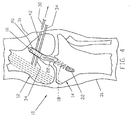
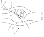
- a human knee joint 10 including a femur 12 and tibia 14, has been provided with an appropriate femoral bone tunnel 16 and an appropriate tibial bone tunnel 18.
- Such tunnels may be provided in ways well known in the art.
- a bone block 20, having ligament material 22 attached thereto, has been positioned in femoral tunnel 16. Such bone block positioning may also be achieved in ways well known in the art.
- a first metal wire 30, which may be of the type commonly referred to as a guidewire or a "K-wire" is advanced through skin 31 and a first portion 32 of femur 12.
- First wire 30 is advanced transversely of femoral tunnel 16 so as to intersect and extend through bone block 20, as shown in Fig. 2.
- a second metal wire 34 is advanced through a second portion 36 of femur 12.
- Second wire 34 is also advanced transversely of femoral tunnel 16 so as to also intersect and extend through bone block 20 (Fig. 3). At this point, bone block 20 is securely held in femoral tunnel 16 by the two spaced-apart metal wires 30, 34.
- one of the two wires 30, 34 is then removed, while the other of the two wires 30, 34 is left in place in femur 12 and bone block 20.
- wire 30 may be removed while wire 34 is left in place.
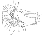
- a first absorbable rod 40 (Fig. 5) is then advanced through the bore 42 left by the removal of first wire 30, such that first absorbable rod 40 extends through femur 12 and bone block 20 (Fig. 6). At this point, bone block 20 is securely held in femoral tunnel 16 by both metal wire 34 and first absorbable rod 40.
- the absorbable rods 40, 44 may be made out of a material such as polylactic acid (PLA), polyglycolic acid (PGA), polydiaxanone (PDS), or out of some other such material which is formable into a relatively rigid and hard configuration, but which is absorbable by the body of the patient over time. If desired, the distal ends of absorbable rods 40, 44 can be pointed or rounded so as to facilitate their deployment into the body.
- PLA polylactic acid
- PGA polyglycolic acid
- PDS polydiaxanone
- a bone block is fixed within a bone tunnel, such that the bone block is anchored in the tunnel by cross-pins which are made out of a material which is absorbable by the body over time.
- the method may be exercised with any reasonable number of wires, exceeding one.
- the method includes the steps of placing the bone block in the bone tunnel, and then advancing a plurality of metal wires through the bone, transversely of the tunnel, so as to intercept the bone block and extend therethrough. At least one of the wires is then removed while leaving at least one of the wires in place, and that at least one removed wire is then replaced by at least one absorbable rod. At least one further of the wires is then removed and that at least one removed wire is then replaced by at least one further absorbable rod. The last-mentioned step is then repeated until a selected number of the metal wires is each replaced with an absorbable rod, whereby to retain the bone block in the bone tunnel with absorbable rods.
- Figs. 1-9 show metal wires 30, 34 and absorbable rods 40, 44 passing completely through bone block 20 during the cross-pinning procedure, it is also possible for metal wires 30, 34 and absorbable rods 40, 44 to pass only part way across bone block 20, if the same should be desired.
- various drill guides have been developed for forming transverse passages through the femur and bone block so as to cross-pin the bone block within the femoral tunnel.
- inventive method of the present invention may be practiced using such known drill guides.
- present invention may also be practiced using a novel rack assembly formed in accordance with the present invention.
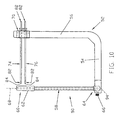
- Rack assembly 50 comprises an L-shaped member 52 having a base portion 54 and an arm portion 56.
- the arm portion 56 extends transversely, and preferably is normal to, base portion 54.
- Rack assembly 50 also includes a cannulated sleeve 58 which, at a first end 60 thereof, is provided with an enlarged head portion 62, and which, at a second end 64 thereof, is releasably connectable to base portion 54 of L-shaped member 52.
- Sleeve 58 may be retained in a bore 65 (Fig. 11) formed in base portion 54 by a set screw 66.
- a trocar sleeve guide member 70 is removably connectable to arm portion 56 of L-shaped member 52.
- Trocar sleeve guide member 70 is provided with bores 72 extending therethrough. Bores 72 extend substantially normal to a longitudinal axis 68 (Fig. 10) of the enlarged head portion 62 of cannulated sleeve 58.
- a set screw 71 (Fig. 11) may be used to releasably retain trocar sleeve guide member 70 in position on arm portion 56.
- arm portion 56 may be provided with stop means (not shown) for limiting the movement of the trocar sleeve guide member 70 along arm portion 56.
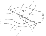
- Trocar sleeve guide member 70 is preferably formed in two halves releasably held together by a set screw 73 (Fig. 11), whereby trocar sleeve guide member 70 can be slidably mounted on, or detached from, trocar sleeves 74, 76 passing through bores 72, as will hereinafter be discussed.
- First and second trocar sleeves 74, 76 are slidably received by bores 72, such that sleeves 74, 76 are axially and rotatably movable in bores 72.
- trocar sleeve 74 is provided with a collar portion 78 having a slot 80 formed therein.
- Sleeve 76 is substantially identical to sleeve 74.
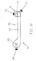
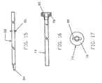
- Rack assembly 50 also includes one or more trocars 82 (Figs. 10 and 15) for disposition in the sleeves 74, 76.
- Each trocar 82 is provided with a sharp end 84 (Fig. 15) for penetration of bone.
- a transversely-extending pin 86 is provided near (but spaced from) the opposite end of the trocar 82. Pin 86 is fixed in place and is receivable by the slots 80 of trocar sleeves 74, 76 such that axial (in a distal direction) and rotational movement of trocar 82 causes similar movement of sleeves 74, 76.
- the first and second absorbable rods 40, 44 are slidable through sleeves 74, 76, as will be further described hereinbelow.
- Figs. 18-28 illustrate how rack assembly 50 may be used.
- FIG. 18 there is shown a human knee joint 10 including femur 12 and tibia 14.
- An appropriate femoral tunnel 16 and an appropriate tibial tunnel 18 have been provided, as by means and methods well known in the art.
- a guidewire 90 extends through the bone tunnels 16, 18 as shown.
- the rack assembly's cannulated sleeve 58 is fed over guidewire 90, through tibial tunnel 18 and into femoral tunnel 16, until the cannulated sleeve's head portion 62 engages an annular shoulder 92 in femoral tunnel 16 (Fig. 19).
- guidewire 90 extends through a bore 94 (Figs. 10 and 19) formed in base portion 54 of L-shaped member 52.
- the cannulated sleeve's head portion 62 is preferably sized so as to form a snug fit in femoral tunnel 16.
- Cannulated sleeve 58 may be positioned in the bone tunnels 16, 18 and then connected to L-shaped member 52 or, more preferably, cannulated sleeve 58 may be first connected to L-shaped member 52 and then positioned in femur 12 and tibia 14. Trocar sleeve guide member 70, if not already positioned on arm portion 56, is then fixed to arm portion 56, as by set screw 71 (Fig. 11).
- First trocar sleeve 74 is then inserted in a bore 72 of guide member 70 (Fig. 20), and trocar 82 is extended through sleeve 74 until pin 86 (Fig. 15) of trocar 82 is nested in slot 80 (Figs. 16 and 17) of sleeve 74, with the trocar's sharp end 84 extending beyond the distal end of sleeve 74 (Fig. 20).
- trocar 82 may be mounted in first trocar sleeve 74 before first trocar sleeve 74 is mounted in a bore 72.
- the combination of trocar sleeve 74 and trocar 82 is then drilled, as a unit, into femur 12 toward, but short of, the enlarged head portion 62 of cannulated sleeve 58 (Fig. 20).
- Trocar 82 may then be withdrawn from first trocar sleeve 74 and placed in second trocar sleeve 76 (Fig. 21).
- a second trocar 82 may be provided for second trocar sleeve 76.
- the combination of trocar sleeve 76 and trocar 82 is then drilled, as a unit, into femur 12 toward, but short of, head portion 62 of cannulated sleeve 58.
- the rack's L-shaped member 52 may then be removed from the surgical site. This may be accomplished by first loosening set screw 73 (Fig.
- trocar sleeves 74, 76 will be freed from guide member 70, and then sliding cannulated sleeve 58 downward along guidewire 90 until the cannulated sleeve emerges from bone tunnels 16, 18. This procedure will leave trocar sleeves 74, 76 lodged in femur 12 (Fig. 22).
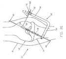
- Guidewire 90 is then used to pull a suture 96, which is attached to bone block 20, up through tibial tunnel 18 and into femoral tunnel 16, until bone block 20 engages the annular shoulder 92 in femoral tunnel 16 (Fig. 23).
- Guidewire 90 may be provided with an eyelet (not shown) adjacent to its proximal end so as to facilitate this procedure. Bone block 20 can then be held is this position by maintaining tension on the portion of suture 96 emerging from the top of femur 12.
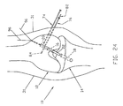
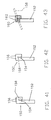
- Trocar sleeve 76 and trocar 82 are then drilled through bone block 20, as shown in Fig. 24.
- Trocar 82 may then be removed from sleeve 76, placed in sleeve 74, and sleeve 74 and trocar 82 drilled through bone block 20, as shown in Fig. 25.
- the trocar 82 (or trocars 82 if more than one trocar is used) may then be withdrawn from the sleeve 74 (or sleeves 74, 76).
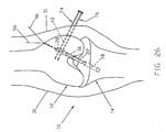
- the first absorbable rod 40 is then inserted, by sliding rod 40 through trocar sleeve 74 into a position extending through bone block 20 (Fig. 26).
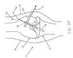
- Sleeve 74 may then be withdrawn from bone block 20 and femur 12, leaving first absorbable rod 40 in place in femur 12 and extending through bone block 20, as shown in Fig. 27.
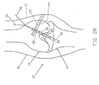
- second absorbable rod 44 is then slid into place through sleeve 76.
- Sleeve 76 is then removed, leaving second absorbable rod 44, along with first absorbable rod 40, extending through bone block 20 so as to lock bone block 20 in place in femoral tunnel 16, as shown in Fig. 28.
- rack assembly 50 with a guide member 70 which is not formed in two separable halves.
- guide member 70 can simply be detached from L-shaped member 52 by unscrewing set screw 71.
- Guide member 70 can then be left mounted on the outboard portions of sleeves 74, 76 until sleeves 74, 76 are withdrawn from the surgical site, with guide member 70 being removed with the last of the sleeves 74, 76.
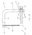
- Rack assembly 100 comprises an L-shaped member 102 having a base portion 104 and an arm portion 106. Arm portion 106 extends transversely of, and preferably is normal to, base portion 104.
- Rack assembly 100 also includes a cannulated sleeve 108 which, at a base end 110 thereof, is connected to base portion 104.
- Cannulated sleeve 108 may be retained in a bore 112 in base portion 104, as by screw threads or a set screw (not shown) or a press fit or the like.
- Cannulated sleeve 108 is provided with a slot (Fig. 29) extending substantially throughout the length of sleeve 108.
- Base portion 104 of L-shaped member 102 is also provided with a slot 116 (Fig. 30) which is alignable with the sleeve's slot 114 so as to place the slots 114, 116 in communication with each other.
- a trocar sleeve guide member 120 is removably connectable to arm portion 106 of L-shaped member 102.
- Trocar sleeve guide member 120 is provided with bores 122 extending therethrough. Bores 122 extend substantially normal to a hypothetical extension of the longitudinal axis 124 of cannulated sleeve 108.
- a set screw 126 (Fig. 30) may be used to releasably retain trocar sleeve guide member 120 in position on arm portion 106.
- arm portion 106 may be provided with a stop means (not shown) for limiting movement of member 120 on arm portion 106.
- Trocar sleeve guide member 120 is preferably formed in two halves releasably held together by a set screw 127 (Fig. 30), whereby trocar sleeve guide member 120 can be slidably mounted on, or detachable from, trocar sleeves 128, 130 passing through bores 122, as will hereinafter be discussed.
- First and second trocar sleeves 128, 130 are received by bores 122, such that sleeves 128, 130 are axially and rotatably movable in bores 122.
- the two trocar sleeves 128, 130 are substantially identical to the sleeve 74 shown in Figs. 16 and 17.
- Rack assembly 100 also includes one or more trocars 132 for disposition in sleeves 128, 130.
- the trocar 132 is substantially identical to the trocar 82 shown in Fig. 15.
- the aforementioned first and second absorbable rods 40, 44 are slidable through sleeves 128, 130.
- Figs. 34-40 illustrate how rack assembly 100 may be used to practice the present invention.
- a guidewire 90 extends through bone tunnels 16, 18.
- Guidewire 90 is then used to pull a suture 96, which is attached to bone block 20, up through tibial tunnel 18 and into femoral tunnel 16, such that bone block 20 is in engagement with annular shoulder 92 (Fig. 35). Bone block 20 is kept in this position by maintaining tension on the portion of suture 96 emerging from the top of femur 12.
- Suture 96 is then introduced into the rack assembly's cannulated sleeve 108 and base portion 104 by way of slots 114, 116.
- Cannulated sleeve 108 is then passed down the hole 133 (Figs. 35 and 36) left by the removed guidewire 90 until the distal end of the cannulated sleeve engages the top end of bone block 20 (Fig. 36).
- first trocar sleeve 128 is extended through a guide member bore 122 and a trocar 132 is inserted into sleeve 128.
- a trocar 132 may be inserted into first trocar sleeve 128 before first trocar sleeve 128 is inserted into a guide member bore 122.
- sleeve 128 and trocar 132 are then drilled, as a unit, into femur 12. With bone block 20 held against shoulder 92 by pulling on suture 96, the combination of sleeve 128 and trocar 132 is drilled through bone block 20 (Fig. 36). In a similar manner, sleeve 130 and trocar 132 (either the same trocar used with sleeve 128 or another trocar) are then drilled through bone block 20, as shown in Fig. 37.
- L-shaped member 102 and cannulated sleeve 108 are then removed from the surgical site. This may be accomplished by first loosening set screw 127 (Fig. 30) so as to separate trocar sleeve guide member 120 into its two halves, whereby trocar sleeves 128, 130 will be freed from guide member 120, and then sliding cannulated sleeve 108 upward and out of hole 133. Any trocars 132 are then removed, leaving the trocar sleeves 128, 130 extending into femur 12 and across bone block 20, as shown in Fig. 38.
- Second absorbable rod 44 is then slid through sleeve 130 and sleeve 130 removed (Fig. 39), and first absorbable rod 40 is slid through sleeve 128 and sleeve 128 removed, leaving absorbable rods 40, 44 in place (Fig. 40) holding bone block 20 locked in femoral tunnel 16.
- Suture 96 is then slipped through bone block 20 and removed, in the manner well known in the art.
- the present invention is by no means limited to the application thereof as herein disclosed and/or as shown in the drawings.
- inventive apparatus is described herein and illustrated with reference to the human knee joint. It is foreseen that the apparatus described herein will be particularly beneficial with respect to such operations. However, it will also be appreciated by those skilled in the art that the apparatus described herein find utility with respect to mammals generally, and with respect to other bones as, for example, in shoulder joints or the like.
- trocars 82 and 132 and their associated sleeves 74, 76 and 128, 130 might be passed only part way through bone block 20, but not all the way through; or sleeves 74, 76 and/or sleeves 128, 130 might be stopped short of bone block 20 while trocars 82 and/or 132 penetrate into bone block 20.
- trocars 82 and 132 are disclosed herein as being in the form of a hard rod with a sharp tip for penetrating bone.
- trocars 82 and 132 might comprise guidewires or K-wires with a pyramidal front point.
- the invention might also be practiced with trocars 82 and 132 comprising a twist drill, a spade drill and/or some other sort of drill.
- trocars 82 and/or 132 might be used with their associated rack assemblies 50 and 100, respectively, but without their associated sleeves 74, 76 and 128, 130, respectively. In this case, at least one trocar would always remain positioned in bone block 20 until at least one absorbable rod 40, 44 was positioned in the bone block.
- the present invention could also be practiced using just one sleeve 74 and one trocar 82, or just one sleeve 76 and one trocar 82; and it is possible to practice the invention using just one sleeve 128 and one trocar 132, or just one sleeve 130 and one trocar 132.
- the sleeve element would serve to retain the bone block in position within the bone tunnel while the trocar is replaced by the rod which will ultimately hold the bone block to the bone.
- the present application will have utility with respect to setting cross-pins which may not necessarily be absorbable.
- the present invention will have utility wherever cross-pinning needs to be achieved for cross-pins which cannot be passed directly through the bone and/or bone block, e.g., where the cross-pins may be too soft or too brittle or too fragile to pass directly through the bone and/or bone block, or where the cross-pins may have a geometry which makes it difficult or impossible for them to be passed directly through the bone and/or bone block.
- the present invention might be used to set cross-pins made out of plastic and/or ceramic materials, or the present invention might be used to set cross-pins made out of metal.
- a portion of the piece of tissue alone may be cross-pinned in a bone tunnel by any of the methods discussed above.
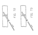
- the portion 150 of the piece of tissue 152 to be cross-pinned in the bone tunnel is preferably folded back upon itself one or more times.
- tacking stitches 154 may be used to hold the layers 156 of folded tissue together while the resulting mass 150 is inserted or pulled into the bone tunnel in a manner similar to the procedures used to locate a bone block in a bone tunnel discussed above.
- cross-pinning proceeds substantially as discussed above, such that the rods 158 ultimately extend either through the tissue mass (see phantom lines in Fig. 41), or between the folded tissue layers (see phantom lines in Fig. 42), or both.
- the chances of the rod and/or sleeve and/or trocar tearing laterally out of, or longitudinally along, the tissue 152 may be significant. This is particularly the case in those instances wherein the repair is to be subjected to substantial stress prior to complete healing. Accordingly, it is often desirable to reinforce the portion 150 of the tissue 152 to be cross-pinned within the bone tunnel. This may be accomplished in numerous ways well known to those skilled in the art. One such alternative, representatively shown in Fig. 43, is to "whip stitch" the portion 150 of the tissue 152 which is to be cross-pinned within the bone tunnel.
- the foregoing procedures may also be used to secure artifical grafts in the bone tunnel, i.e., grafts comprising an artifical prosthetic device not harvested from the body.
- it may or may not be desirable to fold the graft back upon itself one or more times, in the manner shown in Figs. 41-43, prior to cross-pinning.
- a portion 150 of a piece of tissue 152 may be fixed in a bone tunnel by positioning a bio-absorbable rod 163 diametrically across the bone tunnel 164, and thereafter pulling the portion 150 of the piece of tissue 152 into an open end of the bone tunnel, around the rod 163 and back out the same open end of the bone tunnel. More particularly, as best seen in Figs. 44-51, it has been found that the positioning of a bio-absorbable rod 163 diametrically across bone tunnel 164 is best accomplished with a trocar/sleeve combination 171 such as that illustratively shown in Figs. 15-17.
- a trocar/sleeve combination 171 be drilled in the manner discussed in detail above into bone 166, transversely to the longitudinal axis 172 (Fig. 44) of bone tunnel 164, diametrically through bone tunnel 164, and into bone 166 on the opposite side of bone tunnel 164 (see Figs. 44 and 45).
- the trocar 171a is removed from sleeve 171b, and a bio-absorbable rod 163 is inserted into sleeve 171a so as to occupy a position extending across bone tunnel 164 (see Figs. 96-48).
- Sleeve 171b is then removed from bone 166 and rod 163, leaving rod 163 extending from opening 168, diametrically across bone tunnel 164 and into opening 170 (see Fig. 49).
- one end 175 of a length of cord-like material, such as suture 173, is secured to an end 174 of piece of tissue 152 (Fig. 50).
- the other end 176 of the length of cord-like material 173 is then threaded into an open end 178 of bone tunnel 164, and thence around rod 163, and then back out open end 178 of bone tunnel 164 (see Fig. 50).
- the free end 176 of the cord-like material 173 is pulled so as to draw portion 150 of piece of tissue 152 into open end 178 of bone tunnel 164, around bio-absorbable rod 163, and back out open end 178 of bone tunnel 164.
- Tissue portion 150 thus assumes a generally U-shape, having its closed end slidably secured in bone tunnel 164 by bio-absorbable rod 163, and its free ends extending outwardly from the same open end 178 of bone tunnel 164 (see Fig. 51).
- the foregoing procedure may also be used to secure articial grafts in the bone tunnel, i.e., grafts comprising an artificial prosthetic device not harvested from the body.
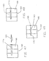
- bone blocks are relatively hard. This is frequently the case where the bone block is formed out of cortical bone.
- the bone block may fracture, as shown, for example, in Figs. 52 and 53.
- the possibility of bone block fracture may be reduced by reducing the diameter of the trocar/sleeve combination, and hence the resulting hole through the bone block, but this may in turn lead to an increase in the possibility of rod breakage when a load is applied to the graft ligament.
- the solution utilizes the facts that (1) a bone block is significantly stronger in compression than it is in tension, and (2) a larger diameter rod will provide a stronger bone block fixation in a bone tunnel if bone block fracture is not an issue.
- the bone block 200 is located at substantially closed end 202 of substantially blind bone tunnel 204, with its associated tissue graft 206 extending outwardly from the open end 208 of the substantially blind bone tunnel 204.
- a guide hole 201 may extend through substantially closed end 202 of bone tunnel 204 so as to allow bone block 200 to be drawn into bone tunnel 204 by a cord-like element 203, or otherwise located in bone tunnel 204 as discussed hereinabove.
- a rod 208 is then located diametrically across bone tunnel 204 adjacent to proximal end 210 of bone block 200.
- rod 208 is positioned utilizing the same method as described above with regard to the threading of a portion of a piece of tissue over a rod extending diametrically through a bone tunnel (see Figs. 44-51).
- the rod 208 may pass through the tissue graft 208, or not, as desired. The result is that bone block 200 is reliably fixed in bone tunnel 206 between substantially closed tunnel end 202 and rod 208.
- the second of the above-mentioned alternatives proceeds from the premise that if the sleeve does not have to extend into or through the bone block, a significantly larger diameter rod may be used with a corresponding increase in the strength of the fixation of the bone block in the bone tunnel.
- This alternative is representatively shown in Figs. 56-63, which will be referred to specifically below.
- the trocar/sleeve combinations 210 are drilled through the skin and into the bone in the same manner as discussed in detail above, and the bone block is located in the bone tunnel such that the various elements reside in a configuration generally as depicted in Fig. 22.
- the trocars are disengaged from the sleeves, the bone block is pulled up into the bone tunnel (Fig. 23), and rods are inserted through (i) the sleeves and (ii) the bone located between the distal ends of the sleeves and the bone tunnel, and then into the bone block.
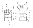
- a second, longer trocar 212a, 212b may be inserted into each of the sleeves 214a, 214b and either drilled (Fig. 57) or tapped (Fig. 58) through the bone 216 located between the distal ends 218a, 218b of the sleeves 214a, 214b, and then into the bone tunnel 220 and into the bone block 222.
- one of the longer trocars 212 is removed (Fig. 59), and a metal, plastic, ceramic or bio-absorbable rod 224a is inserted into the bone and the bone block through the sleeve (Fig. 60).
- a metal, plastic, ceramic or bio-absorbable rod 224a is inserted into the bone and the bone block through the sleeve (Fig. 60).
- the removal of the other longer trocar 212 Fig. 61
- the insertion of another rod 224b into the bone and bone block through the second sleeve Fig. 62
- the sleeves are removed from the patient (Fig
- the longer trocars 212a and 212b are commonly stepped, e.g., in the manner shown in Fig. 64. More particularly, the longer trocars 212a commonly include a distal portion 230 having a smaller transverse cross-sectional diameter than their proximal portion 232, and define a distally-facing radial shoulder 234 at the joiner of their proximal and distal portions. In this way, the extent of trocar penetration beyond the distal ends of the sleeves is controlled by pre-selecting the axial length of the distal portion of the longer trocars.
- the longer trocars are allowed to penetrate beyond the distal ends of the sleeves only to the point at which their distally-facing radial shoulders engage either the bone at the distal ends of the sleeves, or a radially-disposed, inward projection 236 formed on the sleeve side wall (Fig. 65).
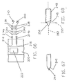
- rigid rods 224a, 224b may be driven through the sleeves 214a, 214b, through the bone 216 located between the sleeves and the bone tunnel 220, and then into the bone block 222 directly. This may be accomplished by, preferably, pointing or rounding the distal ends of the rods 224a, 224b, inserting the rods into the sleeves 214a, 214b, and using a plunger shaft 238 and tapping means 240 to drive the rods into position through the bone and into the bone block (Fig. 66) .
- the radial shoulder 242 (Fig. 55), formed by the distal end of the sleeve proximally of the pointed distal end 224 of the trocar extending distally thereof, can be a significant impediment to the passage of the interlocked trocar/sleeve combination into bone.
- this shoulder while normally only about .005 to .010 inch in radial thickness, has been noted to cause burning of the bone as the trocar/sleeve combination is advanced through the bone toward the bone tunnel.
- the distal edge 242 of the sleeve could be bevelled at an angle substantially equal to that of the adjacent trocar point 244 (see Fig. 67).
- This is not preferred, however, in view of the variations in machining tolerance commonly acceptable in the art in the formation of bevelled edges and trocar points.
- the chance of an exact mating of the trocar point with a bevelled sleeve end is unlikely.
- the bone burning problem and more generally the problem of the resistance to penetration of the trocar/sleeve combination into the bone, are still present in the embodiment shown in Fig. 67, albeit to a perhaps smaller degree than in the Fig. 55 embodiment.
- the distal end 246 of the sleeve 248 should be slanted at an angle of approximately 15° proximally relative to a plane 250 located normal to the longitudinal axis 252 of the sleeve (see Fig. 68).
- the trocar point 256 drills into the bone in the same manner as previously described, while the slanted distal end 246 of the sleeve 248 cuts into the sidewall of the hole formed by the trocar point, instead of rotating flat against the bone surrounding the hole being formed by the trocar.
- a bone drill which does not exhibit a tendency to bind, and/or to burn the bone during use is significantly more desirable than a bone drill which does bind or burn the bone during use.
- the angle of bevel of the sleeve must be substantially equal to the angle at which the distal drilling sharp end of the trocar is disposed relative to the longitudinal axis of the trocar.
- one preferred method of using the present invention includes the following steps:
- a flattened head 258 (Fig. 69) defining a window 260 therethrough might be used in place of the enlarged head 62.
- the flattened head 258 would extend substantially diametrically across the bone tunnel 262 in a plane transverse to an axial projection of the trocar/sleeve assemblies 264 being drilled into the bone.
- the window 260 would be so disposed that the trocar/sleeve assemblies (or the trocars alone) could penetrate into the bone tunnel, through the window 260 in the head of the cannulated sleeve 266, and then into the bone on the opposite side of the bone tunnel.
- this embodiment of the present invention is useful in any situation in which it is desired to form diametrically opposed openings in the sidewall of a bone tunnel.
- Particular examples of such situations include those wherein the length of the sleeve and the length, and rigidity, of the rods are such that they may be relied upon to ensure that a rod entering the bone tunnel from the drill means entry side thereof will be maintained in alignment with, and engage, the opening on the other side of the bone tunnel.
- a rigid rod is passed through an object in a bone tunnel may find this alternative beneficial.
- interlocking trocar/sleeve assemblies discussed hereinabove have numerous other uses beyond the cross-pinning of objects in bone tunnels.
- One such illustrative use is in the placement of absorbable, or non-absorbable, pins across bone fractures so as to assist in maintaining broken bones in a desired healing relationship after fracture reduction procedures have been completed.
- this method follows the now well-understood steps of drilling a trocar/sleeve assembly into the desired position in bone, removing the trocar, inserting a rod into the sleeve, and then removing the sleeve from the bone and the rod.
- Other illustrative uses of the devices and concepts of the present invention may include, among others, the removal of tissue from the interior of bones, and/or the delivery of other things into the interior of a bone, such as other devices or prostheses, drugs, bone graft material, substitute bone marrow, and so on.
Claims (12)
- Anordnung (50) aus Trokar (82) und Trokarhülse (74, 76) zur Verwendung beim Bilden von Durchgängen in einem Knochen (12), wobei die Anordnung (50) aufweist:einen Trokar (82) mit einer Welle, einem distalen scharfen Bohrende (84) und wenigstens einem Stift (86), der sich radial von der Welle an einer vorausgewählten Entfernung in Längsrichtung nahe dem distalen scharfen Ende (84) erstreckt; undeine Trokarhülse (74, 76) mit einem distalen Ende und einem proximalen Ende, wobei die Hülse eine Längsbohrung definiert, die sich zwischen dem distalen Ende und dem proximalen Ende erstreckt, und wenigstens einem Längsschlitz (80) in einer Seitenwand der Bohrung, der sich von dem proximalen Ende der Hülse (74, 76) zu einem geschlossenen distalen Ende des Schlitzes erstreckt, das sich an einer vorausgewählten Längsentfernung nahe dem distalen Ende der Hülse (74, 76) befindet;wobei das distale Ende der Hülse (74, 76) von einer inneren Kante zu einer äußeren Kante unter einem Winkel relativ zu der Längsachse der Hülse (74, 76) abgeschrägt ist, wobei der Winkel im wesentlichen gleich einem Winkel ist, unter dem das distale scharfe Bohrende (84) relativ zu der Längsachse des Trokars (82) angeordnet ist,wobei der Trokar (82) dazu ausgelegt ist, verschiebbar in der Bohrung der Hülse (74, 76) zu liegen, wobei der wenigstens eine Stift (86) gleitend in den wenigstens einen Längsschlitz greift, und die vorausgewählte Entfernung in Längsrichtung derart ist, daß, wenn der wenigstens eine radiale Stift (86) an dem geschlossenen Ende des wenigstens einen Längsschlitzes (80) anliegt, das distale scharfe Bohrende (84) des Trokars (82) distal vom distalen Ende der Hülse (74, 76) hervorsteht;wodurch der Trokar (82) und die Trokarhülse (74, 76) für die integrale Dreh- und distal gerichtete Längsbewegung lösbar miteinander verbunden sind.
- Anordnung (50) nach Anspruch 1, bei der das distale Ende der Hülse (74, 76) in einer Ebene angeordnet ist, die sich an einem distal spitzen Winkel von ungefähr 15° zu der Längsachse der Hülse (74, 76) befindet, und das distale scharfe Bohrende des Trokars, wenn es vollständig im Eingriff mit der Hülse ist, sich distal zum am weitestens distal liegenden Teil des distalen Endes der Hülse (74, 76) erstreckt.
- Anordnung (50) nach Anspruch 1, weiterhin mit einem zweiten Trokar (82) zur Verwendung im Austausch gegen den Trokar (82), nachdem die Anordnung (50) aus Trokar (82) und Trokarhülse (74, 76) in dem Knochen (12) angeordnet ist, wobei der zweite Trokar (82) einen distalen Teil mit einem ersten Querschnitt, einen proximalen Teil mit einem zweiten Querschnitt, wobei der zweite Querschnitt größer ist als der erste Querschnitt, und eine distal gewandte Schulter an einem Verbindungsbereich des distalen Teiles und des proximalen Teiles hat, wobei die Schulter so ausgelegt ist, daß sie an dem Knochen (12) an dem distalen Ende der Hülse (74, 76) anliegt, wenn der zweite Trokar (82) in den Knochen durch die Hülse (74, 76) vorbewegt wird, um so die Tiefe des Eindringens des zweiten Trokars (82) in den Knochen (12) zu begrenzen.
- Anordnung (50) nach Anspruch 1, bei der die Bohrung der Trokarhülse einen im wesentlichen zylindrischen Längsdurchgang zwischen dem proximalen Ende und dem distalen Ende definiert, wobei der wenigstens eine Schlitz ein Paar gegenüberliegender Schlitze (80) aufweist und das geschlossene distale Ende der Hülse gegenüberliegende geschlossene Enden aufweist, die von dem distalen Ende der Hülse beabstandet sind; und
das scharfe Bohrende (84) des Trokars zum Bohren in den Knochen ausgelegt ist und der wenigstens eine Stift ein Paar gegenüberliegende Stifte (86) aufweist, die dazu ausgelegt sind, schiebbar in jeweils den Schlitzen (80) aufgenommen zu werden, wenn die Welle sich in der Bohrung befindet, so daß der Vorsprung des scharfen distalen Endes (84) des Trokars aus dem distalen Ende der Hülse hinaus entsprechend der Längsentfernung zwischen dem scharfen distalen Bohrende (84) des Trokars und den Stiften (86) in bezug auf den Längsabstand der geschlossenen Enden (80) des Schlitzes von dem distalen Ende zu dem Trokar (82) begrenzt ist;
wobei der Trokar (82) in die Bohrung derart einsetzbar ist, daß sich die ergebende Kombination aus Trokar (82) und Trokarhülse (74, 76) gedreht und distal in den Knochen (12) als eine Einheit gebohrt werden kann und der Trokar (82) proximal in die Hülse (74, 76) einschiebbar und aus dieser entfernbar ist;
wobei ein Element (40, 44) in den Knochen (12) durch die Bohrung der Hülse (74, 76) einsetzbar ist; und
die Hülse (74, 76) aus dem Element (40, 44) und dem Knochen (12) entfernbar ist. - Anordnung nach Anspruch 4, weiter mit:einem zweiten Trokar (82), der einen distalen Teil mit einem ersten Querschnitt und einen proximalen Teil mit einem zweiten Querschnitt, wobei der erste Querschnitt kleiner ist als der zweite Querschnitt, und eine distal weisenden Schulter an einem Verbindungsbereich des ersten und zweiten Querschnitts umfaßt;wobei die Schulter dazu ausgelegt ist, an dem Knochen (12) an dem distalen Ende der Hülse (74, 76) anzuliegen.
- Anordnung (50) nach Anspruch 5, bei der der Längsdurchgang durch die Hülse (74, 76) ein internes Stoppmittel umfaßt, das dazu ausgelegt ist, an der Schulter des Trokar anzuliegen, um so weiter die Längsbewegung des zweiten Trokars (82) durch die Hülse (74, 76) und in den Knochen (12) an dem distalen Ende der Hülse (74, 76) zu begrenzen.
- Anordnung (50) nach Anspruch 5, bei der der Knochen (12) einen Knochentunnel (16) definiert, wobei die Kombination aus Trokar (82) und Trokarhülse (74, 76) dazu ausgelegt ist, in den Knochen (12) quer zum Knochentunnel (16), jedoch nicht in den Knochentunnel (16) einzudringen, wobei ein Knochenblock (20) in dem Knochentunnel (16) in axialer Ausrichtung mit der Kombination aus Trokar (82) und Trokarhülse (74, 76) angeordnet ist und der zweite Trokar (82) so ausgelegt ist, daß er durch den Knochen (12) zwischen dem distalen Ende der Hülse (74, 76) und dem Knochentunnel (60) und in den Knochenblock (20) dringt, und das Element eine Stange (40) aufweist.
- Anordnung nach Anspruch 5, bei dem das Element aus der Gruppe bestehend aus im wesentlichen starren Stangen, medizinischen Verabreichungen, prosthetischen Materialien und Ersatzgewebe ausgewählt ist.
- Anordnung nach Anspruch 7, bei der die Stange (20) aus bioabsorbierbarem Material gebildet ist.
- Anordnung nach Anspruch 1, bei der das bioabsorbierbare Material aus der Gruppe bestehend aus Polymilchsäure, Polyglykolsäure und Polydiaxanon ausgewählt ist.
- Anordnung (50) nach Anspruch 7, bei der die Stange (40) aus einem Material ausgewählt aus der Gruppe bestehend aus im wesentlichen starren Metallen, Kunststoffen und Keramiken gebildet ist.
- Anordnung (50) nach Anspruch 7, bei der der zweite Trokar (82) dazu ausgelegt ist, durch den Knochenblock (20) und zurück in den Knochen (12) zu dringen.
Priority Applications (2)
| Application Number | Priority Date | Filing Date | Title |
|---|---|---|---|
| EP06076794A EP1759644B1 (de) | 1998-01-28 | 1999-01-27 | Vorrichtung zur Befestigung eines Transplantates in einem Knochentunnel |
| EP10075186A EP2213253B1 (de) | 1998-01-28 | 1999-01-27 | Vorrichtung zur Befestigung eines Transplantates in einem Knochentunnel |
Applications Claiming Priority (2)
| Application Number | Priority Date | Filing Date | Title |
|---|---|---|---|
| US14937 | 1998-01-28 | ||
| US09/014,937 US6113604A (en) | 1997-01-14 | 1998-01-28 | Method and apparatus for fixing a graft in a bone tunnel |
Related Child Applications (1)
| Application Number | Title | Priority Date | Filing Date |
|---|---|---|---|
| EP06076794A Division EP1759644B1 (de) | 1998-01-28 | 1999-01-27 | Vorrichtung zur Befestigung eines Transplantates in einem Knochentunnel |
Publications (3)
| Publication Number | Publication Date |
|---|---|
| EP0933064A2 EP0933064A2 (de) | 1999-08-04 |
| EP0933064A3 EP0933064A3 (de) | 2000-07-05 |
| EP0933064B1 true EP0933064B1 (de) | 2006-10-11 |
Family
ID=21768661
Family Applications (3)
| Application Number | Title | Priority Date | Filing Date |
|---|---|---|---|
| EP99300598A Expired - Lifetime EP0933064B1 (de) | 1998-01-28 | 1999-01-27 | Vorrichtung zur Befestigung eines Transplantates in einem Knochentunnel |
| EP10075186A Expired - Lifetime EP2213253B1 (de) | 1998-01-28 | 1999-01-27 | Vorrichtung zur Befestigung eines Transplantates in einem Knochentunnel |
| EP06076794A Expired - Lifetime EP1759644B1 (de) | 1998-01-28 | 1999-01-27 | Vorrichtung zur Befestigung eines Transplantates in einem Knochentunnel |
Family Applications After (2)
| Application Number | Title | Priority Date | Filing Date |
|---|---|---|---|
| EP10075186A Expired - Lifetime EP2213253B1 (de) | 1998-01-28 | 1999-01-27 | Vorrichtung zur Befestigung eines Transplantates in einem Knochentunnel |
| EP06076794A Expired - Lifetime EP1759644B1 (de) | 1998-01-28 | 1999-01-27 | Vorrichtung zur Befestigung eines Transplantates in einem Knochentunnel |
Country Status (6)
| Country | Link |
|---|---|
| US (3) | US6113604A (de) |
| EP (3) | EP0933064B1 (de) |
| JP (2) | JPH11267135A (de) |
| AU (1) | AU762698B2 (de) |
| CA (1) | CA2260443C (de) |
| DE (2) | DE69942679D1 (de) |
Families Citing this family (120)
| Publication number | Priority date | Publication date | Assignee | Title |
|---|---|---|---|---|
| US8080058B2 (en) * | 2003-04-01 | 2011-12-20 | Depuy Mitek, Inc. | Method and apparatus for fixing a graft in a bone tunnel |
| US6066173A (en) * | 1998-01-28 | 2000-05-23 | Ethicon, Inc. | Method and apparatus for fixing a graft in a bone tunnel |
| US6752830B1 (en) | 1999-07-20 | 2004-06-22 | Ethicon, Inc. | Apparatus and method for reconstructing a ligament |
| WO2001010311A1 (en) * | 1999-08-10 | 2001-02-15 | Ethicon, Inc. | Apparatus and method for reconstructing a ligament |
| DE60026136T2 (de) * | 1999-11-15 | 2006-11-23 | Arthrex Inc., Naples | Verjüngende bioabsorbierende Interferenzschraube zur ostealen Befestigung von Bändern |
| US6325804B1 (en) * | 2000-06-28 | 2001-12-04 | Ethicon, Inc. | Method for fixing a graft in a bone tunnel |
| US6878166B2 (en) * | 2000-08-28 | 2005-04-12 | Ron Clark | Method and implant for securing ligament replacement into the knee |
| US7530999B2 (en) * | 2000-08-28 | 2009-05-12 | Biomet Sports Medicine, Llc | Method and implant for securing ligament replacement into the knee |
| AU2002225837B2 (en) * | 2000-10-25 | 2007-01-18 | Kyphon Sarl | Systems and methods for reducing fractured bone using a fracture reduction cannula |
| US7195642B2 (en) | 2001-03-13 | 2007-03-27 | Mckernan Daniel J | Method and apparatus for fixing a graft in a bone tunnel |
| US6517546B2 (en) | 2001-03-13 | 2003-02-11 | Gregory R. Whittaker | Method and apparatus for fixing a graft in a bone tunnel |
| US7594917B2 (en) | 2001-03-13 | 2009-09-29 | Ethicon, Inc. | Method and apparatus for fixing a graft in a bone tunnel |
| US20050065533A1 (en) * | 2001-05-31 | 2005-03-24 | Magen Hugh E. | Apparatus for assembling anterior cruciate ligament reconstruction system |
| KR100432513B1 (ko) * | 2001-09-11 | 2004-05-22 | 한국과학기술원 | 광여기 공정 장치 및 방법 |
| US6712849B2 (en) * | 2001-10-01 | 2004-03-30 | Scandius Biomedical, Inc. | Apparatus and method for reconstructing a ligament |
| US7520898B2 (en) * | 2001-10-01 | 2009-04-21 | Scandius Biomedical, Inc. | Apparatus and method for reconstructing a ligament |
| US20060206206A1 (en) | 2003-06-06 | 2006-09-14 | Peyman Gholam A | Intraocular telescope |
| US7713300B2 (en) * | 2002-01-31 | 2010-05-11 | Biomet Sports Medicince, LLC | Apparatus and method for manipulating a flexible strand and soft tissue replacement during surgery |
| US7033364B1 (en) * | 2002-01-31 | 2006-04-25 | Arthrotek, Inc. | Apparatus and method for manipulating a flexible strand and soft tissue replacement during surgery |
| AU2003226382A1 (en) * | 2002-04-12 | 2003-10-27 | Eric S. Steenlage | Method and apparatus for reconstructing a ligament |
| US7175632B2 (en) * | 2002-05-15 | 2007-02-13 | Linvatec Corporation | Cross-pin graft fixation instruments and method |
| US7338492B2 (en) * | 2002-05-15 | 2008-03-04 | Linvatec Corporation | Cross-pin graft fixation, instruments, and methods |
| US7678138B2 (en) * | 2002-05-15 | 2010-03-16 | Linvatec Corporation | Two piece cross-pin graft fixation |
| US7588595B2 (en) * | 2002-10-29 | 2009-09-15 | Stryker Endoscopy | Graft fixation device and method |
| US7491206B2 (en) * | 2003-06-27 | 2009-02-17 | Ethicon, Inc. | Adjustable drill guide assembly and method of use |
| US7896917B2 (en) | 2003-10-15 | 2011-03-01 | Biomet Sports Medicine, Llc | Method and apparatus for graft fixation |
| US7341592B1 (en) | 2003-10-15 | 2008-03-11 | Biomet Sports Medicine, Inc. | Method and apparatus for graft fixation |
| US7588588B2 (en) * | 2003-10-21 | 2009-09-15 | Innovative Spinal Technologies | System and method for stabilizing of internal structures |
| US7588575B2 (en) * | 2003-10-21 | 2009-09-15 | Innovative Spinal Technologies | Extension for use with stabilization systems for internal structures |
| US7967826B2 (en) | 2003-10-21 | 2011-06-28 | Theken Spine, Llc | Connector transfer tool for internal structure stabilization systems |
| US8088128B2 (en) | 2004-03-25 | 2012-01-03 | Depuy Mitek, Inc. | Implantable cross-pin for anterior cruciate ligament repair |
| DE102004018426A1 (de) * | 2004-04-07 | 2005-10-27 | Karl Storz Gmbh & Co.Kg | Instrumentarium zum Fixieren eines Implantates in einem Knochen |
| US8002778B1 (en) | 2004-06-28 | 2011-08-23 | Biomet Sports Medicine, Llc | Crosspin and method for inserting the same during soft ligament repair |
| US8118836B2 (en) | 2004-11-05 | 2012-02-21 | Biomet Sports Medicine, Llc | Method and apparatus for coupling soft tissue to a bone |
| US8303604B2 (en) | 2004-11-05 | 2012-11-06 | Biomet Sports Medicine, Llc | Soft tissue repair device and method |
| US7905904B2 (en) | 2006-02-03 | 2011-03-15 | Biomet Sports Medicine, Llc | Soft tissue repair device and associated methods |
| US7909851B2 (en) | 2006-02-03 | 2011-03-22 | Biomet Sports Medicine, Llc | Soft tissue repair device and associated methods |
| US9017381B2 (en) | 2007-04-10 | 2015-04-28 | Biomet Sports Medicine, Llc | Adjustable knotless loops |
| US8298262B2 (en) | 2006-02-03 | 2012-10-30 | Biomet Sports Medicine, Llc | Method for tissue fixation |
| US8361113B2 (en) | 2006-02-03 | 2013-01-29 | Biomet Sports Medicine, Llc | Method and apparatus for coupling soft tissue to a bone |
| US7749250B2 (en) | 2006-02-03 | 2010-07-06 | Biomet Sports Medicine, Llc | Soft tissue repair assembly and associated method |
| US8137382B2 (en) | 2004-11-05 | 2012-03-20 | Biomet Sports Medicine, Llc | Method and apparatus for coupling anatomical features |
| US9801708B2 (en) | 2004-11-05 | 2017-10-31 | Biomet Sports Medicine, Llc | Method and apparatus for coupling soft tissue to a bone |
| US8840645B2 (en) | 2004-11-05 | 2014-09-23 | Biomet Sports Medicine, Llc | Method and apparatus for coupling soft tissue to a bone |
| US8088130B2 (en) | 2006-02-03 | 2012-01-03 | Biomet Sports Medicine, Llc | Method and apparatus for coupling soft tissue to a bone |
| US7658751B2 (en) | 2006-09-29 | 2010-02-09 | Biomet Sports Medicine, Llc | Method for implanting soft tissue |
| US8128658B2 (en) | 2004-11-05 | 2012-03-06 | Biomet Sports Medicine, Llc | Method and apparatus for coupling soft tissue to bone |
| US8998949B2 (en) | 2004-11-09 | 2015-04-07 | Biomet Sports Medicine, Llc | Soft tissue conduit device |
| US7569061B2 (en) | 2004-11-16 | 2009-08-04 | Innovative Spinal Technologies, Inc. | Off-axis anchor guidance system |
| EP1871239B1 (de) * | 2005-04-20 | 2014-08-13 | Arthroscopic Innovations LLC | Nahtfixierungsvorrichtung für chirurgische reparaturen |
| US7833230B2 (en) * | 2005-04-20 | 2010-11-16 | Arthroscopic Innovations Llc | Method and apparatus for providing a passageway |
| FR2893836B1 (fr) * | 2005-11-29 | 2008-10-10 | Pierre Imbert | Implant chirurgical a appui extra cortical pour transplant ligamentaire |
| FR2893835B1 (fr) * | 2005-11-29 | 2008-10-10 | Pierre Imbert | Implant chirurgical a appui endo cortical pour le transplant ligamentaire |
| US11259792B2 (en) | 2006-02-03 | 2022-03-01 | Biomet Sports Medicine, Llc | Method and apparatus for coupling anatomical features |
| US9078644B2 (en) | 2006-09-29 | 2015-07-14 | Biomet Sports Medicine, Llc | Fracture fixation device |
| US8968364B2 (en) | 2006-02-03 | 2015-03-03 | Biomet Sports Medicine, Llc | Method and apparatus for fixation of an ACL graft |
| US10517587B2 (en) | 2006-02-03 | 2019-12-31 | Biomet Sports Medicine, Llc | Method and apparatus for forming a self-locking adjustable loop |
| US8251998B2 (en) | 2006-08-16 | 2012-08-28 | Biomet Sports Medicine, Llc | Chondral defect repair |
| US8597327B2 (en) | 2006-02-03 | 2013-12-03 | Biomet Manufacturing, Llc | Method and apparatus for sternal closure |
| US8771352B2 (en) | 2011-05-17 | 2014-07-08 | Biomet Sports Medicine, Llc | Method and apparatus for tibial fixation of an ACL graft |
| US8562647B2 (en) | 2006-09-29 | 2013-10-22 | Biomet Sports Medicine, Llc | Method and apparatus for securing soft tissue to bone |
| US8652171B2 (en) | 2006-02-03 | 2014-02-18 | Biomet Sports Medicine, Llc | Method and apparatus for soft tissue fixation |
| US8574235B2 (en) | 2006-02-03 | 2013-11-05 | Biomet Sports Medicine, Llc | Method for trochanteric reattachment |
| US8652172B2 (en) | 2006-02-03 | 2014-02-18 | Biomet Sports Medicine, Llc | Flexible anchors for tissue fixation |
| US9538998B2 (en) | 2006-02-03 | 2017-01-10 | Biomet Sports Medicine, Llc | Method and apparatus for fracture fixation |
| US8562645B2 (en) | 2006-09-29 | 2013-10-22 | Biomet Sports Medicine, Llc | Method and apparatus for forming a self-locking adjustable loop |
| US8801783B2 (en) | 2006-09-29 | 2014-08-12 | Biomet Sports Medicine, Llc | Prosthetic ligament system for knee joint |
| US8936621B2 (en) | 2006-02-03 | 2015-01-20 | Biomet Sports Medicine, Llc | Method and apparatus for forming a self-locking adjustable loop |
| US8506597B2 (en) | 2011-10-25 | 2013-08-13 | Biomet Sports Medicine, Llc | Method and apparatus for interosseous membrane reconstruction |
| US9149267B2 (en) | 2006-02-03 | 2015-10-06 | Biomet Sports Medicine, Llc | Method and apparatus for coupling soft tissue to a bone |
| US11311287B2 (en) | 2006-02-03 | 2022-04-26 | Biomet Sports Medicine, Llc | Method for tissue fixation |
| US9918826B2 (en) | 2006-09-29 | 2018-03-20 | Biomet Sports Medicine, Llc | Scaffold for spring ligament repair |
| US8672969B2 (en) | 2006-09-29 | 2014-03-18 | Biomet Sports Medicine, Llc | Fracture fixation device |
| US8500818B2 (en) | 2006-09-29 | 2013-08-06 | Biomet Manufacturing, Llc | Knee prosthesis assembly with ligament link |
| US11259794B2 (en) | 2006-09-29 | 2022-03-01 | Biomet Sports Medicine, Llc | Method for implanting soft tissue |
| US7942914B2 (en) * | 2006-10-17 | 2011-05-17 | Arthroscopic Innovations Llc | Method and apparatus for surgical repair |
| US9237916B2 (en) | 2006-12-15 | 2016-01-19 | Gmedeleware 2 Llc | Devices and methods for vertebrostenting |
| DE102006062382B4 (de) * | 2006-12-22 | 2014-08-07 | Karl Storz Gmbh & Co. Kg | Vorrichtung zum Führen eines Bohrwerkzeugs zum Einbringen einer zweiten Bohrung in einem Knochen |
| US8147546B2 (en) | 2007-03-13 | 2012-04-03 | Biomet Sports Medicine, Llc | Method and apparatus for graft fixation |
| WO2009155319A1 (en) | 2008-06-17 | 2009-12-23 | Soteira, Inc. | Devices and methods for fracture reduction |
| US8197489B2 (en) | 2008-06-27 | 2012-06-12 | Depuy Products, Inc. | Knee ligament balancer |
| AU2009222580B2 (en) * | 2008-10-10 | 2014-11-27 | Depuy Mitek, Inc. | Method for replacing a ligament in a knee |
| WO2010111246A1 (en) | 2009-03-23 | 2010-09-30 | Soteira, Inc. | Devices and methods for vertebrostenting |
| US8740817B2 (en) | 2009-03-31 | 2014-06-03 | Depuy (Ireland) | Device and method for determining forces of a patient's joint |
| US8556830B2 (en) | 2009-03-31 | 2013-10-15 | Depuy | Device and method for displaying joint force data |
| US8551023B2 (en) | 2009-03-31 | 2013-10-08 | Depuy (Ireland) | Device and method for determining force of a knee joint |
| US8597210B2 (en) | 2009-03-31 | 2013-12-03 | Depuy (Ireland) | System and method for displaying joint force data |
| US8721568B2 (en) * | 2009-03-31 | 2014-05-13 | Depuy (Ireland) | Method for performing an orthopaedic surgical procedure |
| US20100305710A1 (en) | 2009-05-28 | 2010-12-02 | Biomet Manufacturing Corp. | Knee Prosthesis |
| US20110118838A1 (en) * | 2009-11-16 | 2011-05-19 | George Delli-Santi | Graft pulley and methods of use |
| US8449612B2 (en) * | 2009-11-16 | 2013-05-28 | Arthrocare Corporation | Graft pulley and methods of use |
| US8679130B2 (en) | 2010-03-05 | 2014-03-25 | Biomet Manufacturing, Llc | Guide assembly for lateral implants and associated methods |
| US8419743B2 (en) | 2010-03-05 | 2013-04-16 | Biomet Manufacturing Corp. | Assembly tool for modular implants and associated method |
| US8460393B2 (en) | 2010-03-05 | 2013-06-11 | Biomet Manufacturing Corp. | Modular lateral hip augments |
| US8333807B2 (en) | 2010-03-05 | 2012-12-18 | Biomet Manufacturing Corp. | Method and apparatus for trialing and implanting a modular femoral hip |
| US8529569B2 (en) | 2010-03-05 | 2013-09-10 | Biomet Manufacturing, Llc | Method and apparatus for preparing a proximal femur |
| US8221432B2 (en) | 2010-03-05 | 2012-07-17 | Biomet Manufacturing Corp. | Method and apparatus for implanting a modular femoral hip |
| FR2958841B1 (fr) * | 2010-04-14 | 2012-05-18 | Pierre Imbert | Systeme ancillaire pour la pose d'un transplant ligamentaire a l'aide de broches |
| US8617176B2 (en) | 2011-08-24 | 2013-12-31 | Depuy Mitek, Llc | Cross pinning guide devices and methods |
| GB201115411D0 (en) | 2011-09-07 | 2011-10-19 | Depuy Ireland | Surgical instrument |
| US9357991B2 (en) | 2011-11-03 | 2016-06-07 | Biomet Sports Medicine, Llc | Method and apparatus for stitching tendons |
| US9314241B2 (en) | 2011-11-10 | 2016-04-19 | Biomet Sports Medicine, Llc | Apparatus for coupling soft tissue to a bone |
| US9370350B2 (en) | 2011-11-10 | 2016-06-21 | Biomet Sports Medicine, Llc | Apparatus for coupling soft tissue to a bone |
| US9381013B2 (en) | 2011-11-10 | 2016-07-05 | Biomet Sports Medicine, Llc | Method for coupling soft tissue to a bone |
| US9381011B2 (en) | 2012-03-29 | 2016-07-05 | Depuy (Ireland) | Orthopedic surgical instrument for knee surgery |
| US10070973B2 (en) | 2012-03-31 | 2018-09-11 | Depuy Ireland Unlimited Company | Orthopaedic sensor module and system for determining joint forces of a patient's knee joint |
| US10206792B2 (en) | 2012-03-31 | 2019-02-19 | Depuy Ireland Unlimited Company | Orthopaedic surgical system for determining joint forces of a patients knee joint |
| US9545459B2 (en) | 2012-03-31 | 2017-01-17 | Depuy Ireland Unlimited Company | Container for surgical instruments and system including same |
| US10098761B2 (en) | 2012-03-31 | 2018-10-16 | DePuy Synthes Products, Inc. | System and method for validating an orthopaedic surgical plan |
| US9757119B2 (en) | 2013-03-08 | 2017-09-12 | Biomet Sports Medicine, Llc | Visual aid for identifying suture limbs arthroscopically |
| US9918827B2 (en) | 2013-03-14 | 2018-03-20 | Biomet Sports Medicine, Llc | Scaffold for spring ligament repair |
| US10136886B2 (en) | 2013-12-20 | 2018-11-27 | Biomet Sports Medicine, Llc | Knotless soft tissue devices and techniques |
| US9615822B2 (en) | 2014-05-30 | 2017-04-11 | Biomet Sports Medicine, Llc | Insertion tools and method for soft anchor |
| US9700291B2 (en) | 2014-06-03 | 2017-07-11 | Biomet Sports Medicine, Llc | Capsule retractor |
| DE102014110343A1 (de) | 2014-07-22 | 2016-01-28 | Hans Heidolph Gmbh & Co. Kg | Rotationsverdampfer |
| US10039543B2 (en) | 2014-08-22 | 2018-08-07 | Biomet Sports Medicine, Llc | Non-sliding soft anchor |
| US9955980B2 (en) | 2015-02-24 | 2018-05-01 | Biomet Sports Medicine, Llc | Anatomic soft tissue repair |
| US9974534B2 (en) | 2015-03-31 | 2018-05-22 | Biomet Sports Medicine, Llc | Suture anchor with soft anchor of electrospun fibers |
| CN108245262A (zh) * | 2017-12-07 | 2018-07-06 | 复旦大学附属华山医院 | 韧带重建等长测量装置 |
| EP3583905A1 (de) * | 2018-06-20 | 2019-12-25 | Arthrex Inc | Perkutane zielvorrichtung |
Family Cites Families (62)
| Publication number | Priority date | Publication date | Assignee | Title |
|---|---|---|---|---|
| GB1465744A (en) * | 1974-01-30 | 1977-03-02 | Ethicon Inc | Attaching fibrous connective tissue to bone |
| IL46030A0 (en) * | 1974-11-11 | 1975-02-10 | Rosenberg L | Orthopaedic screw |
| US4142517A (en) * | 1976-07-23 | 1979-03-06 | Contreras Guerrero De Stavropo | Apparatus for extracting bone marrow specimens |
| US4257411A (en) * | 1979-02-08 | 1981-03-24 | Cho Kenneth O | Cruciate ligament surgical drill guide |
| JPS5743726A (en) * | 1980-08-26 | 1982-03-11 | Olympus Optical Co | Tracheal |
| GB2084468B (en) * | 1980-09-25 | 1984-06-06 | South African Inventions | Surgical implant |
| US4462395A (en) * | 1983-03-02 | 1984-07-31 | Johnson Lanny L | Arthroscopic ligamentous and capsular fixation system |
| FR2560764B1 (fr) * | 1984-03-09 | 1988-05-13 | Matco | Davier pour la reduction de fracture |
| JPS6121505U (ja) * | 1984-07-12 | 1986-02-07 | 村石医療器株式会社 | 硬膜針 |
| EP0209685A3 (de) * | 1985-07-12 | 1988-11-09 | Fischerwerke Arthur Fischer GmbH & Co. KG | Befestigungselement für die Osteosynthes |
| FR2598311B1 (fr) * | 1986-05-07 | 1988-09-09 | Laboureau Jacques | Instrument chirurgical de visee et de pose pour la plastie (ou remplacement prothetique) du ligament croise posterieur du genou |
| US4898156A (en) | 1987-05-18 | 1990-02-06 | Mitek Surgical Products, Inc. | Suture anchor |
| US4899743A (en) | 1987-12-15 | 1990-02-13 | Mitek Surgical Products, Inc. | Suture anchor installation tool |
| US4968315A (en) | 1987-12-15 | 1990-11-06 | Mitek Surgical Products, Inc. | Suture anchor and suture anchor installation tool |
| DE3811345C1 (de) * | 1988-04-02 | 1989-09-07 | Aesculap Ag, 7200 Tuttlingen, De | |
| US4944742A (en) * | 1988-06-06 | 1990-07-31 | Johnson & Johnson Orthopaedics, Inc. | Bone pin |
| US4858603A (en) * | 1988-06-06 | 1989-08-22 | Johnson & Johnson Orthopaedics, Inc. | Bone pin |
| US4901711A (en) * | 1988-12-27 | 1990-02-20 | Marlowe Goble E | Drill guide |
| US4950270A (en) | 1989-02-03 | 1990-08-21 | Boehringer Mannheim Corporation | Cannulated self-tapping bone screw |
| US5522817A (en) * | 1989-03-31 | 1996-06-04 | United States Surgical Corporation | Absorbable surgical fastener with bone penetrating elements |
| US5067962A (en) * | 1989-04-18 | 1991-11-26 | Baxter International Inc. | Bioprosthetic ligament |
| DE3936703A1 (de) * | 1989-11-03 | 1991-05-08 | Lutz Biedermann | Knochenschraube |
| US5004474A (en) * | 1989-11-28 | 1991-04-02 | Baxter International Inc. | Prosthetic anterior cruciate ligament design |
| US5139520A (en) * | 1990-01-31 | 1992-08-18 | American Cyanamid Company | Method for acl reconstruction |
| US4985032A (en) * | 1990-05-14 | 1991-01-15 | Marlowe Goble E | Drill guide |
| US5120318A (en) * | 1990-06-25 | 1992-06-09 | Harinathareddy Nallapareddy | Arthroscopy portal maker |
| US5098435A (en) * | 1990-11-21 | 1992-03-24 | Alphatec Manufacturing Inc. | Cannula |
| CA2062012C (en) * | 1991-03-05 | 2003-04-29 | Randall D. Ross | Bioabsorbable interference bone fixation screw |
| US5147362A (en) * | 1991-04-08 | 1992-09-15 | Marlowe Goble E | Endosteal ligament fixation device |
| FR2676356A1 (fr) * | 1991-05-13 | 1992-11-20 | Cendis Medical | Element de fixation pour ligaments. |
| US5672158A (en) * | 1992-01-07 | 1997-09-30 | Sherwood Medical Company | Catheter introducer |
| EP0625887B1 (de) * | 1992-02-14 | 1998-10-14 | Smith & Nephew, Inc. | Polymere schrauben und beschichtungen zum chirurgischen gebrauch |
| US5595186A (en) * | 1992-04-06 | 1997-01-21 | Alan I. Rubinstein | Bone marrow biopsy needle |
| US5152764A (en) * | 1992-05-18 | 1992-10-06 | Marlowe Goble E | Femoral tunnel entry drill guide |
| AU659261B2 (en) * | 1992-06-19 | 1995-05-11 | Conmed Corporation | Electrosurgical trocar assembly |
| US5234434A (en) * | 1992-08-17 | 1993-08-10 | Marlowe Goble E | Mutliple guide sleeve drill guide |
| US5266075A (en) * | 1992-10-05 | 1993-11-30 | Roy Clark | Tendon threader for endosteal ligament mounting |
| EP0596177B1 (de) * | 1992-11-02 | 1998-01-07 | Sulzer Orthopädie AG | Verankerung für ein künstliches Band, insbesondere ein Kreuzband eines Kniegelenks |
| US5397356A (en) * | 1993-01-15 | 1995-03-14 | Depuy Inc. | Pin for securing a replacement ligament to a bone |
| US5350380A (en) * | 1993-01-15 | 1994-09-27 | Depuy Inc. | Method for securing a ligament replacement in a bone |
| US5354300A (en) * | 1993-01-15 | 1994-10-11 | Depuy Inc. | Drill guide apparatus for installing a transverse pin |
| US5431651A (en) * | 1993-02-08 | 1995-07-11 | Goble; E. Marlowe | Cross pin and set screw femoral and tibial fixation method |
| US5356413A (en) * | 1993-03-12 | 1994-10-18 | Mitek Surgical Products, Inc. | Surgical anchor and method for deploying the same |
| US5372599A (en) * | 1993-03-12 | 1994-12-13 | Mitek Surgical Products, Inc. | Surgical anchor and method for deploying the same |
| US5354413A (en) * | 1993-03-18 | 1994-10-11 | Advanced Micro Devices, Inc. | Electrode position controller for a semiconductor etching device |
| US5295977A (en) * | 1993-05-11 | 1994-03-22 | Symbiosis Corporation | Trocar catheter for drainage |
| JP3180219B2 (ja) * | 1993-07-09 | 2001-06-25 | ニプロ株式会社 | 套管針 |
| JP3715010B2 (ja) * | 1995-11-20 | 2005-11-09 | オリンパス株式会社 | 外套管付き気腹針 |
| US5697933A (en) * | 1995-12-18 | 1997-12-16 | Medicinelodge, Inc. | Bone-tendon-bone drill guide |
| US5919193A (en) * | 1996-03-14 | 1999-07-06 | Slavitt; Jerome A. | Method and kit for surgically correcting malformations in digits of a finger or toe |
| JPH09253087A (ja) * | 1996-03-22 | 1997-09-30 | Olympus Optical Co Ltd | 超音波トラカール |
| US5669885A (en) * | 1996-05-14 | 1997-09-23 | United States Surgical Corporation | Trocar assembly with spring-loaded mechanism |
| US5688284A (en) * | 1996-09-20 | 1997-11-18 | Medicinelodge, Inc. | Variable angle drill guide and ligament fixation method |
| US5891150A (en) * | 1996-12-04 | 1999-04-06 | Chan; Kwan-Ho | Apparatus and method for fixing a ligament in a bone tunnel |
| US5849013A (en) * | 1997-01-14 | 1998-12-15 | Whittaker; Gregory R. | Method and apparatus for fixing a bone block in a bone tunnel |
| US5957947A (en) * | 1997-07-18 | 1999-09-28 | Wattiez; Arnaud | Single use trocar assembly |
| US6030364A (en) * | 1997-10-03 | 2000-02-29 | Boston Scientific Corporation | Apparatus and method for percutaneous placement of gastro-intestinal tubes |
| US6067962A (en) * | 1997-12-15 | 2000-05-30 | Caterpillar Inc. | Engine having a high pressure hydraulic system and low pressure lubricating system |
| US6066173A (en) * | 1998-01-28 | 2000-05-23 | Ethicon, Inc. | Method and apparatus for fixing a graft in a bone tunnel |
| US6096060A (en) * | 1999-05-20 | 2000-08-01 | Linvatec Corporation | Bioabsorbable threaded soft tissue anchor system |
| US6436119B1 (en) * | 1999-09-30 | 2002-08-20 | Raymedica, Inc. | Adjustable surgical dilator |
| US6902526B2 (en) * | 2002-10-23 | 2005-06-07 | Orthopaedic Development, Llc | Visualizing ablation device and procedure |
-
1998
- 1998-01-28 US US09/014,937 patent/US6113604A/en not_active Expired - Lifetime
-
1999
- 1999-01-26 CA CA2260443A patent/CA2260443C/en not_active Expired - Fee Related
- 1999-01-27 EP EP99300598A patent/EP0933064B1/de not_active Expired - Lifetime
- 1999-01-27 EP EP10075186A patent/EP2213253B1/de not_active Expired - Lifetime
- 1999-01-27 DE DE69942679T patent/DE69942679D1/de not_active Expired - Lifetime
- 1999-01-27 AU AU13247/99A patent/AU762698B2/en not_active Ceased
- 1999-01-27 JP JP11018887A patent/JPH11267135A/ja not_active Withdrawn
- 1999-01-27 DE DE69933488T patent/DE69933488T2/de not_active Expired - Lifetime
- 1999-01-27 EP EP06076794A patent/EP1759644B1/de not_active Expired - Lifetime
-
2000
- 2000-09-05 US US09/655,271 patent/US6540783B1/en not_active Expired - Lifetime
-
2003
- 2003-04-01 US US10/404,685 patent/US20040015237A1/en not_active Abandoned
-
2008
- 2008-01-16 JP JP2008006964A patent/JP2008155037A/ja active Pending
Also Published As
| Publication number | Publication date |
|---|---|
| AU1324799A (en) | 1999-08-19 |
| CA2260443A1 (en) | 1999-07-28 |
| JP2008155037A (ja) | 2008-07-10 |
| EP2213253A1 (de) | 2010-08-04 |
| US6113604A (en) | 2000-09-05 |
| DE69933488D1 (de) | 2006-11-23 |
| CA2260443C (en) | 2010-03-30 |
| US6540783B1 (en) | 2003-04-01 |
| AU762698B2 (en) | 2003-07-03 |
| DE69942679D1 (de) | 2010-09-23 |
| EP0933064A2 (de) | 1999-08-04 |
| EP0933064A3 (de) | 2000-07-05 |
| EP1759644B1 (de) | 2010-08-11 |
| EP1759644A1 (de) | 2007-03-07 |
| JPH11267135A (ja) | 1999-10-05 |
| DE69933488T2 (de) | 2007-06-21 |
| US20040015237A1 (en) | 2004-01-22 |
| EP2213253B1 (de) | 2013-03-13 |
Similar Documents
| Publication | Publication Date | Title |
|---|---|---|
| EP0933064B1 (de) | Vorrichtung zur Befestigung eines Transplantates in einem Knochentunnel | |
| EP0931514B1 (de) | Vorrichtung zur Befestigung eines Transplantates in einem Knochentunnel | |
| AU748024B2 (en) | Method and apparatus for fixing a bone block in a bone tunnel | |
| EP1443850B1 (de) | Verfahren und gerät zur fixierung eines transplantats in einem knochentunnel | |
| EP1377226B1 (de) | Gerät zur fixierung eines transplantats in einem knochentunnel | |
| US20110288641A1 (en) | Method and Apparatus for Fixing a Graft in a Bone Tunnel | |
| AU2002359297A1 (en) | Method and apparatus for fixing a graft in a bone tunnel |
Legal Events
| Date | Code | Title | Description |
|---|---|---|---|
| PUAI | Public reference made under article 153(3) epc to a published international application that has entered the european phase |
Free format text: ORIGINAL CODE: 0009012 |
|
| AK | Designated contracting states |
Kind code of ref document: A2 Designated state(s): DE FR GB IT |
|
| AX | Request for extension of the european patent |
Free format text: AL;LT;LV;MK;RO;SI |
|
| PUAL | Search report despatched |
Free format text: ORIGINAL CODE: 0009013 |
|
| AK | Designated contracting states |
Kind code of ref document: A3 Designated state(s): AT BE CH CY DE DK ES FI FR GB GR IE IT LI LU MC NL PT SE |
|
| AX | Request for extension of the european patent |
Free format text: AL;LT;LV;MK;RO;SI |
|
| 17P | Request for examination filed |
Effective date: 20001212 |
|
| AKX | Designation fees paid |
Free format text: DE FR GB IT |
|
| 17Q | First examination report despatched |
Effective date: 20040127 |
|
| GRAP | Despatch of communication of intention to grant a patent |
Free format text: ORIGINAL CODE: EPIDOSNIGR1 |
|
| GRAS | Grant fee paid |
Free format text: ORIGINAL CODE: EPIDOSNIGR3 |
|
| GRAA | (expected) grant |
Free format text: ORIGINAL CODE: 0009210 |
|
| AK | Designated contracting states |
Kind code of ref document: B1 Designated state(s): DE FR GB IT |
|
| REG | Reference to a national code |
Ref country code: GB Ref legal event code: FG4D |
|
| REF | Corresponds to: |
Ref document number: 69933488 Country of ref document: DE Date of ref document: 20061123 Kind code of ref document: P |
|
| ET | Fr: translation filed | ||
| PLBE | No opposition filed within time limit |
Free format text: ORIGINAL CODE: 0009261 |
|
| STAA | Information on the status of an ep patent application or granted ep patent |
Free format text: STATUS: NO OPPOSITION FILED WITHIN TIME LIMIT |
|
| 26N | No opposition filed |
Effective date: 20070712 |
|
| REG | Reference to a national code |
Ref country code: FR Ref legal event code: PLFP Year of fee payment: 18 |
|
| PGFP | Annual fee paid to national office [announced via postgrant information from national office to epo] |
Ref country code: FR Payment date: 20151208 Year of fee payment: 18 |
|
| PGFP | Annual fee paid to national office [announced via postgrant information from national office to epo] |
Ref country code: IT Payment date: 20160127 Year of fee payment: 18 Ref country code: DE Payment date: 20160119 Year of fee payment: 18 |
|
| PGFP | Annual fee paid to national office [announced via postgrant information from national office to epo] |
Ref country code: GB Payment date: 20160127 Year of fee payment: 18 |
|
| REG | Reference to a national code |
Ref country code: DE Ref legal event code: R119 Ref document number: 69933488 Country of ref document: DE |
|
| GBPC | Gb: european patent ceased through non-payment of renewal fee |
Effective date: 20170127 |
|
| REG | Reference to a national code |
Ref country code: FR Ref legal event code: ST Effective date: 20170929 |
|
| PG25 | Lapsed in a contracting state [announced via postgrant information from national office to epo] |
Ref country code: FR Free format text: LAPSE BECAUSE OF NON-PAYMENT OF DUE FEES Effective date: 20170131 |
|
| PG25 | Lapsed in a contracting state [announced via postgrant information from national office to epo] |
Ref country code: DE Free format text: LAPSE BECAUSE OF NON-PAYMENT OF DUE FEES Effective date: 20170801 Ref country code: GB Free format text: LAPSE BECAUSE OF NON-PAYMENT OF DUE FEES Effective date: 20170127 |
|
| PG25 | Lapsed in a contracting state [announced via postgrant information from national office to epo] |
Ref country code: IT Free format text: LAPSE BECAUSE OF NON-PAYMENT OF DUE FEES Effective date: 20170127 |