EP0933045A2 - Keyboard support assembly - Google Patents
Keyboard support assembly Download PDFInfo
- Publication number
- EP0933045A2 EP0933045A2 EP99300698A EP99300698A EP0933045A2 EP 0933045 A2 EP0933045 A2 EP 0933045A2 EP 99300698 A EP99300698 A EP 99300698A EP 99300698 A EP99300698 A EP 99300698A EP 0933045 A2 EP0933045 A2 EP 0933045A2
- Authority
- EP
- European Patent Office
- Prior art keywords
- arm
- support
- arms
- platform
- assembly
- Prior art date
- Legal status (The legal status is an assumption and is not a legal conclusion. Google has not performed a legal analysis and makes no representation as to the accuracy of the status listed.)
- Granted
Links
Images

Classifications
-
- A—HUMAN NECESSITIES
- A47—FURNITURE; DOMESTIC ARTICLES OR APPLIANCES; COFFEE MILLS; SPICE MILLS; SUCTION CLEANERS IN GENERAL
- A47B—TABLES; DESKS; OFFICE FURNITURE; CABINETS; DRAWERS; GENERAL DETAILS OF FURNITURE
- A47B21/00—Tables or desks for office equipment, e.g. typewriters, keyboards
- A47B21/03—Tables or desks for office equipment, e.g. typewriters, keyboards with substantially horizontally extensible or adjustable parts other than drawers, e.g. leaves
- A47B21/0314—Platforms for supporting office equipment
-
- Y—GENERAL TAGGING OF NEW TECHNOLOGICAL DEVELOPMENTS; GENERAL TAGGING OF CROSS-SECTIONAL TECHNOLOGIES SPANNING OVER SEVERAL SECTIONS OF THE IPC; TECHNICAL SUBJECTS COVERED BY FORMER USPC CROSS-REFERENCE ART COLLECTIONS [XRACs] AND DIGESTS
- Y10—TECHNICAL SUBJECTS COVERED BY FORMER USPC
- Y10S—TECHNICAL SUBJECTS COVERED BY FORMER USPC CROSS-REFERENCE ART COLLECTIONS [XRACs] AND DIGESTS
- Y10S248/00—Supports
- Y10S248/917—Video display screen support
- Y10S248/918—Ancillary device support associated with a video display screen
Definitions
- This invention relates to an improved adjustable support mechanism for a computer keyboard or the like.
- This mechanism does not necessarily maintain the keyboard platform in a horizontal position as the arms articulate.
- the platform is reoriented to supply greater access to the kneehole of a desk.
- the arms may be locked in a desired orientation by means of a threaded handle or lever.
- the present invention comprises a keyboard support assembly which includes a support platform, for supporting a keyboard, connected by a first arm and second arm to a desk mounting plate.
- the first one of the arms is pivotally attached to both the platform and the mounting plate.
- the second arm interconnects the mounting plate to the keyboard support platform as well as the first arm and thus acts as a brace for the first arm.
- a locking mechanism which is activated by pivotal actuation of or downward force on the keyboard platform, is provided so that upon application of a downward force to the keyboard support platform, the first and second linkage arms are locked into a fixed position or orientation and maintained in that position. Removal of the force releases the locking mechanism permitting link arm movement and platform reorientation.
- the locking mechanism is preferably an arrangement of wedges or wedge members which interact to lock the first and second arms together upon application of downward force on the platform.
- the invention provides a computer or a keyboard support arm assembly comprising, in combination:
- the invention provides: a keyboard support assembly that includes a mechanism which maintains the orientation and location of a keyboard platform once the keyboard platform has been moved to a desired position; a computer keyboard support assembly that permits the release of linkage arms connecting the platform to a mounting plate quickly and easily to thereby permit movement of the platform into a storage position under a work surface or any other desired orientation or position; and a computer keyboard support assembly which allows movement and locking of the platform in an almost infinite number of generally horizontal, keyboard orientations.
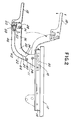
- a first support bracket or mounting plate 10 is mounted or attached to the underside of a desktop or work surface 12. More specifically, the first bracket or plate 10 includes a slide mechanism which enables sliding movement of the bracket or plate 10 in a channel 14 between the positions shown in Figure 2 in phantom and solid lines.
- the channel 14 is thus attached to the underside of a desktop 12, and the plate or bracket 10 slides in side tracks in the channel 14.
- the connection between the channel 14 and the plate 10 may be a pivotal connection so that the plate 10 will slide and pivot relative to the channel 14.
- the bracket 10 is connected with and supports a separate keyboard support platform 18 through a linkage which is comprised of a first arm 20 and a second arm 22.
- the arm 20 is attached by means of a pivot rod 24 to depending bracket plate 11 of bracket 10 and may pivot about the axis of rod 24. That is, parallel, spaced, depending bracket plates 11, 13 retain a pivot rod 24 suspended beneath sliding plate 10.
- the description focuses on one set of arms 20,22.
- the arms 20,22 may be constructed in tandem just as are the bracket plates 11,13.
- the arms 20,22 may also be a single member (as depicted) having a U channel shape.
- the first arm 20 is attached at its opposite end to the platform 18 by means of a pivot rod 26 which extends between and connects to projecting tabs or arms 28 of platform 18.
- the axes of rotation or pivotal axes associated with the pins 24 and 26 are generally parallel one to the other.
- a spiral spring 30 is wrapped around pin 24 and includes opposite ends which engage the plate 10 and arm 20 respectively causing the arm 20 to be biased to pivot about the pin 24 clockwise or upwardly toward the upper position of the assembly illustrated in Figure 2. It is noted that in Figure 2 the assembly is depicted in phantom and the phantom position is that which the assembly may move to upon actuation of the spring 30 against the arm 20.
- the arm 20 may be varied.
- the arm 20 has an arcuate connecting run 32 extending between a generally straight, first leg section 34 and a generally straight, second leg section 36.
- the arm 20 may thus curl outwardly from beneath a desk and upwardly above the horizontal plane of the desk. This enables the platform 18 to be elevated as depicted in Figure 2 to a position significantly above the work surface 12.
- a second arm 22 Also connecting between the bracket 10 and more particularly, the bracket plates 11, 13 toward the computer support platform and bracket 18 is a second arm 22.
- the second arm 22 is attached to the bracket 10 by means of a pivot rod 40 which is generally parallel to and spaced downwardly from the rod 24.
- the arm 22, likewise, includes an arcuate section or run 42 connecting a first, generally straight leg 44 to a second, generally straight leg 46 similar to the construction of the first arm 20, again to enable the platform 18 to be raised to an elevated position.
- the connection between the second arm 22 and the platform or bracket 18 is depicted in Figure 3 in greater detail and includes a pin 50 which projects through an arcuate slot 52 in the first arm 20 and engages into and passes through an opening 54 in the second arm.
- the arcuate slot 52 permits the pin 50 to move or slide therein as the arm 20 moves relative to the arm 22 during pivotal action of arm 20 about pins 24,26. Such sliding movement further serves to reorient the platform 18 (which is also connected to pin 50) and thereby keep the platform 18 horizontal.
- the pin 50 thus passes through a small slot opening 56 in an actuator or extension arm 58 extending from the platform 18.
- the pin 50 also extends through a wedge block or lock member 60.
- the wedge lock or block member 60 rides freely in an axial direction on the pin 50, slot opening 56 of actuator arm 58, opening 54 and slot 52. It is held in position by the head of the pin 50, namely head 62.
- the opposite end of the pin 50 may include a nut 63 or some other mechanism to preclude axial movement; for example, a connection tube which connects to the opposite side of the bracket platform 18.
- the axial extent or length of pin 50 between head 62 and a nut 63 is intermediate the maximum and minimum combined thickness or axial dimension of arms 20,22, actuator arm 58 and wedge block 60.
- the wedge block 60 includes an inclined surface 66 which engages with and slides against an inclined surface 68 associated with the actuator arm 58.
- the platform 18 is moved in the clockwise direction as depicted in Figure 2 or force is placed on the platform 18 so as to tend to move it in the clockwise direction.
- the arms 20 and 22 may then be moved or pivoted to a desired position.
- pressing down or moving the platform 18 in the counterclockwise direction will lock the arms 20,22 again in a fixed position. An opposite direction of force and movement releases the arms 20,22.
- the platform 18 may have a pivotal connection between the platform 18 and a keyboard plate.
- various wedge locking mechanisms or other locking mechanisms may be used to connect the arms 20,22 in response to slight pivotal movement of the actuator arm 18.
Landscapes
- Input From Keyboards Or The Like (AREA)
- Casings For Electric Apparatus (AREA)
Abstract
Description
Claims (7)
- A computer support arm assembly comprising, in combination:(a) an attachment member (10) for attachment to a work support;(b) a support member (18) for support of a keyboard or the like;(c) first and second arms (20,22) connected between the attachment and support members, said first arm (20) being pivotally connected to the attachment and support members respectively and pivotal about generally parallel axes (24,26), said second arm (22) being pivotally connected (40) to the attachment member at one end and slidably connected (50,52) to the first arm at the opposite end, said connection of the second arm to the first arm further including a releasable locking mechanism for precluding sliding movement thereof relative to one another at least partially by friction in response to a load force upon the support member.
- An assembly as claimed in claim 1, wherein the releasable locking mechanism is arranged to compress the arms (20,22) together, precluding sliding movement thereof.
- An assembly as claimed in claim 1 or 2, wherein the locking mechanism comprises at least one wedge member (60), said wedge member being operable to lock the arms (20,22) in a fixed position relative to each other.
- An assembly as claimed in claim 3, wherein the locking mechanism further comprises a pin (50) on which the wedge member (60) is mounted, such that when a force is applied to the support member, the wedge member slides on the pin so as to lock the arms (20,22) in a fixed position relative to each other.
- An assembly as claimed in claim 1 or 2, wherein the locking mechanism includes at least one wedge member (60) attached to the support member (18) or the second arm (22), said wedge member being slidably engageable to lock the arms in a fixed pivotal position.
- An assembly as claimed in claim 1 or 2, wherein the second arm (22) includes a pivot pin (50) at the end connected to the first arm (20), said first arm including an arcuate guide slot (52) for receipt of the pin, one of said pin or said support member further including a wedge member for engagement with the other to lock the arms when the support member (18) is rotated about the axis (26) connecting the support member and first arm.
- A computer support arm assembly comprising, in combination:(a) a first bracket member (10) for attachment to a work support;(b) a second bracket member (18) for support of a keyboard or the like;(c) a first linkage arm (20) pivotally connected to the first bracket member at one end and to the second bracket member at its opposite end;(d) a second linkage arm (22) pivotally connected to the first bracket member at one end and to the second bracket member at its opposite end, said second linkage member further connectable to the first linkage member along an elongated connection path (52) corresponding to the pivot connection of the second linkage member to the second bracket member; and(e) a locking mechanism for at least partially frictionally engaging the linkage members and second bracket member simultaneously to retain the second bracket member in a fixed orientation.
Applications Claiming Priority (2)
| Application Number | Priority Date | Filing Date | Title |
|---|---|---|---|
| US16013 | 1998-01-30 | ||
| US09/016,013 US6322031B1 (en) | 1998-01-30 | 1998-01-30 | Keyboard support tray with releasable wedge lock |
Publications (3)
| Publication Number | Publication Date |
|---|---|
| EP0933045A2 true EP0933045A2 (en) | 1999-08-04 |
| EP0933045A3 EP0933045A3 (en) | 2001-04-25 |
| EP0933045B1 EP0933045B1 (en) | 2005-11-02 |
Family
ID=21774891
Family Applications (1)
| Application Number | Title | Priority Date | Filing Date |
|---|---|---|---|
| EP99300698A Expired - Lifetime EP0933045B1 (en) | 1998-01-30 | 1999-01-29 | Keyboard support assembly |
Country Status (3)
| Country | Link |
|---|---|
| US (3) | US6322031B1 (en) |
| EP (1) | EP0933045B1 (en) |
| DE (1) | DE69928034D1 (en) |
Cited By (1)
| Publication number | Priority date | Publication date | Assignee | Title |
|---|---|---|---|---|
| US6450467B2 (en) * | 1998-10-14 | 2002-09-17 | Work-Rite Ergonomic Accessories, Inc. | Tilt adjustable keyboard support |
Families Citing this family (23)
| Publication number | Priority date | Publication date | Assignee | Title |
|---|---|---|---|---|
| US5924664A (en) | 1997-03-12 | 1999-07-20 | Ergo View Technologies Corp. | Keyboard support mechanism |
| US6322031B1 (en) * | 1998-01-30 | 2001-11-27 | Waterloo Furniture Components, Ltd. | Keyboard support tray with releasable wedge lock |
| US6877707B1 (en) * | 2000-05-02 | 2005-04-12 | Steelcase Development Corporation | Integrated keyboard platform and document support |
| US6478279B1 (en) * | 2000-06-12 | 2002-11-12 | Compx International Inc. | Adapter bracket for a keyboard platform support mechanism |
| US6398176B1 (en) * | 2001-02-12 | 2002-06-04 | Ching-Nan Liu | Supporting assembly for articles |
| EP1260630A1 (en) * | 2001-05-21 | 2002-11-27 | Axana 2000 s.r.l. | Improvement in a collapsible support frame, particularly for ironing-boards |
| CA2411180C (en) * | 2002-10-30 | 2007-07-31 | Knape & Vogt Manufacturing Company | Adjustable support assembly for a data entry/interface device for computers or the like |
| US7007907B2 (en) * | 2003-04-01 | 2006-03-07 | Chul Huh | Adjustable keyboard stand |
| US6929228B2 (en) * | 2003-06-25 | 2005-08-16 | Steelcase Development Corporation | Adjustable keyboard support |
| US7516923B2 (en) * | 2004-05-05 | 2009-04-14 | Jaco, Inc. | Pivoting keyboard and mouse tray |
| US7448585B2 (en) * | 2004-12-16 | 2008-11-11 | Sunway, Incorporated | Keyboard support assembly |
| US7188813B2 (en) * | 2005-06-06 | 2007-03-13 | Knape & Vogt Manufacturing Company | Adjustable support assembly |
| US7455270B2 (en) * | 2005-12-12 | 2008-11-25 | Weber Knapp Company | Support arm mechanism |
| US20070152122A1 (en) * | 2005-12-30 | 2007-07-05 | 3M Innovative Properties Company | Keyboard support assembly |
| US7725988B2 (en) * | 2006-02-15 | 2010-06-01 | Lg Electronics Inc. | Hinge assembly and mobile device having the same |
| US7533859B2 (en) * | 2006-11-03 | 2009-05-19 | Compx International Inc. | Articulating support arm with integral angled abutment |
| US8819879B1 (en) * | 2007-11-13 | 2014-09-02 | Encore Medical Asset Corporation | Therapeutic treatment table |
| US7710715B2 (en) * | 2008-02-25 | 2010-05-04 | International Business Machines Corporation | Assembly and method for enhancing structural integrity and improving serviceability of electronic card disposed in a computing environment |
| US7946551B1 (en) | 2008-03-24 | 2011-05-24 | Sava Cvek | Adjustable ergonomic keyboard, mouse, and wrist support |
| US20100224750A1 (en) * | 2009-03-04 | 2010-09-09 | Nimrod Webber | Loudspeaker tilting adapter |
| US8061668B1 (en) * | 2009-03-24 | 2011-11-22 | Sava Cvek | Adjustable ergonomic keyboard, mouse, and wrist support |
| US9320352B2 (en) | 2014-01-17 | 2016-04-26 | Knape & Vogt Manufacturing Company | Articulating support arm |
| US10154729B2 (en) | 2016-05-10 | 2018-12-18 | Knape & Vogt Manufacturing Company | Articulating ergonomic support arm |
Citations (8)
| Publication number | Priority date | Publication date | Assignee | Title |
|---|---|---|---|---|
| US4616798A (en) | 1982-06-07 | 1986-10-14 | Haworth, Inc. | Adjustable support for CRT keyboard |
| US4625657A (en) | 1984-05-15 | 1986-12-02 | Weber-Knapp Company | Adjustable keyboard supporting mechanism |
| US4632349A (en) | 1984-03-21 | 1986-12-30 | Anstey Pty. Ltd. | Support assembly |
| US4706919A (en) | 1986-12-17 | 1987-11-17 | Haworth, Inc. | Keyboard support with automatic lowering mechanism |
| US4776284A (en) | 1986-08-26 | 1988-10-11 | Kosuth Inc. | Retractable work station |
| US4826123A (en) | 1983-05-16 | 1989-05-02 | Knoll International, Inc. | Adjustable keyboard support |
| US4843978A (en) | 1987-07-27 | 1989-07-04 | Hon Industries, Inc. | Table with vertically adjustable work surface |
| US5037054A (en) | 1990-06-13 | 1991-08-06 | Waterloo Furniture Components Ltd. | Adjustable support mechanism for a keyboard platform |
Family Cites Families (5)
| Publication number | Priority date | Publication date | Assignee | Title |
|---|---|---|---|---|
| US4691888A (en) * | 1984-08-06 | 1987-09-08 | Cotterill Michael J | Keyboard support |
| US5292097A (en) | 1989-10-31 | 1994-03-08 | Russell Edwin R | Work surface support |
| US5294087A (en) * | 1991-10-18 | 1994-03-15 | Engineered Data Products, Inc. | Adjustable keyboard holder for computer workstation |
| US5791263A (en) * | 1993-07-23 | 1998-08-11 | Weber Knapp Company | Adjustable work surface |
| US6322031B1 (en) * | 1998-01-30 | 2001-11-27 | Waterloo Furniture Components, Ltd. | Keyboard support tray with releasable wedge lock |
-
1998
- 1998-01-30 US US09/016,013 patent/US6322031B1/en not_active Expired - Lifetime
-
1999
- 1999-01-29 DE DE69928034T patent/DE69928034D1/en not_active Expired - Lifetime
- 1999-01-29 EP EP99300698A patent/EP0933045B1/en not_active Expired - Lifetime
-
2001
- 2001-11-27 US US09/994,984 patent/US6523797B2/en not_active Expired - Lifetime
-
2002
- 2002-10-09 US US10/267,227 patent/US6601812B2/en not_active Expired - Lifetime
Patent Citations (8)
| Publication number | Priority date | Publication date | Assignee | Title |
|---|---|---|---|---|
| US4616798A (en) | 1982-06-07 | 1986-10-14 | Haworth, Inc. | Adjustable support for CRT keyboard |
| US4826123A (en) | 1983-05-16 | 1989-05-02 | Knoll International, Inc. | Adjustable keyboard support |
| US4632349A (en) | 1984-03-21 | 1986-12-30 | Anstey Pty. Ltd. | Support assembly |
| US4625657A (en) | 1984-05-15 | 1986-12-02 | Weber-Knapp Company | Adjustable keyboard supporting mechanism |
| US4776284A (en) | 1986-08-26 | 1988-10-11 | Kosuth Inc. | Retractable work station |
| US4706919A (en) | 1986-12-17 | 1987-11-17 | Haworth, Inc. | Keyboard support with automatic lowering mechanism |
| US4843978A (en) | 1987-07-27 | 1989-07-04 | Hon Industries, Inc. | Table with vertically adjustable work surface |
| US5037054A (en) | 1990-06-13 | 1991-08-06 | Waterloo Furniture Components Ltd. | Adjustable support mechanism for a keyboard platform |
Cited By (1)
| Publication number | Priority date | Publication date | Assignee | Title |
|---|---|---|---|---|
| US6450467B2 (en) * | 1998-10-14 | 2002-09-17 | Work-Rite Ergonomic Accessories, Inc. | Tilt adjustable keyboard support |
Also Published As
| Publication number | Publication date |
|---|---|
| DE69928034D1 (en) | 2005-12-08 |
| US6523797B2 (en) | 2003-02-25 |
| EP0933045B1 (en) | 2005-11-02 |
| US20030025055A1 (en) | 2003-02-06 |
| US6322031B1 (en) | 2001-11-27 |
| US6601812B2 (en) | 2003-08-05 |
| EP0933045A3 (en) | 2001-04-25 |
| US20020033435A1 (en) | 2002-03-21 |
Similar Documents
| Publication | Publication Date | Title |
|---|---|---|
| EP0933045B1 (en) | Keyboard support assembly | |
| US6076785A (en) | Ergonomic sit/stand keyboard support mechanism | |
| US5836560A (en) | Articulated keyboard shelf | |
| US6270047B1 (en) | Keyboard tilt mechanism | |
| JP4197758B2 (en) | Improved keyboard support mechanism | |
| EP0874569B1 (en) | Keyboard support assembly | |
| US6598844B2 (en) | Adjustable computer keyboard platform support mechanism | |
| US6942187B2 (en) | Adjustable tripod assembly | |
| US10154729B2 (en) | Articulating ergonomic support arm | |
| EP0610327A1 (en) | Adjustable keyboard holder for computer workstation | |
| US6442783B1 (en) | Dock leveler with run-off barrier configuration | |
| US6726168B2 (en) | Adjustable computer keyboard platform support mechanism | |
| US7448585B2 (en) | Keyboard support assembly | |
| AU564548B2 (en) | Seat tilting mechanism | |
| US7707946B2 (en) | Adjustable work surface support | |
| JPH09295797A (en) | Elevator for object | |
| JP2000152847A (en) | Attachment tablet | |
| JPH0622267Y2 (en) | Lifting shelf | |
| WO2023163977A1 (en) | Stowable step | |
| JPS5841948Y2 (en) | Floor plate support mechanism in a floor plate undulating bed | |
| JP2024035213A (en) | Desktop riser with locking assembly | |
| JPS63502489A (en) | customer business chair | |
| AU2001272208A1 (en) | Adjustable tripod assembly |
Legal Events
| Date | Code | Title | Description |
|---|---|---|---|
| PUAI | Public reference made under article 153(3) epc to a published international application that has entered the european phase |
Free format text: ORIGINAL CODE: 0009012 |
|
| AK | Designated contracting states |
Kind code of ref document: A2 Designated state(s): DE FR GB NL SE |
|
| AX | Request for extension of the european patent |
Free format text: AL;LT;LV;MK;RO;SI |
|
| PUAL | Search report despatched |
Free format text: ORIGINAL CODE: 0009013 |
|
| AK | Designated contracting states |
Kind code of ref document: A3 Designated state(s): AT BE CH CY DE DK ES FI FR GB GR IE IT LI LU MC NL PT SE |
|
| AX | Request for extension of the european patent |
Free format text: AL;LT;LV;MK;RO;SI |
|
| 17P | Request for examination filed |
Effective date: 20011024 |
|
| AKX | Designation fees paid |
Free format text: DE FR GB NL SE |
|
| 17Q | First examination report despatched |
Effective date: 20030620 |
|
| GRAP | Despatch of communication of intention to grant a patent |
Free format text: ORIGINAL CODE: EPIDOSNIGR1 |
|
| GRAS | Grant fee paid |
Free format text: ORIGINAL CODE: EPIDOSNIGR3 |
|
| GRAA | (expected) grant |
Free format text: ORIGINAL CODE: 0009210 |
|
| AK | Designated contracting states |
Kind code of ref document: B1 Designated state(s): DE FR GB NL SE |
|
| PG25 | Lapsed in a contracting state [announced via postgrant information from national office to epo] |
Ref country code: NL Free format text: LAPSE BECAUSE OF FAILURE TO SUBMIT A TRANSLATION OF THE DESCRIPTION OR TO PAY THE FEE WITHIN THE PRESCRIBED TIME-LIMIT Effective date: 20051102 |
|
| REG | Reference to a national code |
Ref country code: GB Ref legal event code: FG4D |
|
| REF | Corresponds to: |
Ref document number: 69928034 Country of ref document: DE Date of ref document: 20051208 Kind code of ref document: P |
|
| PG25 | Lapsed in a contracting state [announced via postgrant information from national office to epo] |
Ref country code: SE Free format text: LAPSE BECAUSE OF FAILURE TO SUBMIT A TRANSLATION OF THE DESCRIPTION OR TO PAY THE FEE WITHIN THE PRESCRIBED TIME-LIMIT Effective date: 20060202 Ref country code: GB Free format text: LAPSE BECAUSE OF NON-PAYMENT OF DUE FEES Effective date: 20060202 |
|
| PG25 | Lapsed in a contracting state [announced via postgrant information from national office to epo] |
Ref country code: DE Free format text: LAPSE BECAUSE OF FAILURE TO SUBMIT A TRANSLATION OF THE DESCRIPTION OR TO PAY THE FEE WITHIN THE PRESCRIBED TIME-LIMIT Effective date: 20060203 |
|
| NLV1 | Nl: lapsed or annulled due to failure to fulfill the requirements of art. 29p and 29m of the patents act | ||
| PLBE | No opposition filed within time limit |
Free format text: ORIGINAL CODE: 0009261 |
|
| STAA | Information on the status of an ep patent application or granted ep patent |
Free format text: STATUS: NO OPPOSITION FILED WITHIN TIME LIMIT |
|
| 26N | No opposition filed |
Effective date: 20060803 |
|
| GBPC | Gb: european patent ceased through non-payment of renewal fee |
Effective date: 20060202 |
|
| EN | Fr: translation not filed | ||
| PG25 | Lapsed in a contracting state [announced via postgrant information from national office to epo] |
Ref country code: FR Free format text: LAPSE BECAUSE OF FAILURE TO SUBMIT A TRANSLATION OF THE DESCRIPTION OR TO PAY THE FEE WITHIN THE PRESCRIBED TIME-LIMIT Effective date: 20061222 |
|
| PG25 | Lapsed in a contracting state [announced via postgrant information from national office to epo] |
Ref country code: FR Free format text: LAPSE BECAUSE OF FAILURE TO SUBMIT A TRANSLATION OF THE DESCRIPTION OR TO PAY THE FEE WITHIN THE PRESCRIBED TIME-LIMIT Effective date: 20060131 |
|
| PG25 | Lapsed in a contracting state [announced via postgrant information from national office to epo] |
Ref country code: FR Free format text: LAPSE BECAUSE OF FAILURE TO SUBMIT A TRANSLATION OF THE DESCRIPTION OR TO PAY THE FEE WITHIN THE PRESCRIBED TIME-LIMIT Effective date: 20051102 |