EP0932051A1 - Elektronisches Kommunikationssystem zwischen einer Basisstation und Transpondern - Google Patents
Elektronisches Kommunikationssystem zwischen einer Basisstation und Transpondern Download PDFInfo
- Publication number
- EP0932051A1 EP0932051A1 EP98101058A EP98101058A EP0932051A1 EP 0932051 A1 EP0932051 A1 EP 0932051A1 EP 98101058 A EP98101058 A EP 98101058A EP 98101058 A EP98101058 A EP 98101058A EP 0932051 A1 EP0932051 A1 EP 0932051A1
- Authority
- EP
- European Patent Office
- Prior art keywords
- communication
- transponder
- base station
- identification
- communication system
- Prior art date
- Legal status (The legal status is an assumption and is not a legal conclusion. Google has not performed a legal analysis and makes no representation as to the accuracy of the status listed.)
- Granted
Links
Images


Classifications
-
- G—PHYSICS
- G06—COMPUTING; CALCULATING OR COUNTING
- G06K—GRAPHICAL DATA READING; PRESENTATION OF DATA; RECORD CARRIERS; HANDLING RECORD CARRIERS
- G06K7/00—Methods or arrangements for sensing record carriers, e.g. for reading patterns
- G06K7/10—Methods or arrangements for sensing record carriers, e.g. for reading patterns by electromagnetic radiation, e.g. optical sensing; by corpuscular radiation
- G06K7/10009—Methods or arrangements for sensing record carriers, e.g. for reading patterns by electromagnetic radiation, e.g. optical sensing; by corpuscular radiation sensing by radiation using wavelengths larger than 0.1 mm, e.g. radio-waves or microwaves
- G06K7/10019—Methods or arrangements for sensing record carriers, e.g. for reading patterns by electromagnetic radiation, e.g. optical sensing; by corpuscular radiation sensing by radiation using wavelengths larger than 0.1 mm, e.g. radio-waves or microwaves resolving collision on the communication channels between simultaneously or concurrently interrogated record carriers.
- G06K7/10029—Methods or arrangements for sensing record carriers, e.g. for reading patterns by electromagnetic radiation, e.g. optical sensing; by corpuscular radiation sensing by radiation using wavelengths larger than 0.1 mm, e.g. radio-waves or microwaves resolving collision on the communication channels between simultaneously or concurrently interrogated record carriers. the collision being resolved in the time domain, e.g. using binary tree search or RFID responses allocated to a random time slot
- G06K7/10039—Methods or arrangements for sensing record carriers, e.g. for reading patterns by electromagnetic radiation, e.g. optical sensing; by corpuscular radiation sensing by radiation using wavelengths larger than 0.1 mm, e.g. radio-waves or microwaves resolving collision on the communication channels between simultaneously or concurrently interrogated record carriers. the collision being resolved in the time domain, e.g. using binary tree search or RFID responses allocated to a random time slot interrogator driven, i.e. synchronous
-
- G—PHYSICS
- G01—MEASURING; TESTING
- G01S—RADIO DIRECTION-FINDING; RADIO NAVIGATION; DETERMINING DISTANCE OR VELOCITY BY USE OF RADIO WAVES; LOCATING OR PRESENCE-DETECTING BY USE OF THE REFLECTION OR RERADIATION OF RADIO WAVES; ANALOGOUS ARRANGEMENTS USING OTHER WAVES
- G01S13/00—Systems using the reflection or reradiation of radio waves, e.g. radar systems; Analogous systems using reflection or reradiation of waves whose nature or wavelength is irrelevant or unspecified
- G01S13/74—Systems using reradiation of radio waves, e.g. secondary radar systems; Analogous systems
- G01S13/76—Systems using reradiation of radio waves, e.g. secondary radar systems; Analogous systems wherein pulse-type signals are transmitted
- G01S13/765—Systems using reradiation of radio waves, e.g. secondary radar systems; Analogous systems wherein pulse-type signals are transmitted with exchange of information between interrogator and responder
-
- G—PHYSICS
- G06—COMPUTING; CALCULATING OR COUNTING
- G06K—GRAPHICAL DATA READING; PRESENTATION OF DATA; RECORD CARRIERS; HANDLING RECORD CARRIERS
- G06K7/00—Methods or arrangements for sensing record carriers, e.g. for reading patterns
- G06K7/0008—General problems related to the reading of electronic memory record carriers, independent of its reading method, e.g. power transfer
-
- G—PHYSICS
- G01—MEASURING; TESTING
- G01S—RADIO DIRECTION-FINDING; RADIO NAVIGATION; DETERMINING DISTANCE OR VELOCITY BY USE OF RADIO WAVES; LOCATING OR PRESENCE-DETECTING BY USE OF THE REFLECTION OR RERADIATION OF RADIO WAVES; ANALOGOUS ARRANGEMENTS USING OTHER WAVES
- G01S13/00—Systems using the reflection or reradiation of radio waves, e.g. radar systems; Analogous systems using reflection or reradiation of waves whose nature or wavelength is irrelevant or unspecified
- G01S13/74—Systems using reradiation of radio waves, e.g. secondary radar systems; Analogous systems
- G01S13/75—Systems using reradiation of radio waves, e.g. secondary radar systems; Analogous systems using transponders powered from received waves, e.g. using passive transponders, or using passive reflectors
- G01S13/751—Systems using reradiation of radio waves, e.g. secondary radar systems; Analogous systems using transponders powered from received waves, e.g. using passive transponders, or using passive reflectors wherein the responder or reflector radiates a coded signal
- G01S13/758—Systems using reradiation of radio waves, e.g. secondary radar systems; Analogous systems using transponders powered from received waves, e.g. using passive transponders, or using passive reflectors wherein the responder or reflector radiates a coded signal using a signal generator powered by the interrogation signal
-
- G—PHYSICS
- G01—MEASURING; TESTING
- G01S—RADIO DIRECTION-FINDING; RADIO NAVIGATION; DETERMINING DISTANCE OR VELOCITY BY USE OF RADIO WAVES; LOCATING OR PRESENCE-DETECTING BY USE OF THE REFLECTION OR RERADIATION OF RADIO WAVES; ANALOGOUS ARRANGEMENTS USING OTHER WAVES
- G01S13/00—Systems using the reflection or reradiation of radio waves, e.g. radar systems; Analogous systems using reflection or reradiation of waves whose nature or wavelength is irrelevant or unspecified
- G01S13/74—Systems using reradiation of radio waves, e.g. secondary radar systems; Analogous systems
- G01S13/76—Systems using reradiation of radio waves, e.g. secondary radar systems; Analogous systems wherein pulse-type signals are transmitted
- G01S13/78—Systems using reradiation of radio waves, e.g. secondary radar systems; Analogous systems wherein pulse-type signals are transmitted discriminating between different kinds of targets, e.g. IFF-radar, i.e. identification of friend or foe
Definitions
- the present invention relates to a system for contactless electronic communication or RFID system.
- These systems typically used for identification people, animals or property (among others examples: vehicles, items requiring marking and sub-assemblies in a production line, etc.), mainly consist of an interrogator / reader and a or several transponders each associated with an article to be identified.
- the interrogator / reader emits a signal question mark in the form of radiation electromagnetic.
- Transponders subject to this field electromagnetic interrogation respond with the generation of a normally consistent response signal by modulating this field, and generally providing a code / address identifying the transponder.
- European patent EP 0 161 779 describes such a system identification where the interrogator / reader is arranged to re-issue the identification code transmitted by a transponder.
- Each transponder includes means for comparison of the reissued identification code with its own identification code, and is designed to be disconnect in case of correspondence.
- European patent application EP 0 585 132 describes a other identification system in which the protocol identification is significantly simplified.
- the interrogator / reader is arranged to transmit an identification message reception signal transmitted by one of the transponders in the form of a modification of the interrogation signal. This modification is performed synchronously with the signal response, each transponder being arranged to stop the transmission of the response signal upon detection of said modification of the interrogation signal.
- the identification system described in the request mentioned above offers a simple and reliable solution to problem of identifying and counting a plurality transponders.
- this system only offers action restricted to the transmission of an order inhibition of the identified transponder, and is thus limited to identification and counting applications a plurality of transponders.
- An object of the present invention is to provide a communication system which, in addition to the function identification of a plurality of transponders, allows to the interrogator / reader (hereinafter referred to as base station) selectively control the transponders and / or selectively exchange information with these transponders.
- the subject of the invention is therefore a system of contactless electronic communication, including base station and a plurality of transponders, said base station comprising transmission means for emit an electromagnetic field defining a volume in which are likely to find multiple transponders, each transponder comprising means for receiving said field electromagnetic and means for generating, in response said electromagnetic field, an identification message likely to be read by the base station, this base station further comprising means for receipt of said identification message from a any transponder among said plurality of transponders, and processing means allowing the verification of the validity of said message of identification, this communication system being characterized in that the base station includes means for generating opening signals of communications intended for said plurality of transponders, said base station providing a communication opening signal to each transponder from which it receives an identification message, each transponder being arranged to open a window of communication in response to said opening signal from communication only when it is received during a predefined period relative to the generation of said identification message.
- An advantage of the present invention is to be able selectively communicate with each transponder interrogates.
- Each transponder being identified individually by the base station, only said identified transponder enters into communication with the base station.
- Another advantage of the present invention is to allow several modes of communication between the base station and transponders for example a mode where at least one order is provided to the transponder to be executed later, or a mode where the base station reads at least one information stored in the transponder's memory.
- a mixed mode combining command (s) and reading (s) can easily be provided in the context of the invention.
- Another advantage of the present invention is to ability to adapt communication between base station and the transponders selectively based on the identification issued by them. It is indeed possible by the present invention to generate a specific communication for each transponder identified in an advanced system.
- the transponders used in the communication system are preferably of the passive type. However, this does not constitute not a limitation, active type transponders can also be used.
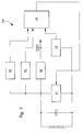
- Figure 1 shows a block diagram of such a transponder identified by the reference general TR. This includes a resonant circuit formed typically of an inductance and a capacity (not referenced) connected in parallel, and a circuit electronic can easily be done on the same integrated component.
- a modulator 11 allows the encoding of information to be transmitted to the base station by load switching of the resonant circuit. The coupling electromagnetic thus produced is detected by the station basic. The power supply to the electronic circuit is extracted from the ambient electromagnetic field through of the resonant circuit and then rectified by a rectifier 12.
- An initialization circuit 13 makes it possible to initialize a logic unit 14 when the power is on sufficient to guarantee proper operational functioning of the transponder.
- a clock signal is extracted from the frequency of the ambient electromagnetic field through clock extraction means 15. All transponders thus operate synchronously with the base station.
- a monostable rocker 16 further allows the detection of electromagnetic field interruptions.
- Her time constant has a value corresponding to several electromagnetic field periods.
- Logic unit 14 of the transponder further comprises means for storage (ROM and EEPROM or other types of memory) containing a transponder code / address and any other information recorded during manufacture or later.
- FIG. 2 shows schematically the working principle of the communication system according to the present invention.
- Base station 20 performs operations in a sequence that can broadly be broken down into three phases, one phase interrogation (A), an identification phase and communication opening (B) and a phase of communication (C), this distinction being defined here only to explain how the communication system described in this invention.
- the transponders 21 to 26 are identified by the abbreviation TR.
- the interrogation phase (A) is characterized by the transmission by the base station 20 of a field electromagnetic 1 at a specific frequency.
- This field electromagnetic 1 defines a communication volume 2 in which one or more transponders 21, 22 and 23 among the plurality of transponders 21 to 26 are likely to be found.
- Transponders 21, 22 and 23 being included in communication volume 2 are activated and interpret the presence of the field 1 as an interrogation signal.
- Each transponder 21, 22 and 23 thus subjected to the field electromagnetic 1 answers this question with the generation of an identification message 30 specific to each of them.
- the identification and opening phase of communication (B) begins upon receipt by the base station 20 of an identification message 30 emanating from any transponder among the transponders 21, 22 and 23 subject to the field electromagnetic 1, in the example the transponder 22.
- the station basic 20 Upon receipt of the identification message 30, the station basic 20 then checks the message identification 30.
- the base station 20 generates a short signal 40, referred to herein invention as a communication opening signal, as a change in the field electromagnetic 1 indicating to the selected transponder 22 that his identification message 30 is being processing and that it must, at the end of the transmission thereof, open a communication window 60.
- This signal communication opening 40 is generated during a predefined period relative to the generation of said identification message 30, i.e. either during or at the end of the transmission of the identification message 30.
- the transponders 21 to 26 are therefore arranged to receive the communication open signal 40 only during this predefined period.
- the communication phase (C) as such begins after the verification of the identification message 30 transmitted by the transponder identified 22. Upon opening the window communication 60, base station 20 and transponder identified 22 have the opportunity to enter into communication and exchange information.
- the message identification 30 is preferably repeated after long pauses of random duration during which the TR transponder remains inactive, allowing the base station 20 to receive an identification message 30 from another transponder while avoiding that, in the worst case, two or more messages 30 are perpetually colliding.
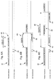
- Figure 3 schematically shows a example of transmission of an identification message 30 in the case where two transponders are subjected to the field electromagnetic 1. It is important to note that the duration of breaks is significantly longer than the duration transmission of the identification message 30. As a result, the breaks shown in Figure 3 have been reduced to facilitate the illustration of the collision problem.
- Manchester type coding is used as an example only in the rest of the description.
- Figure 4 shows such an example of coding Manchester type. This type of coding is characterized by a negative or positive transition in the middle of the one bit period. "1" is represented by the sequence ON-OFF and "0" is represented by the sequence OFF-ON. The period of a bit is set to a multiple of the field period electromagnetic 1.
- FIG. 5 shows an example of the structure of a identification message 30 as defined in the present invention.
- This identification message 30 is consists of a first initialization sequence 31 used to synchronize base station 20 on the coded message 32 directly following this sequence initialization 31, the coded message 32 containing a code transponder identification.
- the initialization sequence 31, here seven bits to 0 followed by a bit at 1, is followed by a coded message 32 with a length of 5 bits.
- the communication opening signal 40 transmitted by base station 20 is obtained by one or more momentary interruptions of the electromagnetic field 1 during a predefined period relative to the generation of the identification message 30, these interruptions having shorter than the period of a bit.
- the opening signal of communication 40 consists of two interruptions momentary 51 and 52 of the electromagnetic field 1 during bits 1 and 5 of the coded message following the sequence initialization.
- An interruption can be made at any time during the one-bit period but preferably during the period when the modulator 11 (figure 1) is ON. Indeed, during this period, the resonant circuit is discharged so that the oscillation clean of the transponder is amortized more quickly than during the period the switch is OFF.
- the monostable scale 16 in conjunction with the logic 14 are here adapted to detect the electromagnetic field interruptions during bits 1 and 5 of the coded message. It is important to note that the example in figure 5 is only a variant possible structure of an identification message 30 and a communication opening signal 40.
- FIGS. 6A to 6C are shown different embodiments of the present invention. Others embodiments can be envisioned by those skilled in the art job.
- FIG. 6A represents a first mode of embodiment of the invention in which the transponder identified 22 simply transmits information 32 to the base station 20 during the communication window 60.
- the opening signal of communication 40 is by default interpreted by the transponder identified 22 as an information request, the latter thus opening a communication window 60 to transmit the required information 32.
- This mode of achievement can typically be applied to the management of goods where you only want information precise stored in the memory of the identified transponder 22, for example the price of an item or the deadline for sale of a product intended for consumption.
- FIG. 6B describes another embodiment of the invention in which the base station 20 transmits a command 44 which must subsequently be executed by the transponder identified 22.
- the transponder identified 22 thus opens a communication window 60 for receive a command 44 from the base station 20.
- This command 44 is interpreted and thereafter executed by the identified transponder 22.
- This mode of realization is typically applicable to systems anti-theft or access control.
- FIG. 6C describes another embodiment of the invention in which the base station 20 transmits, first, an information request 42 stored in the memory of the identified transponder 22 then, secondly, a command 44 that the identified transponder 22 must subsequently execute.
- the transponder identified 22 thus opens a window of communication 60 allowing it to successively receive information request 42, to transmit the information 32 required and finally receive the command 44.
- This embodiment offers the possibility of adapting the command 44 according to the information 32 transmitted by the identified transponder.
- FIG 7 illustrates the situation where no signal containing a request, an order or any other information is not received by the identified transponder 22 in the embodiments shown in Figures 6B and 6C.
- Each TR transponder is in fact designed to detect if a signal is transmitted by the base station 20 during a predefined period of time at the start of the communication window 60. If no signal containing the information is not detected, the transponder identified 22 close communication window 60 and continue to transmit its identification message 30 after a break.
- the duration of the communication window 60 can be variable, the end of said window communication 60 which can be associated with the end of the transmission of information 32 as described in the embodiment of FIG. 6A, to a command 44 such as described in the embodiments of FIGS. 6B and 6C, or the absence of exchange of information during the predefined duration period at the start of the window communication 60 (figure 7).
Landscapes
- Engineering & Computer Science (AREA)
- Physics & Mathematics (AREA)
- Remote Sensing (AREA)
- General Physics & Mathematics (AREA)
- Radar, Positioning & Navigation (AREA)
- Computer Networks & Wireless Communication (AREA)
- Artificial Intelligence (AREA)
- Computer Vision & Pattern Recognition (AREA)
- Theoretical Computer Science (AREA)
- Health & Medical Sciences (AREA)
- Toxicology (AREA)
- General Health & Medical Sciences (AREA)
- Electromagnetism (AREA)
- Radar Systems Or Details Thereof (AREA)
- Mobile Radio Communication Systems (AREA)
- Burglar Alarm Systems (AREA)
- Communication Control (AREA)
Priority Applications (5)
| Application Number | Priority Date | Filing Date | Title |
|---|---|---|---|
| AT98101058T ATE395618T1 (de) | 1998-01-22 | 1998-01-22 | Elektronisches kommunikationssystem zwischen einen basis-station und transpondern |
| DE69839476T DE69839476D1 (de) | 1998-01-22 | 1998-01-22 | Elektronisches Kommunikationssystem zwischen einen Basis-Station und Transpondern |
| EP98101058A EP0932051B1 (de) | 1998-01-22 | 1998-01-22 | Elektronisches Kommunikationssystem zwischen einen Basis-Station und Transpondern |
| JP11013252A JP2000101472A (ja) | 1998-01-22 | 1999-01-21 | 通信システム |
| US09/236,228 US6150934A (en) | 1998-01-22 | 1999-01-22 | Electronic communication system between a base station and transponders |
Applications Claiming Priority (1)
| Application Number | Priority Date | Filing Date | Title |
|---|---|---|---|
| EP98101058A EP0932051B1 (de) | 1998-01-22 | 1998-01-22 | Elektronisches Kommunikationssystem zwischen einen Basis-Station und Transpondern |
Publications (2)
| Publication Number | Publication Date |
|---|---|
| EP0932051A1 true EP0932051A1 (de) | 1999-07-28 |
| EP0932051B1 EP0932051B1 (de) | 2008-05-14 |
Family
ID=8231294
Family Applications (1)
| Application Number | Title | Priority Date | Filing Date |
|---|---|---|---|
| EP98101058A Expired - Lifetime EP0932051B1 (de) | 1998-01-22 | 1998-01-22 | Elektronisches Kommunikationssystem zwischen einen Basis-Station und Transpondern |
Country Status (5)
| Country | Link |
|---|---|
| US (1) | US6150934A (de) |
| EP (1) | EP0932051B1 (de) |
| JP (1) | JP2000101472A (de) |
| AT (1) | ATE395618T1 (de) |
| DE (1) | DE69839476D1 (de) |
Cited By (1)
| Publication number | Priority date | Publication date | Assignee | Title |
|---|---|---|---|---|
| FR3057975A1 (fr) * | 2016-10-24 | 2018-04-27 | Uqode | Systeme d'automatisation d'inventaire utilisant des etiquettes radiofrequence. |
Families Citing this family (11)
| Publication number | Priority date | Publication date | Assignee | Title |
|---|---|---|---|---|
| US6951305B2 (en) * | 2001-11-21 | 2005-10-04 | Goliath Solutions, Llc. | Advertising compliance monitoring system |
| US7374096B2 (en) | 2001-11-21 | 2008-05-20 | Goliath Solutions, Llc | Advertising compliance monitoring system |
| US6837427B2 (en) * | 2001-11-21 | 2005-01-04 | Goliath Solutions, Llc. | Advertising compliance monitoring system |
| US7009526B2 (en) * | 2002-10-02 | 2006-03-07 | Battelle Memorial Institute | RFID system and method including tag ID compression |
| US7023817B2 (en) * | 2003-03-11 | 2006-04-04 | Motorola, Inc. | Method and apparatus for source device synchronization in a communication system |
| US7240833B2 (en) * | 2004-05-20 | 2007-07-10 | Cardiac Pacemakers, Inc. | System and method of managing information for an implantable medical device |
| US7889058B2 (en) * | 2004-07-29 | 2011-02-15 | Mitsubishi Electric Corporation | Radio-tag reading system, radio-tag reader, and radio tag |
| US7417545B1 (en) * | 2005-11-03 | 2008-08-26 | Ncr Corporation | Method of determining failure of a communication base station |
| US7310070B1 (en) | 2006-08-23 | 2007-12-18 | Goliath Solutions, Llc | Radio frequency identification shelf antenna with a distributed pattern for localized tag detection |
| KR101037432B1 (ko) | 2009-03-05 | 2011-05-30 | 전자부품연구원 | 자기장 통신 네트워크를 위한 무선 통신 방법 및 코디네이터의 복조 장치 |
| WO2015198753A1 (ja) * | 2014-06-26 | 2015-12-30 | 古野電気株式会社 | 信号処理装置、トランスポンダ装置、レーダ装置、および、信号処理方法 |
Citations (3)
| Publication number | Priority date | Publication date | Assignee | Title |
|---|---|---|---|---|
| EP0427342A1 (de) * | 1989-11-10 | 1991-05-15 | Koninklijke Philips Electronics N.V. | Datenübertragungssystem |
| US5365551A (en) * | 1992-12-15 | 1994-11-15 | Micron Technology, Inc. | Data communication transceiver using identification protocol |
| EP0779520A2 (de) * | 1995-12-12 | 1997-06-18 | AT&T Corp. | Verbessertes moduliertes Rückstrahlungssystem für eine Aufwärtsverbindung |
Family Cites Families (3)
| Publication number | Priority date | Publication date | Assignee | Title |
|---|---|---|---|---|
| GB8408538D0 (en) * | 1984-04-03 | 1984-05-16 | Senelco Ltd | Transmitter-responder systems |
| US5557280A (en) * | 1992-08-26 | 1996-09-17 | British Technology Group Limited | Synchronized electronic identification system |
| FR2738370B1 (fr) * | 1995-09-06 | 1997-11-07 | France Telecom | Installation pour l'echange d'informations a distance entre un objet portatif passif et une station, objet et station correspondants |
-
1998
- 1998-01-22 DE DE69839476T patent/DE69839476D1/de not_active Expired - Lifetime
- 1998-01-22 EP EP98101058A patent/EP0932051B1/de not_active Expired - Lifetime
- 1998-01-22 AT AT98101058T patent/ATE395618T1/de not_active IP Right Cessation
-
1999
- 1999-01-21 JP JP11013252A patent/JP2000101472A/ja active Pending
- 1999-01-22 US US09/236,228 patent/US6150934A/en not_active Expired - Lifetime
Patent Citations (3)
| Publication number | Priority date | Publication date | Assignee | Title |
|---|---|---|---|---|
| EP0427342A1 (de) * | 1989-11-10 | 1991-05-15 | Koninklijke Philips Electronics N.V. | Datenübertragungssystem |
| US5365551A (en) * | 1992-12-15 | 1994-11-15 | Micron Technology, Inc. | Data communication transceiver using identification protocol |
| EP0779520A2 (de) * | 1995-12-12 | 1997-06-18 | AT&T Corp. | Verbessertes moduliertes Rückstrahlungssystem für eine Aufwärtsverbindung |
Cited By (1)
| Publication number | Priority date | Publication date | Assignee | Title |
|---|---|---|---|---|
| FR3057975A1 (fr) * | 2016-10-24 | 2018-04-27 | Uqode | Systeme d'automatisation d'inventaire utilisant des etiquettes radiofrequence. |
Also Published As
| Publication number | Publication date |
|---|---|
| US6150934A (en) | 2000-11-21 |
| ATE395618T1 (de) | 2008-05-15 |
| JP2000101472A (ja) | 2000-04-07 |
| EP0932051B1 (de) | 2008-05-14 |
| DE69839476D1 (de) | 2008-06-26 |
Similar Documents
| Publication | Publication Date | Title |
|---|---|---|
| EP0932051B1 (de) | Elektronisches Kommunikationssystem zwischen einen Basis-Station und Transpondern | |
| US5606313A (en) | Low power addressable data communication device and method | |
| EP0447278A2 (de) | Anlage zur Fernsteuerung von Preisanzeigen in einem Geschäft | |
| EP1438695A1 (de) | Kontaktfreie integrierte schaltung mit automatischen rahmenidentifikationsmitteln | |
| FR2689997A1 (fr) | Système d'échange de données sans contact entre un terminal et un ensemble portatif modulaire. | |
| EP2652670B1 (de) | Verfahren zur verwaltung des dialogs zwischen einem geräteteil und mindestens einem mehrzweckobjekt wie einer kontaktlosen chipkarte sowie entsprechendes objekt | |
| EP1372120A1 (de) | Authentifizierung eines elektronischen Etiketts | |
| EP1445877B1 (de) | Kommunikation zwischen elektromagnetischen Transpondern | |
| FR2871312A1 (fr) | Modulation de charge dans un transpondeur electromagnetique | |
| EP1407426A1 (de) | Verfahren zum schlüssellosen entriegeln einer zugangstür zu einem abgeschlossenen bereich | |
| EP0957442B1 (de) | Elektronisches Identifizierungssystem für mehrere Transponder | |
| EP1559066B1 (de) | Integrierte rfid-uhf-schaltung | |
| EP0954824B1 (de) | Kommunikationssystem mittels fernabfrage zur übertragung von abschaltbefehlen | |
| EP1163625B1 (de) | Festhalten eines kanals mit antikollision in einem elektronischen identifizierungssystem | |
| EP1066585B1 (de) | Verfahren zum simultanen schreiben einer gemeinschaftlichen nachricht in kontaktlosen etiketten | |
| WO1999060510A1 (fr) | Systeme d'identification electronique d'une pluralite de transpondeurs | |
| FR2776407A1 (fr) | Systeme et procede pour realiser des fonctions particulieres dans des etiquettes sans contact | |
| EP1220163A1 (de) | System zum Erfassen des Passierens von Personen oder Gegenständen durch einen räumlich begrenzten Ein- und Ausgang | |
| EP1538557A2 (de) | Widerstands- und Kapazitätsmodulation in einem elektromagnetischen Transponder | |
| EP0942387B1 (de) | Verfahren und System zum mehrmals Lesen einer dynamischen Sammlung von Etiketten | |
| CA2297797A1 (fr) | Objet portatif a communication sans contact suivant deux voies de communication, inductive et hertzienne | |
| FR2800186A1 (fr) | Systeme de gestion de produits portant des etiquettes electroniques sans contact | |
| EP1302889B1 (de) | Transponder und entsprechendes Steuerungsverfahren zur Verringerung der ausgesendeten Störsignale | |
| EP1230630B1 (de) | Vorrichtung zum erkennen und identifizieren der bewegung eines gegenstandes | |
| EP0750269A1 (de) | System zur Identifizierung von Gegenständen |
Legal Events
| Date | Code | Title | Description |
|---|---|---|---|
| PUAI | Public reference made under article 153(3) epc to a published international application that has entered the european phase |
Free format text: ORIGINAL CODE: 0009012 |
|
| AK | Designated contracting states |
Kind code of ref document: A1 Designated state(s): AT CH DE FR GB LI NL |
|
| RTI1 | Title (correction) |
Free format text: ELECTRONIC COMMUNICATION SYSTEM BETWEEN A BASE STATION AND TRANSPONDERS |
|
| 17P | Request for examination filed |
Effective date: 20000128 |
|
| AKX | Designation fees paid |
Free format text: AT CH DE FR GB LI NL |
|
| GRAP | Despatch of communication of intention to grant a patent |
Free format text: ORIGINAL CODE: EPIDOSNIGR1 |
|
| GRAS | Grant fee paid |
Free format text: ORIGINAL CODE: EPIDOSNIGR3 |
|
| GRAA | (expected) grant |
Free format text: ORIGINAL CODE: 0009210 |
|
| AK | Designated contracting states |
Kind code of ref document: B1 Designated state(s): AT CH DE FR GB LI NL |
|
| REG | Reference to a national code |
Ref country code: GB Ref legal event code: FG4D Free format text: NOT ENGLISH |
|
| REG | Reference to a national code |
Ref country code: CH Ref legal event code: EP |
|
| REF | Corresponds to: |
Ref document number: 69839476 Country of ref document: DE Date of ref document: 20080626 Kind code of ref document: P |
|
| PG25 | Lapsed in a contracting state [announced via postgrant information from national office to epo] |
Ref country code: AT Free format text: LAPSE BECAUSE OF FAILURE TO SUBMIT A TRANSLATION OF THE DESCRIPTION OR TO PAY THE FEE WITHIN THE PRESCRIBED TIME-LIMIT Effective date: 20080514 |
|
| PLBE | No opposition filed within time limit |
Free format text: ORIGINAL CODE: 0009261 |
|
| STAA | Information on the status of an ep patent application or granted ep patent |
Free format text: STATUS: NO OPPOSITION FILED WITHIN TIME LIMIT |
|
| 26N | No opposition filed |
Effective date: 20090217 |
|
| GBPC | Gb: european patent ceased through non-payment of renewal fee |
Effective date: 20090122 |
|
| PG25 | Lapsed in a contracting state [announced via postgrant information from national office to epo] |
Ref country code: GB Free format text: LAPSE BECAUSE OF NON-PAYMENT OF DUE FEES Effective date: 20090122 |
|
| REG | Reference to a national code |
Ref country code: FR Ref legal event code: PLFP Year of fee payment: 19 |
|
| REG | Reference to a national code |
Ref country code: FR Ref legal event code: PLFP Year of fee payment: 20 |
|
| PGFP | Annual fee paid to national office [announced via postgrant information from national office to epo] |
Ref country code: NL Payment date: 20161220 Year of fee payment: 20 Ref country code: CH Payment date: 20161223 Year of fee payment: 20 |
|
| PGFP | Annual fee paid to national office [announced via postgrant information from national office to epo] |
Ref country code: FR Payment date: 20161221 Year of fee payment: 20 |
|
| PGFP | Annual fee paid to national office [announced via postgrant information from national office to epo] |
Ref country code: DE Payment date: 20161219 Year of fee payment: 20 |
|
| REG | Reference to a national code |
Ref country code: DE Ref legal event code: R071 Ref document number: 69839476 Country of ref document: DE |
|
| REG | Reference to a national code |
Ref country code: NL Ref legal event code: MK Effective date: 20180121 |
|
| REG | Reference to a national code |
Ref country code: CH Ref legal event code: PL |