EP0931920A2 - Portable generator - Google Patents
Portable generator Download PDFInfo
- Publication number
- EP0931920A2 EP0931920A2 EP99100828A EP99100828A EP0931920A2 EP 0931920 A2 EP0931920 A2 EP 0931920A2 EP 99100828 A EP99100828 A EP 99100828A EP 99100828 A EP99100828 A EP 99100828A EP 0931920 A2 EP0931920 A2 EP 0931920A2
- Authority
- EP
- European Patent Office
- Prior art keywords
- shroud
- case
- engine
- generator
- sound insulating
- Prior art date
- Legal status (The legal status is an assumption and is not a legal conclusion. Google has not performed a legal analysis and makes no representation as to the accuracy of the status listed.)
- Granted
Links
Images


Classifications
-
- F—MECHANICAL ENGINEERING; LIGHTING; HEATING; WEAPONS; BLASTING
- F02—COMBUSTION ENGINES; HOT-GAS OR COMBUSTION-PRODUCT ENGINE PLANTS
- F02B—INTERNAL-COMBUSTION PISTON ENGINES; COMBUSTION ENGINES IN GENERAL
- F02B75/00—Other engines
- F02B75/16—Engines characterised by number of cylinders, e.g. single-cylinder engines
-
- F—MECHANICAL ENGINEERING; LIGHTING; HEATING; WEAPONS; BLASTING
- F02—COMBUSTION ENGINES; HOT-GAS OR COMBUSTION-PRODUCT ENGINE PLANTS
- F02B—INTERNAL-COMBUSTION PISTON ENGINES; COMBUSTION ENGINES IN GENERAL
- F02B63/00—Adaptations of engines for driving pumps, hand-held tools or electric generators; Portable combinations of engines with engine-driven devices
- F02B63/04—Adaptations of engines for driving pumps, hand-held tools or electric generators; Portable combinations of engines with engine-driven devices for electric generators
- F02B63/044—Adaptations of engines for driving pumps, hand-held tools or electric generators; Portable combinations of engines with engine-driven devices for electric generators the engine-generator unit being placed on a frame or in an housing
- F02B2063/045—Frames for generator-engine sets
-
- F—MECHANICAL ENGINEERING; LIGHTING; HEATING; WEAPONS; BLASTING
- F02—COMBUSTION ENGINES; HOT-GAS OR COMBUSTION-PRODUCT ENGINE PLANTS
- F02B—INTERNAL-COMBUSTION PISTON ENGINES; COMBUSTION ENGINES IN GENERAL
- F02B63/00—Adaptations of engines for driving pumps, hand-held tools or electric generators; Portable combinations of engines with engine-driven devices
- F02B63/04—Adaptations of engines for driving pumps, hand-held tools or electric generators; Portable combinations of engines with engine-driven devices for electric generators
- F02B63/044—Adaptations of engines for driving pumps, hand-held tools or electric generators; Portable combinations of engines with engine-driven devices for electric generators the engine-generator unit being placed on a frame or in an housing
- F02B2063/046—Handles adapted therefor, e.g. handles or grips for movable units
-
- F—MECHANICAL ENGINEERING; LIGHTING; HEATING; WEAPONS; BLASTING
- F02—COMBUSTION ENGINES; HOT-GAS OR COMBUSTION-PRODUCT ENGINE PLANTS
- F02B—INTERNAL-COMBUSTION PISTON ENGINES; COMBUSTION ENGINES IN GENERAL
- F02B75/00—Other engines
- F02B75/02—Engines characterised by their cycles, e.g. six-stroke
- F02B2075/022—Engines characterised by their cycles, e.g. six-stroke having less than six strokes per cycle
- F02B2075/027—Engines characterised by their cycles, e.g. six-stroke having less than six strokes per cycle four
-
- F—MECHANICAL ENGINEERING; LIGHTING; HEATING; WEAPONS; BLASTING
- F02—COMBUSTION ENGINES; HOT-GAS OR COMBUSTION-PRODUCT ENGINE PLANTS
- F02B—INTERNAL-COMBUSTION PISTON ENGINES; COMBUSTION ENGINES IN GENERAL
- F02B63/00—Adaptations of engines for driving pumps, hand-held tools or electric generators; Portable combinations of engines with engine-driven devices
- F02B63/04—Adaptations of engines for driving pumps, hand-held tools or electric generators; Portable combinations of engines with engine-driven devices for electric generators
- F02B63/044—Adaptations of engines for driving pumps, hand-held tools or electric generators; Portable combinations of engines with engine-driven devices for electric generators the engine-generator unit being placed on a frame or in an housing
- F02B63/048—Portable engine-generator combinations
-
- F—MECHANICAL ENGINEERING; LIGHTING; HEATING; WEAPONS; BLASTING
- F05—INDEXING SCHEMES RELATING TO ENGINES OR PUMPS IN VARIOUS SUBCLASSES OF CLASSES F01-F04
- F05C—INDEXING SCHEME RELATING TO MATERIALS, MATERIAL PROPERTIES OR MATERIAL CHARACTERISTICS FOR MACHINES, ENGINES OR PUMPS OTHER THAN NON-POSITIVE-DISPLACEMENT MACHINES OR ENGINES
- F05C2201/00—Metals
- F05C2201/02—Light metals
- F05C2201/021—Aluminium
Definitions
- the present invention relates to an engine and a portable generator having an engine and a generator body driven by the engine and accommodated within a sound insulating case together with the engine.
- a known portable generator includes an engine and a generator body driven by the engine, both being accommodated within a sound insulating case with a carrying handle provided at an upper part thereof for allowing gripping so that the generator can be hand-carried from one place to another.
- the sound insulating case needs to have increased rigidity, because it must support the heavy engine and generator body accommodated therein when the generator is lifted up for transportation by an operator's hand holding the carrying handle.
- the proposed generator comprises a frame unit consisting of a pair of right and left frame members connected in spaced relation to each other via a lower-positioned bottom cover and an upper-positioned carrying handle, an accommodating case comprised of plural soundproof covers arranged to surround the frame unit, and an engine and a generator body accommodated within the accommodating case.
- a portable generator which comprises an engine, a generator body driven by the engine, a sound insulating case accommodating the engine and the generator body and having a carrying handle, and a cooling and ventilating shroud surrounding at least a crankcase and a cylinder block of the engine, the shroud comprising a split shroud composed of a pair of right and left shroud halves, the engine being fixed to the split shroud, the split shroud having an upper joined portion and a lower joined portion, at least the upper joined portion being accommodated in and connected to the sound insulating case.
- the engine is fixed to the shroud having its upper part connected to the carrying handle formed integrally with an upper part of the case. Therefore, the load of the engine is applied to the carrying handle of the case through the shroud when the portable generator is lifted up with a hand.
- it is not necessary to increase rigidity of the case.
- the shroud serves as a support member for supporting the engine at the upper part of the sound insulating case.
- the portable generator since at least a crankcase and a cylinder of the engine are surrounded by the shroud and further accommodated within the case, the portable generator has a double sound insulating structure. Furthermore, since the shroud is composed of a pair of right and left split halves, the engine can be surrounded readily.
- each of the upper and lower joined portions of the split shroud is accommodated in and connected to the sound insulating case via a vibration-proof member.
- a vibration-proof member is advantageous in that vibration generated upon operation of the engine is attenuated by the vibration-proof member provided at the upper and lower joined portions of the shroud and hence the least vibration is transmitted to the sound insulating case.
- the split shroud is formed of a steel plate while the sound insulating case is formed of a synthetic resin. This is advantageous in that the split shroud is imparted with rigidity sufficient for supporting the engine and generator body. Further, it becomes possible to reduce the weight of the case and the cost of production of the same.
- the sound insulating case includes a lower part having rigidity larger than that of the other part thereof. This makes it unnecessary to improve the rigidity of the entire case, whereby lightening of the case itself is enabled.
- the generator body may be disposed at an entrance side of the shroud.
- a muffler for the engine may be disposed at an exit side of the shroud.
- the generator body may comprise a magneto generator having an outer rotor driven by the engine.
- the generator body may include a cooling fan mounted to the outer rotor for taking external air through an intake port of the case into the shroud and discharging the air from the case after cooling an outer periphery of the engine and then the muffler.
- profiled arrows Fr, Rr, L and R are used to indicated respectively the forward, rearward, leftward and rightward directions of a portable generator 1 embodying the present invention.
- the portable generator 1 has a sound insulating case 2.
- the sound insulating case 2 is made from a synthetic resin and has four legs 3 (two being shown) at the bottom adjacent to respective corners for setting or installation of the portable generator 1.
- a carrying handle 4 for enabling hand-carrying transportation of the portable generator 1 is formed integrally with a transverse central portion of the upper surface of the sound insulating case 2.
- the sound insulating case 2 has a front face on which a control panel 5 is provided.
- a plurality of air inlets 6 are formed in a front portion of each sidewall of the sound insulating case 2 for introducing outside air into the sound insulating case 2.
- the sound insulating case 2 including the carrying handle 4 is composed of right and left case halves or members 2R, 2L that can be separated in the widthwise direction along a longitudinal parting line contained in a vertical plane.
- the right and left case members 2R, 2L are joined together by four screws (not shown), two of which are located at opposite end portions (rear and front end portions) A, B of the carrying handle 4 while the other two screws at a rear end portion C and an intermediate portion D of a lower part of the sound insulating case 2.
- the carrying handle 4 has a generally inverted U shape elongated in the longitudinal direction of the sound insulating case 2 to secure adequate hand gripping by the user.
- the carrying handle 4 is composed of right and left handle halves or members 4R, 4L formed integrally with the right and left case members 2R, 2L, respectively.
- reference numeral 7 denotes a side cover
- numeral 8 denotes a lid for enabling inspection of a spark plug.
- the sound insulating case 2 of the portable generator 1 accommodates within it a generator unit 10, a control unit accommodating box 72 and a fuel tank 74.
- the control unit accommodating box 72 and the fuel tank 74 are disposed forwardly of the generator unit 10.
- FIGS. 3 and 4 show in detail the structure of the generator unit 10.
- the generator unit 10 generally comprises an engine 20, a base 11 for supporting thereon the engine 20, a muffler 32 connected through an exhaust pipe 31 to the engine 20, a generator body 33 assembled with the engine 20, a cooling fan 34 assembled with the generator body 33 and rotatable for drawing outside air, a recoil starter 36 connected by a connecting shaft 35 to the cooling fan 34, a fan cover 37 surrounding the generator body 33 and the cooling fan 34, and a cooling and ventilating shroud 38 covering or enclosing the engine 20 and a part of the muffler 32.
- the base 11 is comprised of an elongated rectangular steel plate and secured by three bolts B1 to three legs 26 (two being shown) provided on the bottom of the engine 10.
- the base 11 has a pair of tubular members 62, 62 carried on its front and rear end portions for a purpose described below.
- the engine 20 is a single cylinder valve-in-head engine and includes a crankcase 21, a cylinder block 22 and a head cover 23 assembled together.
- the engine 20 has an output shaft 24 extending horizontally.
- the crankcase 21 and the cylinder block 22 are bolted together along flanged mating surfaces 25 (Fig. 3) extending obliquely to an axis of the output shaft 24.
- the muffler 32 has a generally box-like shape and is attached to a rear face of the cylinder block 22.
- the muffler 32 has an exhaust port 32a opening at a rear surface thereof.
- the generator body 33 is a permanent-magnet outer rotor generator or magneto having an outer rotor 33c driven for rotation by the engine 20.
- the portable generator 1 is an engine-driven generator.
- the generator body 33 includes a core 33a mounted to the cylinder block 22, a plurality of coils 33b wound around the core 33a, the aforesaid outer rotor 33c having a cup-shaped configuration and mounted on the output shaft 24 of the engine 20, and a plurality of permanent magnets 33d fixed to an inner circumferential surface of the cup-shaped outer rotor 33c.
- the outer rotor 33c is designed to surround the core 33a and the coils 33b, and the cooling fan (fan rotor) 34 is carried on a front face of the outer rotor 33c. Since the outer rotor 33c to which the cooling fan 34 is attached is highly rigid and has a large diameter, the cooling fan 34 is allowed to have a large diameter and can be easily and reliably attached to the outer rotor 33c. The use of such large-diameter cooling fan 34 enable creation of a large quantity of air which is sufficient to cool the engine 20 and the generator body 33. Additionally, because the outer rotor 33c serves also as a flywheel of the engine 20, no separate flywheel is needed. The internal space of the sound insulating case 2 can, therefore, be reduced correspondingly, enabling downsizing of the portable generator 1 (FIG. 1).
- the output shaft 24 of the engine 20, the outer rotor 33c, the cooling fan 34, and the recoil starter 36 are coaxial with each other.
- the outer rotor 33c has a ventilating hole 33e.
- the fan cover 37 has a generally bowl-like shape and is attached to the engine 20 (more particularly, the crankcase 21 and the cylinder block 22) by a plurality of stud bolts B2.
- the bowl-shaped fan cover 37 has a circular air inlet 37a at the bottom (left end in FIGS. 3 and 4) for introducing air into the fan cover 37, and a recoil starter supporting cap 39 attached to the fan cover 37 in front of the air inlet 37a, there being a clearance (not designated) between the recoil starter supporting cap 39 and the fan cover 37 so that the air can be drawn into the fan cover 37 through the clearance and the air inlet 37a connected to the clearance.
- the bowl-shaped fan cover 37 has an air outlet 37b at the open top end (right end in FIGS.
- the air outlet 37b is directly connected to an inlet 38a of the shroud 38 by a fit joint formed between the open right end of the fan cover 37 and an open inlet side end (left end in FIGS. 3 and 4) of the shroud 38.
- the shroud 38 is so designed as to cover or enclose at least the crankcase 21 and the cylinder block 22 of the engine 20, and preferably substantially the whole body of the engine 20 as in the illustrated embodiment.
- the shroud 38 is formed from a steel plate and has high stiffness properties.
- the engine 20 is directly mounted to such stiff shroud 38 by means of a plurality of screws B4, B5, B6 and B7 in such a manner that it is accommodated within the shroud 38.
- Reference numeral 41 shown in FIG. 3 denotes a spark plug mounting socket.
- the generator unit 10 has a hanger portion 42 at the top and a pair of front and rear base mounting portions 61, 61 at the bottom.
- the hanger portion 42 of the shroud 38 is connected to a reinforced mounting portion 4a (root or base of the carrying handle 4) at a rear end of the inverted U-shaped carrying handle 4.
- the reinforced mounting portion 4a supports the generator unit 10 via the shroud 38 which serves also as a hanger for the generator unit 10.
- the base 11 is attached to a lower portion of the case 2 via the base mounting portions 61, 61 so that the weight of the generator unit 10 is born by the lower portion of the case 2.
- An exhaust duct 44 is attached to an exhaust hole 45 formed at a rear end of the case 2 and covers or encloses a part of the muffler 32.
- the exhaust duct 44 has a rear wall formed with a multiplicity of vent holes comprised of slits 44a for venting the air from the case 2, and an engine exhaust opening 44b for discharging the engine exhaust gases emitted from the exhaust port 32a of the muffler 32.
- the shroud 38 is a split two-piece shroud composed of right and left shroud halves or members 38R and 38L which can be separated in the widthwise direction along a longitudinal central parting line contained in a vertical plane.
- the right and left shroud members 38R, 38L have respective top and bottom portions mated together face to face and fastened together by a pair of screws B8, B8 (an upper one of the screws B8 being shown in FIG. 3).
- part of a sidewall of the shroud 38 is fastened by the screws B4, B5, B6, B7 to plural internally threaded projections 27 formed on the cylinder block 22 of the engine 20.
- the shroud 38 of steel plate has a large heat-transfer coefficient (thermal conductivity), and since the engine 20 is directly attached to the shroud 38, heat from the engine 20 while running can be smoothly and rapidly transferred to the shroud 38 and radiated therefrom.
- the shroud 38 is received in the case 2 with its hanger portion 42 attached to the case 2.
- FIG. 5 designated by 46 is a carburetor equipped with a governor.
- FIG. 6 shows an attachment structure of the hanger portion 42 of the shroud 38.
- the hanger portion 42 is attached to the case 2 by gripping the hanger portion 42 between the right and left handle members 4R, 4L at the reinforced mounting portion 4a formed by the root of the carrying handle 4.
- the hanger portion 42 includes a right hanging strip or lug 51R extending upwardly from an upper end portion of the right shroud member 38R, an annular right retaining portion 52R integral with the right hanging lug 51R and projecting therefrom in a lateral outward direction, an annular first right vibration-proof member 53R press-fitted with the right retaining portion 52R, a left hanging strip or lug 51L extending upwardly from an upper end portion of the left shroud member 38L, an annular left retaining projection 52L integral with the left hanging lug 51L and projecting therefrom in a lateral outward direction, an annular first left vibration-proof member 53L press-fitted with the left retaining projection 52L, a horizontal hanging pin 54 press-fitted in central holes 53a of the right and left vibration-proof members 53R, 53L while the right and left hanging lugs 51R, 51L are kept in face-to-face contact with each other, and a right washer 55R and a left washer 55L fitted around opposite end portions 54
- first legs 54a, 54a The opposite end portions 54a, 54a of the hanging pin 54 project from outer ends of the right and left vibration-proof members 53R, 53L. These end portions 54a, 54a serve as mounting legs for securing the generator unit 10 to the case 2 through the first vibration-proof members 53R, 53L, and so they are hereinafter referred to as "first legs 54a, 54a".
- the right and left handle members 2R, 2L each have an integral tubular socket portion 4b projecting interiorly and horizontally from the reinforced mounting portion 4a for snugly receiving therein one of the first legs 54a, 54a.
- the socket portions 4b, 4b are forced to fit over the first legs 54a, 54a, so that the right and left hanging lugs 51R, 51L are supported by the socket portions 4b, 4b via the hanging pin 54 and the first right and left vibration-proof members 52R, 52L in such a manner that the hanging lugs 51R, 51L are gripped between opposed front ends of the socket portions 4b, 4b via the washers 55R, 55L and the vibration-proof members 53R, 53L.
- the case 2 can stably support the generator unit 10 (FIG. 5) by gripping the generator unit 10 via the vibration-proof members 53R, 53L.
- the first right and left vibration-proof members 53R, 53L are formed from an elastic material such as rubber. Since the respective upper end portions of the right and left shroud members 38R, 38L of the shroud 38 are mounted to the case 2 via the first right and left vibration-proof members 53R, 53L, vibrations generated by the engine 20 (FIG. 5) while running are damped at an upper portion of the shroud 38 by means of the first right and left vibration-proof members 53R, 53L.
- the hanger portion 42 of the shroud 38 may be attached to the case 2 by fitting together the socket portions 4b, 4b of the case 2 and the first legs 54a, 54a of the hanger pin 54 with the first right and left vibration-proof members 53R, 53L each disposed between one of the socket portions 4b, 4b and a corresponding one of the legs 54a, 54a. Additionally, the right and left vibration-proof members 53R, 53L may be integral with each other.
- the joint structure includes a threaded fastener composed of a screw B9 and a nut B10.
- the screw B9 extends through the left handle member 4L and is threaded into a nut B10 which is embedded in the right handle member 4R.
- the joint structure using the threaded fastener B9, B10 is formed at each of the rear and front end portions A, B (FIG. 1) of the carrying handle 4.
- FIG. 8 shows in detail the structure of the base mounting portions 61, 61 shown in FIGS. 2 and 3.
- each of the mounting portions 61 is comprised of the tubular member 62 carried on, and extending transversely of, the base 11, a pair of annular second right and left vibration-proof members 63R, 63L press-fitted in the opposite ends of the tubular member 62, a hollow or tubular support pin 64 press-fitted in respective central holes 63a, 63a of the second right and left vibration-proof members 63R, 63L, and a right washer 65R and a left washer 65L fitted around opposite end portions 64a, 64a of the support pin 64 to prevent removal of the second right and left vibration-proof members 63R, 63L from fitting engagement with the tubular member 62 and the support pin 64.
- the opposite end portions 64a, 64a of the support pin 64 project from outer ends of the second right and left vibration-proof members 63R, 63L.
- the opposite end portions 64a, 64a serve as mounting legs for securing the base 11 to the case 2 (FIG. 2) via the second vibration-proof members 63R, 63L, and so they are hereinafter referred to as "second legs 64a, 64a".
- the right and left case members 2R, 2L each have an integral tubular socket portion 4c extending interiorly and horizontally at a bottom portion 2B of the case 2 for fitting engagement with a corresponding one of the second legs 64a, 64a of the support pin 64.
- the bottom portion 2B has a relatively high stiffness.
- the socket portions 4c, 4c are forced to rit over the second legs 64a, 64a, so that the tubular member 62 is supported by the socket portions 4c, 4c via the support pin 64 and the second right and left vibration-proof members 63R, 63L in such a manner that the tubular member 62 is gripped between opposed front ends of the socket portions 4c, 4c via the washers 65R, 65L and the vibration-proof members 63R, 63L.
- the case 2 stably supports the generator unit 10 (FIG. 2) by gripping the generator unit 10 via the vibration-proof members 63R, 63L.
- the second right and left vibration-proof members 63R, 63L are formed from an elastic material such as rubber. Vibrations generated from the engine 20 (FIG. 5) while running are damped at the bottom portion of the shroud 38 by means of the second right and left vibration-proof members 63R, 63L.
- the base mounting portions 61 may be modified to include a pair of second right and left vibration-proof members (not shown) which are attached in advance to the socket portions 4c, 4c, respectively.
- the second legs 64a, 64a are fitted in the socket portions 4c, 4c with the vibration-proof members disposed therebetween.
- the right and left case members 2R, 2L are joined together at the bottom portion 2B of the case by means of a threaded fastener which is composed of a screw B11 and a nut B12.
- the nut 12 is embedded in the socket portion 4c of the right case member 2R.
- the screw B11 extends through the socket portion 4c of the left case member 2L and the support pin 64 and is threaded into the nut B12 to fasten the right and left case members 2R, 2L.
- This joint structure using the threaded fastener B11, B12 is formed at each of the rear end and intermediate portions C, D (FIGS. 1 and 2) of the case 2.
- FIGS. 9A - 9C show the relationship between the case 2 and the generator unit 10.
- the generator unit 10 is mounted to the case 2 in such a way that the shroud 38 surrounding the engine 20 and bolted to opposite sides of the engine 20 is attached to the reinforced mounting portion 4a of the carrying handle 4, and the base 11 carrying thereon the engine 20 and bolted to the engine 20 is attached to the bottom portion 2B of the case 2 which has a relatively high stiffness.
- a top portion 2H of the case 2 (including the carrying handle 4 and the reinforced mounting portions 4a, 4a of the handle 4), which is indicated by phantom-lined hatching, is made to have a higher stiffness than other portions because this portion 2H must sustain the weight of components, such as the shroud 38, the generator unit 10 and the like, hanging from the same portion 2H.
- the bottom portion 2B (FIG. 9A) of the case 2 is made stiffer than other portions because it is subjected to the weight of components contained in the case 2.
- the weight of the generator unit 10 including the engine 20 mostly acts through the shroud 38 on the reinforced mounting portion 4a and thence on the carrying handle 4.
- the shroud 38 has a high stiffness and serves also as a support member (hanger) for supporting or hanging the engine 20 from the reinforced mounting portion 4a. With this mounting structure, a side portion 2S of the case 2 is not so requested to bear the weight of the generator unit 10.
- the portable generator 1 when the portable generator 1 is being hand-carried by the user, most of the weight of the generator unit 10 including the engine 20 acts on the top and bottom portions 2H, 2B of the case 2.
- the side portion 2S of the case 2 may be constructed to have only a small stiffness. There is no need to increase the stiffness throughout the whole body of the case 2, and so considerable weight reductions of the case 2 become possible.
- the portable generator 1 of the present invention as opposed to the conventional apparatus, requires no frames to hold the case 2 and, hence, is free from limitations resulting from the presence of the frames.
- the case 2 has a high degree of flexibility not only in terms of the geometric design but also in terms of the selection of materials used.
- the shroud 38 doubles in function as a shroud for cooling and ventilating the engine 20 and also as a support member (hanger) of the engine 20, the internal structure of the portable generator 1 can be simplified.
- control unit accommodating box 72 and the fuel tank 74 stably held in position within the case 2.
- a pair of right and left lower cushion members 71R, 71L is disposed on a bottom surface 2a of the case 2 for supporting thereon the control unit accommodating box 72.
- An intermediate cushion member 73 (composed of a right piece 73R and a left piece 73L separated from each other) is associated with upper right and left corner portions of the control unit accommodating box 72.
- the intermediate cushion member 73 supports thereon the fuel tank 74.
- the fuel tank 74 has a tubular fuel filler port 74a formed at its upper end and projecting upwardly and outwardly from an upper portion of the case 2.
- the control unit accommodating box 72 is a relatively stiff rectangular box and accommodates within it a control unit (not shown) for controlling the engine 20 and generator body 33 shown in FIG. 2.
- the control unit accommodating box 72 (hereinafter referred to as "accommodating box") has a pair of right and left legs 72a, 72a at the bottom and a positioning lateral projection 72b at an upper right corner.
- the right and left legs 72a, 72a are mounted on the bottom surface 2a of the case 2 via the lower cushion members 71R, 71L. More specifically, the legs 72a, 72a carrying thereon the lower cushion members 71R, 71L are fitted in a pair of aligned guide grooves 2b, 2b formed transversely in the bottom surface 2a of the case 2.
- the legs 72a, 72a and the lower cushion members 71R, 71L are movable along the guide grooves 2b, 2b so that the position of the accommodating box 72 relative to the case 2 can be adjusted in the transverse direction of the case 2.
- the fuel tank 74 further has a pair of positioning projections 74b formed integrally with and projecting horizontally from lower right and left corners of the fuel tank 74.
- An annular upper cushion member 75 is fitted around a root or base portion of the fuel filler port 74a.
- a filler cap 76 is attached to an upper end of the fuel filler port 74a to close the fuel filler port 74a.
- the case 2 has an upper hole 2c formed at mating surfaces of the right and left case members 2R, 2L.
- the upper cushion member 75 is also fitted in the upper hole 2c so that the fuel filler port 74a is supported by an inner edge of the upper hole 2c with the upper cushion member 75 disposed therebetween.
- the right piece 73R of the intermediate cushion member 73 is attached by press-fitting to a portion of the inner surface of a sidewall of the right case member 2R.
- the left piece 73L of the intermediate cushion member 73 is attached by press-fitting to a portion of the inner surface of a sidewall of the left case member 2L.
- a joint structure between the right and left intermediate cushion member pieces 73R, 73L and the right and left case members 2R, 2L will be described below.
- the right and left intermediate cushion member pieces 73R, 73L have a generally T shape including a vertical base portion 73a and a horizontal wing portion 73b. These pieces 73R, 73L are arranged such that the respective wing portions 73b, 73b confront each other in a horizontal plane.
- the opposed horizontal wing portions 73b, 73b are disposed between an upper surface of the accommodating box 72 and a lower surface of the fuel tank 74.
- a total weight of the accommodating box 72 and fuel tank 74 is applied via the lower cushion members 71R, 71L and the horizontal wing portions 73b, 73b to the bottom portion 2B (FIG. 8) of case 2 which is made stiffer than other portions.
- the vertical base portion 73a of the right intermediate cushion member piece 73R has formed therein an upper recessed portion 73C for positioning the fuel tank 74, and a lower recessed portion 73d for positioning the accommodating box 72.
- the left intermediate cushion member piece 73L has a recessed portion 73c formed in the vertical base portion 73a for positioning the fuel tank 74.
- the base portion 73a of the left intermediate cushion member piece 73L is held in direct contact with a left side surface of the accommodating box 72, and the lower recessed portion 73d of the right intermediate cushion member piece 73R is fitted with the positioning projection 72b of the accommodating box 72 so that the right and left case members 2R, 2L can stably hold the accommodating box 72 in position by gripping the accommodating box 72 at the upper right and left corners via the right and left intermediate cushing member pieces 73R, 73L.
- the recessed portions 73c, 73c of the right and left intermediate cushion member pieces 73R, 73L are fitted with the right and left positioning projections 74b, 74b of the fuel tank 74 so that the right and left case members 2R, 2L can stably hold the fuel tank 74 in position by gripping the fuel tank 74 at the lower right and left corners via the right and left intermediate cushing member pieces 73R, 73L.
- the lower cushion members 71R, 71L (71), intermediate cushion member 73 (73R, 73L) and upper cushion member 74 are made from an elastic material such as rubber.
- the accommodating box 72 holding therein the control unit (not shown) is carried via the lower cushion members 71R, 71L on the bottom portion 2B (FIG. 8) of case 2 which is made stiffer than other portions of the case 2, and fuel tank 74 is mounted on the accommodating box 72 via the intermediate cushion member 73.
- the fuel tank 72 (which becomes heavy when filled) can be readily accommodated within an upper part of the case 2.
- the fuel filler port 74a projecting from an upper portion of the case 2 insures easy filling of the fuel to the fuel tank 74 accommodated within the case 2.
- the weight of the fuel tank 71 is applied to the bottom surface 2a of the bottom portion 2B (FIG. 8) through the intermediate cushion member 73, the relatively stiff accommodating box 72 and the lower cushion member 71. Since the weight of the fuel tank 74 is born by the relatively stiff accommodating box 72, and since vibrations and shocks are damped by the lower and intermediate cushion members 71, 73, there is no strong need to increase the stiffness of the whole body of the case 2. Instead, partial stiffening of the case 2, as done at the top and bottom portions 2H and 2B (FIG. 9A), is satisfactory, which enables considerable reductions in weight of the case 2 and provides a higher degree of flexibility in designing the geometric shape of the case 2 and selecting materials used for the case 2, as compared to the conventional structural means taken to increase the stiffness of the case.
- the right and left cover members 2R, 2L concurrently grip the opposite sidewalls of the accommodating box 72 and opposite sidewalls of the fuel tank 74 through the right and left intermediate cushion member pieces 73R, 73L, so that the accommodating box 72 and the fuel tank 74 are stably held in position within the case 2. Since the accommodating box 72 and the fuel tank 74 are automatically brought to a final attachment position when they are gripped as just described above, an attachment structure of the accommodating box 72 and fuel box 74 relative to the case 2 is very simple in construction. Furthermore, horizontal vibrations and shocks tending to act on the accommodating box 72 and the fuel tank 74 are sufficiently damped by the right and left intermediate cushion member pieces 73R, 73L.
- the fuel filler port 74a of the fuel tank 74 is gripped by the right and left case member 2R, 2L with the upper cushion member 75 disposed between the fuel filler port 74a and the inner edge of the upper hole 2c.
- the fuel tank 74 is stably and reliably attached to the case 2.
- FIG. 11 there is shown in exploded perspective a joint structure used for attaching the right intermediate cushion member 73R to the right cover member 2R shown in FIG. 10.
- the right cover member 2R includes pair of spaced retaining projections 2d, 2d projecting perpendicularly from an inside surface of the cover member 2R.
- the retaining projections 2d, 2d are tapered and each have four radial wings arranged in the shape of a cross like a tip of a Phillips driver.
- the right intermediate cushion member piece 73R has a pair of spaced locking recesses 73e, 73e adapted to be press-fitted with the retaining projections 2d, 2d.
- the locking recesses 73e, 73e are complementary in contour to the retaining projections 2d, 2d.
- the locking recesses 73e, 73e and the retaining projections 2d, 2d are press-fitted with each other to attach the right intermediate cushion member piece 73R to the right case member 2R.
- the right intermediate cushion member piece 73R has a pair of parallel spaced ribs 73f formed integrally with an upper surface of the horizontal wing portion 73b.
- the ribs 73f are triangular in cross section and has a ridge of an acute angle.
- the ribs 73f support thereon a lower surface of the fuel tank 74 and they are elastically deformable to an extent proportional to the quantity of fuel held in the fuel tank 74.
- a joint structure used for attaching the left intermediate cushion member 73L (FIG. 10) to the left cover member 2L (FIG. 10) is the same as the joint structure just described above with reference to FIG. 11, and a further description thereof can be omitted.
- the right case member 2R having a inner inner control panel 82 screwed thereto in advance is set in an assembling site with the inside surface of the sidewall (or the mating surface) facing upwards.
- the right intermediate cushion member piece 73R is also attached in advance to the right cover member 2R.
- the generator unit 10 while kept in a half-rolled position above the right cover member 2R is placed down onto the right cover member 2R so that the right first leg 54a and the right second legs 64a, 64a of the generator unit 10 are fitted in the socket portions 4b, 4c, 4c of the right case member 2R.
- the lower cushion members 71R, 71L are fitted over the legs 72a, 72a of the accommodating box 72.
- the accommodating box 72 while kept in a half-rolled position above the right cover member 2R is placed down onto the right cover member 2R such that the right lower cushion member 71R is fitted into the positioning groove 2b of the right case member 2R, and the positioning projection 72b of the accommodating box 72 is fitted in the recessed portion 73d of the right intermediate cushion member piece 73R.
- the fuel tank 74 while kept in a half-rolled position above the right cover member 2R is placed down onto the right cover member 2R such that the positioning projection 74b of the fuel tank 74 is fitted in the recessed portion 73c of the right intermediate cushion member piece 73R.
- the left cover member 2L having the left intermediate cushion member piece 73L attached thereto in advance is placed down onto the right cover member 2R while the inside surface of the sidewall (or the mating surface) of the left cover member 2L facing downwards.
- the left cover member 2L is mated with the right cover member 2R such that the left first leg 54a and the left second legs 64a, 64a of the generator unit 10 are fitted into the socket portions 4b, 4c, 4c of the left cover member 2L.
- the positioning groove 2b of the left cover member 2L fittingly receives therein the left lower cushion member 71L, and the left intermediate cushion member piece 73L is brought into abutment with the left sidewall of the accommodating box 72.
- the recessed portion 73c of the left intermediate cushion member piece 73L is fitted with the positioning projection 74b of the fuel tank 74.
- left and right case members 2L, 2R assembled together in superposed relation are fastened together by means of the screws B9, B9, B11, B11.
- the inner control panel 82 is firmly secured by a screw (not shown) to the left cover member 2L.
- seal members 81 and the control panel 5 are placed over the inner control pane 82 through a front opening of the cover 2, and the control panel 5 is secured by a screw B13 to the inner control panel 82 with the seal members 81 disposed between the two panels 5, 82.
- seal members 43 are fitted on the exhaust duct 44 and after that the exhaust duct 44 is inserted into the exhaust hole 45 until it is fitted with the outlet 38b of the shroud 38 with the seal members 43 disposed therebetween.
- the exhaust duct 44 is secured by screws B14 (one being shown) to the case 2. A portable generator 1 of the present invention is thus completed.
- the portable generator 1 can be built up by merely assembling together the right case member 2R, the generator unit 10, the accommodating box 72, the fuel tank 74 and the left case member 2L from one direction in the order described above.
- Such unidirectional assembling operations do not involve frequent changes in position and posture of the components which are tedious and time-consuming. Accordingly, the efficiency of the assembling process is veery high.
- the right and left case members 2R, 2L and the generator unit 10 are temporarily assembled together with the generator unit 10 stably held therebetween.
- the number of portions to be joined together by screws can, therefore, be reduced and the assembling efficiency increases further.
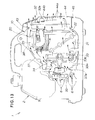
- a cooling system of the portable generator 1 will be described with reference to FIG. 13.
- the generator body 33 When the engine 20 of the generator unit 10 is started, the generator body 33 begins to generate electric power. This causes the cooling fan 34 to rotate in unison with the outer rotor 33c of the generator body 33.
- Rotation of the cooling fan 34 causes outside air to be drawn from the air inlets 6 into the case 2 and thence into the fan cover 37 through the air inlet 37a.
- the outside air is then forced or driven by the rotating cooling fan 37 to flow downstream through the fan cover 37, the shroud 38 and exhaust duct 44 to successively cool the generator body 33, the engine 20, the exhaust pipe 31 and the muffler 32.
- the outside air is exhausted from the vent holes 44a (exhaust hole 45) of the exhaust duct 44.
- the fan cover 35, shroud 38 and exhaust duct 44 connected end to end to form a single cooling passage.
- the cooling fan 34 is disposed in the cooling passage so that the outside air is drawn from the inlet 6, successively cools the generator body 33, engine 20, exhaust pipe 31 and muffler 32, and is finally exhausted from the exhaust hole 45 (vent holes 44a).
- the cooling system composed of a single cooling passage (formed by an in-line arrangement of the fan cover 34, shroud 38 and exhaust duct 44) and a single cooling fan 34 occupies only a small space within the case 2 and hence enables downsizing of the portable generator 1.
- a noise source formed by the generator body 33 and the cooling fan 34 associated therewith is enclosed in the fan cover 37.
- Another noise source formed by the engine 20 is enclosed in the shroud 38.
- the fan cover 37 containing the first noise source and the shroud 38 containing the second noise source are received in the case 2.
- the noise sources are doubly sound-insulated. With this double sound-insulating structure, the noise-proofing properties of the portable generator 1 are very high.
- the shroud 38 made of metal is directly attached to the engine 20, as shown in FIG. 5. Heat of an outer wall of the engine 20 is, therefore, directly transferred to the metal shroud 38.
- the metal shroud 38 directly attached to the engine 20 forms an effective radiating element and gives an additional heat-radiating surface to the engine 20.
- the engine 20 having such additional heat-radiating surface possesses a large cooling capacity or power and, hence, can be sufficiently cooled even when the cooling fan 34 is relatively small. Additionally, the use of the metal shroud 38 is contributive to the downsizing of the portable generator 1.
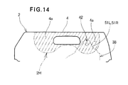
- FIG. 14 shows a modified form of the case 2 according to the present invention.
- the modified case which is also designated by 2 differs from the case 2 shown in FIGS. 1-13 only in that it includes a carrying handle 4 provided below an upper surface of the case 2 as a part of a body of the case 2.
- the shroud 38 is attached to an upper case portion 2H (including the carrying handle 4 and the reinforced mounting portion 4a of the carrying handle 4) indicated by phantom-lined hatching for clarity. With this arrangement, the weight of the shroud 38 can be effectively supported even when the carrying handle 4 does not project from the upper surface of the case 2.
- the metal shroud 38 which is directly attached to the case 2 to increase heat-radiating capacity or power of the engine 20 is preferably formed from a material having a large thermal conductivity (heat-transfer coefficient), such as a steel sheet or an aluminum plate.
- a steel plate having large stiffness is much preferable from a load-bearing point of view because the engine 20 accommodated within the shroud 38 is heavy.
- the shroud 38 may be attached to a body of the carrying handle 4 rather than to the root (reinforced mounting portion) 4a of the handle 4.
- socket portions 4b, 4c, 4c of the case 2 and the legs 54a, 64a, 64a of the generator unit 10 may take another form as long as they can fit with each other
- the right lower cushion member 71R and the left lower cushion member 71L may be integral with each other.
- a portable generator (1) comprises a shroud (38) for covering at least a crankcase (21) and a cylinder block (22) of an engine (20) thereof.
- the shroud is formed of split halves.
- the engine is fixed to the shroud having its upper part connected to a carrying handle (4) of a sound insulating case (2).
- the load of the engine is applied to the carrying handle through the shroud when the portable generator is lifted up with a hand. It is thus not necessary to increase rigidity of the case, thereby enabling lightening of the case.
- the generator arrangement also provides an improved soundproof effect since the engine, a source of noise, is covered with the shroud and the sound insulating case.
Abstract
Description
- The present invention relates to an engine and a portable generator having an engine and a generator body driven by the engine and accommodated within a sound insulating case together with the engine.
- A known portable generator includes an engine and a generator body driven by the engine, both being accommodated within a sound insulating case with a carrying handle provided at an upper part thereof for allowing gripping so that the generator can be hand-carried from one place to another. The sound insulating case needs to have increased rigidity, because it must support the heavy engine and generator body accommodated therein when the generator is lifted up for transportation by an operator's hand holding the carrying handle. However, it is quite difficult to increase rigidity of the sound insulating case without increasing the weight of the latter.
- An example portable generator in which this is taken into consideration is proposed in, for example, Japanese Patent Post-Exam Publication No. HEI-1-21399 entitled "PORTABLE GENERATOR". The proposed generator comprises a frame unit consisting of a pair of right and left frame members connected in spaced relation to each other via a lower-positioned bottom cover and an upper-positioned carrying handle, an accommodating case comprised of plural soundproof covers arranged to surround the frame unit, and an engine and a generator body accommodated within the accommodating case.
- In the proposed portable generator thus arranged, since rigidity of the accommodating case is increased through the provision of the frame unit, the configuration of the case is restricted by the configuration of the frame unit, whereby freedom in designing the configuration of the case is limited. Further, since the relatively heavy frame unit is employed for increasing the rigidity of the case, there is a room for improvement to substantially reduce the weight of the case including the frame unit.
- It is therefore an object of the present invention to provide a portable generator having a carrying-handle-equipped case for accommodating an engine and a generator body, which case is made light in weight by reducing a burden of load to be born thereby and imparted with increased freedom of designing its configuration.
- According to an aspect of the present invention, there is provided a portable generator which comprises an engine, a generator body driven by the engine, a sound insulating case accommodating the engine and the generator body and having a carrying handle, and a cooling and ventilating shroud surrounding at least a crankcase and a cylinder block of the engine, the shroud comprising a split shroud composed of a pair of right and left shroud halves, the engine being fixed to the split shroud, the split shroud having an upper joined portion and a lower joined portion, at least the upper joined portion being accommodated in and connected to the sound insulating case.
- In the portable generator, the engine is fixed to the shroud having its upper part connected to the carrying handle formed integrally with an upper part of the case. Therefore, the load of the engine is applied to the carrying handle of the case through the shroud when the portable generator is lifted up with a hand. Thus, it is not necessary to increase rigidity of the case. In other words, by increasing rigidity of only one part of the case, the number of conventional parts required to improve structural rigidity of the case is made small to thereby lighten the case itself. Further, freedom for configuration designing and material selection of the case is not limited by a variety of parts for improving rigidity of the case, thereby improving such freedom. Therefore, the shroud serves as a support member for supporting the engine at the upper part of the sound insulating case. Moreover, since at least a crankcase and a cylinder of the engine are surrounded by the shroud and further accommodated within the case, the portable generator has a double sound insulating structure. Furthermore, since the shroud is composed of a pair of right and left split halves, the engine can be surrounded readily.
- Preferably, each of the upper and lower joined portions of the split shroud is accommodated in and connected to the sound insulating case via a vibration-proof member. This is advantageous in that vibration generated upon operation of the engine is attenuated by the vibration-proof member provided at the upper and lower joined portions of the shroud and hence the least vibration is transmitted to the sound insulating case. Further, an under cover, made of a steel plate, for carrying the engine part on the case by means of the vibration-proof member, as required in a conventional arrangement, becomes unnecessary.
- Desirably, the split shroud is formed of a steel plate while the sound insulating case is formed of a synthetic resin. This is advantageous in that the split shroud is imparted with rigidity sufficient for supporting the engine and generator body. Further, it becomes possible to reduce the weight of the case and the cost of production of the same.
- In a preferred form, the sound insulating case includes a lower part having rigidity larger than that of the other part thereof. This makes it unnecessary to improve the rigidity of the entire case, whereby lightening of the case itself is enabled.
- The generator body may be disposed at an entrance side of the shroud. A muffler for the engine may be disposed at an exit side of the shroud. The generator body may comprise a magneto generator having an outer rotor driven by the engine. The generator body may include a cooling fan mounted to the outer rotor for taking external air through an intake port of the case into the shroud and discharging the air from the case after cooling an outer periphery of the engine and then the muffler.
- In other words, air introduced into the case through the intake port thereof enters into the shroud through an opening provided inside the case to thereby cool an outer peripheral of the engine and then cool the muffler. Thereafter, the air is discharged from the case through an exhaust port of the case. As a result, it becomes possible to efficiently cool the generator body, the engine and the muffler with the one cooling fan alone.
- A preferred embodiment of the present invention will be describe below, by way of example only, with reference to the accompanying drawings, in which:
- FIG. 1 is a perspective view of a portable generator according to an embodiment of the present invention;
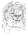
- FIG. 2 is a vertical cross-sectional view of the portable generator shown in FIG. 1;
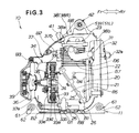
- FIG. 3 is a side view, with parts in cross section, of a generator unit of the portable generator shown in FIG. 2;
- FIG. 4 is an exploded perspective view of the generator unit shown in FIG. 3;
- FIG. 5 is an enlarged cross-sectional view taken along line V-V of FIG. 2;
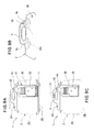
- FIG. 6 is an enlarged cross-sectional view showing a shroud hanger attachment structure shown in FIG. 5;
- FIG. 7 is an enlarged cross-sectional view taken along line VII-VII of FIG. 2;
- FIG. 8 is an enlarged cross-sectional view taken along line VIII-VIII of FIG. 2;
- FIGS. 9A, 9B and 9C are diagrammatical views showing the relationship between a sound insulating case and the generator unit;
- FIG. 10 is an enlarged cross-sectional view taken along line X-X of FIG. 2;
- FIG. 11 is an exploded perspective view of a right intermediate cushion member piece and its peripheral components shown in FIG. 10;
- FIG. 12 is an exploded perspective view illustrative of the manner in which the portable generator of FIG. 2 is assembled;
- FIG. 13 is a diagrammatical view showing the flow of cooling air inside the portable generator shown in FIG. 2; and
- FIG. 14 is a fragmentary side view showing a modified form of the carrying handle of the portable generator shown in FIG. 1.
-
- In some drawing figures, profiled arrows Fr, Rr, L and R are used to indicated respectively the forward, rearward, leftward and rightward directions of a
portable generator 1 embodying the present invention. - As shown in FIG. 1, the
portable generator 1 has a soundinsulating case 2. The sound insulatingcase 2 is made from a synthetic resin and has four legs 3 (two being shown) at the bottom adjacent to respective corners for setting or installation of theportable generator 1. Acarrying handle 4 for enabling hand-carrying transportation of theportable generator 1 is formed integrally with a transverse central portion of the upper surface of the sound insulatingcase 2. The sound insulatingcase 2 has a front face on which acontrol panel 5 is provided. A plurality ofair inlets 6 are formed in a front portion of each sidewall of the sound insulatingcase 2 for introducing outside air into the sound insulatingcase 2. - The sound insulating
case 2 including thecarrying handle 4 is composed of right and left case halves ormembers left case members carrying handle 4 while the other two screws at a rear end portion C and an intermediate portion D of a lower part of the sound insulatingcase 2. - The
carrying handle 4 has a generally inverted U shape elongated in the longitudinal direction of the sound insulatingcase 2 to secure adequate hand gripping by the user. Thecarrying handle 4 is composed of right and left handle halves ormembers left case members - In FIG. 1
reference numeral 7 denotes a side cover, andnumeral 8 denotes a lid for enabling inspection of a spark plug. - As shown in FIG. 2, the sound
insulating case 2 of theportable generator 1 accommodates within it agenerator unit 10, a controlunit accommodating box 72 and afuel tank 74. The controlunit accommodating box 72 and thefuel tank 74 are disposed forwardly of thegenerator unit 10. - FIGS. 3 and 4 show in detail the structure of the
generator unit 10. As shown in these figures, thegenerator unit 10 generally comprises anengine 20, abase 11 for supporting thereon theengine 20, amuffler 32 connected through anexhaust pipe 31 to theengine 20, agenerator body 33 assembled with theengine 20, a coolingfan 34 assembled with thegenerator body 33 and rotatable for drawing outside air, arecoil starter 36 connected by a connectingshaft 35 to the coolingfan 34, afan cover 37 surrounding thegenerator body 33 and the coolingfan 34, and a cooling and ventilatingshroud 38 covering or enclosing theengine 20 and a part of themuffler 32. - The
base 11 is comprised of an elongated rectangular steel plate and secured by three bolts B1 to three legs 26 (two being shown) provided on the bottom of theengine 10. Thebase 11 has a pair oftubular members - The
engine 20 is a single cylinder valve-in-head engine and includes acrankcase 21, acylinder block 22 and ahead cover 23 assembled together. Theengine 20 has anoutput shaft 24 extending horizontally. Thecrankcase 21 and thecylinder block 22 are bolted together along flanged mating surfaces 25 (Fig. 3) extending obliquely to an axis of theoutput shaft 24. - The
muffler 32 has a generally box-like shape and is attached to a rear face of thecylinder block 22. Themuffler 32 has anexhaust port 32a opening at a rear surface thereof. - The
generator body 33 is a permanent-magnet outer rotor generator or magneto having anouter rotor 33c driven for rotation by theengine 20. Thus, theportable generator 1 is an engine-driven generator. - The
generator body 33 includes acore 33a mounted to thecylinder block 22, a plurality of coils 33b wound around thecore 33a, the aforesaidouter rotor 33c having a cup-shaped configuration and mounted on theoutput shaft 24 of theengine 20, and a plurality ofpermanent magnets 33d fixed to an inner circumferential surface of the cup-shapedouter rotor 33c. - The
outer rotor 33c is designed to surround thecore 33a and the coils 33b, and the cooling fan (fan rotor) 34 is carried on a front face of theouter rotor 33c. Since theouter rotor 33c to which the coolingfan 34 is attached is highly rigid and has a large diameter, the coolingfan 34 is allowed to have a large diameter and can be easily and reliably attached to theouter rotor 33c. The use of such large-diameter cooling fan 34 enable creation of a large quantity of air which is sufficient to cool theengine 20 and thegenerator body 33. Additionally, because theouter rotor 33c serves also as a flywheel of theengine 20, no separate flywheel is needed. The internal space of the soundinsulating case 2 can, therefore, be reduced correspondingly, enabling downsizing of the portable generator 1 (FIG. 1). - The
output shaft 24 of theengine 20, theouter rotor 33c, the coolingfan 34, and therecoil starter 36 are coaxial with each other. Theouter rotor 33c has aventilating hole 33e. - The
fan cover 37 has a generally bowl-like shape and is attached to the engine 20 (more particularly, thecrankcase 21 and the cylinder block 22) by a plurality of stud bolts B2. The bowl-shapedfan cover 37 has acircular air inlet 37a at the bottom (left end in FIGS. 3 and 4) for introducing air into thefan cover 37, and a recoilstarter supporting cap 39 attached to thefan cover 37 in front of theair inlet 37a, there being a clearance (not designated) between the recoilstarter supporting cap 39 and thefan cover 37 so that the air can be drawn into thefan cover 37 through the clearance and theair inlet 37a connected to the clearance. The bowl-shapedfan cover 37 has anair outlet 37b at the open top end (right end in FIGS. 3 and 4) for letting the air out from thefan cover 37. Theair outlet 37b is directly connected to aninlet 38a of theshroud 38 by a fit joint formed between the open right end of thefan cover 37 and an open inlet side end (left end in FIGS. 3 and 4) of theshroud 38. - To secure efficient cooling of the
engine 20 inside the sound insulating case 2 (FIG. 2) while providing enhanced sound insulating effect, theshroud 38 is so designed as to cover or enclose at least thecrankcase 21 and thecylinder block 22 of theengine 20, and preferably substantially the whole body of theengine 20 as in the illustrated embodiment. Theshroud 38 is formed from a steel plate and has high stiffness properties. Theengine 20 is directly mounted to suchstiff shroud 38 by means of a plurality of screws B4, B5, B6 and B7 in such a manner that it is accommodated within theshroud 38.Reference numeral 41 shown in FIG. 3 denotes a spark plug mounting socket. - The
generator unit 10 has ahanger portion 42 at the top and a pair of front and rearbase mounting portions - Referring back to FIG. 2, the
hanger portion 42 of theshroud 38 is connected to a reinforced mountingportion 4a (root or base of the carrying handle 4) at a rear end of the invertedU-shaped carrying handle 4. The reinforced mountingportion 4a supports thegenerator unit 10 via theshroud 38 which serves also as a hanger for thegenerator unit 10. - The
base 11 is attached to a lower portion of thecase 2 via thebase mounting portions generator unit 10 is born by the lower portion of thecase 2. - An
exhaust duct 44 is attached to anexhaust hole 45 formed at a rear end of thecase 2 and covers or encloses a part of themuffler 32. Theexhaust duct 44 has a rear wall formed with a multiplicity of vent holes comprised ofslits 44a for venting the air from thecase 2, and an engine exhaust opening 44b for discharging the engine exhaust gases emitted from theexhaust port 32a of themuffler 32. - As shown in FIG. 5, the
shroud 38 is a split two-piece shroud composed of right and left shroud halves ormembers shroud members engine 20 inside theshroud 38, part of a sidewall of theshroud 38 is fastened by the screws B4, B5, B6, B7 to plural internally threadedprojections 27 formed on thecylinder block 22 of theengine 20. Since theshroud 38 of steel plate has a large heat-transfer coefficient (thermal conductivity), and since theengine 20 is directly attached to theshroud 38, heat from theengine 20 while running can be smoothly and rapidly transferred to theshroud 38 and radiated therefrom. Theshroud 38 is received in thecase 2 with itshanger portion 42 attached to thecase 2. In FIG. 5 designated by 46 is a carburetor equipped with a governor. - FIG. 6 shows an attachment structure of the
hanger portion 42 of theshroud 38. As shown in this figure, thehanger portion 42 is attached to thecase 2 by gripping thehanger portion 42 between the right and lefthandle members portion 4a formed by the root of the carryinghandle 4. - More specifically, the
hanger portion 42 includes a right hanging strip or lug 51R extending upwardly from an upper end portion of theright shroud member 38R, an annularright retaining portion 52R integral with theright hanging lug 51R and projecting therefrom in a lateral outward direction, an annular first right vibration-proof member 53R press-fitted with theright retaining portion 52R, a left hanging strip or lug 51L extending upwardly from an upper end portion of theleft shroud member 38L, an annularleft retaining projection 52L integral with theleft hanging lug 51L and projecting therefrom in a lateral outward direction, an annular first left vibration-proof member 53L press-fitted with theleft retaining projection 52L, ahorizontal hanging pin 54 press-fitted incentral holes 53a of the right and left vibration-proof members right washer 55R and aleft washer 55L fitted aroundopposite end portions pin 54 to prevent the right and left vibration-proof members projections - The
opposite end portions pin 54 project from outer ends of the right and left vibration-proof members end portions generator unit 10 to thecase 2 through the first vibration-proof members first legs - The right and left
handle members tubular socket portion 4b projecting interiorly and horizontally from the reinforced mountingportion 4a for snugly receiving therein one of thefirst legs - In assembly, the
socket portions first legs socket portions pin 54 and the first right and left vibration-proof members socket portions washers proof members case 2 can stably support the generator unit 10 (FIG. 5) by gripping thegenerator unit 10 via the vibration-proof members - The first right and left vibration-
proof members shroud members shroud 38 are mounted to thecase 2 via the first right and left vibration-proof members shroud 38 by means of the first right and left vibration-proof members - According to a modification of the present invention, the
hanger portion 42 of theshroud 38 may be attached to thecase 2 by fitting together thesocket portions case 2 and thefirst legs hanger pin 54 with the first right and left vibration-proof members socket portions legs proof members - Referring now to FIG. 7, there is shown a joint structure between the right and left
handle members left handle member 4L and is threaded into a nut B10 which is embedded in theright handle member 4R. The joint structure using the threaded fastener B9, B10 is formed at each of the rear and front end portions A, B (FIG. 1) of the carryinghandle 4. - FIG. 8 shows in detail the structure of the
base mounting portions portions 61 is comprised of thetubular member 62 carried on, and extending transversely of, thebase 11, a pair of annular second right and left vibration-proof members tubular member 62, a hollow ortubular support pin 64 press-fitted in respectivecentral holes proof members right washer 65R and aleft washer 65L fitted aroundopposite end portions support pin 64 to prevent removal of the second right and left vibration-proof members tubular member 62 and thesupport pin 64. - The
opposite end portions support pin 64 project from outer ends of the second right and left vibration-proof members opposite end portions proof members second legs - The right and left
case members tubular socket portion 4c extending interiorly and horizontally at abottom portion 2B of thecase 2 for fitting engagement with a corresponding one of thesecond legs support pin 64. Thebottom portion 2B has a relatively high stiffness. - In assembly, the
socket portions second legs tubular member 62 is supported by thesocket portions support pin 64 and the second right and left vibration-proof members tubular member 62 is gripped between opposed front ends of thesocket portions washers proof members case 2 stably supports the generator unit 10 (FIG. 2) by gripping thegenerator unit 10 via the vibration-proof members - The second right and left vibration-
proof members shroud 38 by means of the second right and left vibration-proof members - The
base mounting portions 61 may be modified to include a pair of second right and left vibration-proof members (not shown) which are attached in advance to thesocket portions second legs socket portions - The right and left
case members bottom portion 2B of the case by means of a threaded fastener which is composed of a screw B11 and a nut B12. The nut 12 is embedded in thesocket portion 4c of theright case member 2R. The screw B11 extends through thesocket portion 4c of theleft case member 2L and thesupport pin 64 and is threaded into the nut B12 to fasten the right and leftcase members case 2. - FIGS. 9A - 9C show the relationship between the
case 2 and thegenerator unit 10. - As shown in FIG. 9A, the
generator unit 10 is mounted to thecase 2 in such a way that theshroud 38 surrounding theengine 20 and bolted to opposite sides of theengine 20 is attached to the reinforced mountingportion 4a of the carryinghandle 4, and the base 11 carrying thereon theengine 20 and bolted to theengine 20 is attached to thebottom portion 2B of thecase 2 which has a relatively high stiffness. - As shown in FIG. 9B, a
top portion 2H of the case 2 (including the carryinghandle 4 and the reinforced mountingportions portion 2H must sustain the weight of components, such as theshroud 38, thegenerator unit 10 and the like, hanging from thesame portion 2H. Similarly, thebottom portion 2B (FIG. 9A) of thecase 2 is made stiffer than other portions because it is subjected to the weight of components contained in thecase 2. - As shown in FIG. 9C, when the user is carrying the
portable generator 1 from one place to another with the carryinghandle 4 gripped with its hand H, the weight of thegenerator unit 10 including theengine 20 mostly acts through theshroud 38 on the reinforced mountingportion 4a and thence on the carryinghandle 4. Theshroud 38 has a high stiffness and serves also as a support member (hanger) for supporting or hanging theengine 20 from the reinforced mountingportion 4a. With this mounting structure, aside portion 2S of thecase 2 is not so requested to bear the weight of thegenerator unit 10. - As is apparent from the foregoing description, when the
portable generator 1 is being hand-carried by the user, most of the weight of thegenerator unit 10 including theengine 20 acts on the top andbottom portions case 2. Taking this into consideration, theside portion 2S of thecase 2 may be constructed to have only a small stiffness. There is no need to increase the stiffness throughout the whole body of thecase 2, and so considerable weight reductions of thecase 2 become possible. Additionally, theportable generator 1 of the present invention, as opposed to the conventional apparatus, requires no frames to hold thecase 2 and, hence, is free from limitations resulting from the presence of the frames. Thus, thecase 2 has a high degree of flexibility not only in terms of the geometric design but also in terms of the selection of materials used. - Additionally, because at least the
crankcase 21 and thecylinder block 22 of theengine 20 are covered or shrouded doubly by theshroud 38 and thecase 2, an enhanced sound-insulating effect can be obtained. - Furthermore, since the
shroud 38 doubles in function as a shroud for cooling and ventilating theengine 20 and also as a support member (hanger) of theengine 20, the internal structure of theportable generator 1 can be simplified. - Referring now to FIG. 10, there is shown the control
unit accommodating box 72 and thefuel tank 74 stably held in position within thecase 2. - As shown in FIG. 10, a pair of right and left
lower cushion members bottom surface 2a of thecase 2 for supporting thereon the controlunit accommodating box 72. An intermediate cushion member 73 (composed of aright piece 73R and aleft piece 73L separated from each other) is associated with upper right and left corner portions of the controlunit accommodating box 72. Theintermediate cushion member 73 supports thereon thefuel tank 74. Thefuel tank 74 has a tubularfuel filler port 74a formed at its upper end and projecting upwardly and outwardly from an upper portion of thecase 2. - The control
unit accommodating box 72 is a relatively stiff rectangular box and accommodates within it a control unit (not shown) for controlling theengine 20 andgenerator body 33 shown in FIG. 2. The control unit accommodating box 72 (hereinafter referred to as "accommodating box") has a pair of right andleft legs lateral projection 72b at an upper right corner. The right andleft legs bottom surface 2a of thecase 2 via thelower cushion members legs lower cushion members guide grooves bottom surface 2a of thecase 2. Thelegs lower cushion members guide grooves accommodating box 72 relative to thecase 2 can be adjusted in the transverse direction of thecase 2. - The
fuel tank 74 further has a pair ofpositioning projections 74b formed integrally with and projecting horizontally from lower right and left corners of thefuel tank 74. An annularupper cushion member 75 is fitted around a root or base portion of thefuel filler port 74a. Afiller cap 76 is attached to an upper end of thefuel filler port 74a to close thefuel filler port 74a. - The
case 2 has anupper hole 2c formed at mating surfaces of the right and leftcase members upper cushion member 75 is also fitted in theupper hole 2c so that thefuel filler port 74a is supported by an inner edge of theupper hole 2c with theupper cushion member 75 disposed therebetween. - The
right piece 73R of theintermediate cushion member 73 is attached by press-fitting to a portion of the inner surface of a sidewall of theright case member 2R. Similarly, theleft piece 73L of theintermediate cushion member 73 is attached by press-fitting to a portion of the inner surface of a sidewall of theleft case member 2L. A joint structure between the right and left intermediatecushion member pieces case members - The right and left intermediate
cushion member pieces vertical base portion 73a and ahorizontal wing portion 73b. Thesepieces respective wing portions - The opposed
horizontal wing portions accommodating box 72 and a lower surface of thefuel tank 74. A total weight of theaccommodating box 72 andfuel tank 74 is applied via thelower cushion members horizontal wing portions bottom portion 2B (FIG. 8) ofcase 2 which is made stiffer than other portions. - The
vertical base portion 73a of the right intermediatecushion member piece 73R has formed therein an upper recessed portion 73C for positioning thefuel tank 74, and a lower recessedportion 73d for positioning theaccommodating box 72. The left intermediatecushion member piece 73L has a recessedportion 73c formed in thevertical base portion 73a for positioning thefuel tank 74. - The
base portion 73a of the left intermediatecushion member piece 73L is held in direct contact with a left side surface of theaccommodating box 72, and the lower recessedportion 73d of the right intermediatecushion member piece 73R is fitted with thepositioning projection 72b of theaccommodating box 72 so that the right and leftcase members accommodating box 72 in position by gripping theaccommodating box 72 at the upper right and left corners via the right and left intermediatecushing member pieces - Similarly, the recessed
portions cushion member pieces positioning projections fuel tank 74 so that the right and leftcase members fuel tank 74 in position by gripping thefuel tank 74 at the lower right and left corners via the right and left intermediatecushing member pieces - The
lower cushion members upper cushion member 74 are made from an elastic material such as rubber. - As appears clear from the foregoing description, the
accommodating box 72 holding therein the control unit (not shown) is carried via thelower cushion members bottom portion 2B (FIG. 8) ofcase 2 which is made stiffer than other portions of thecase 2, andfuel tank 74 is mounted on theaccommodating box 72 via theintermediate cushion member 73. By using such simple two-storied arrangement, the fuel tank 72 (which becomes heavy when filled) can be readily accommodated within an upper part of thecase 2. Additionally, thefuel filler port 74a projecting from an upper portion of thecase 2 insures easy filling of the fuel to thefuel tank 74 accommodated within thecase 2. - The weight of the
fuel tank 71 is applied to thebottom surface 2a of thebottom portion 2B (FIG. 8) through theintermediate cushion member 73, the relatively stiffaccommodating box 72 and thelower cushion member 71. Since the weight of thefuel tank 74 is born by the relatively stiffaccommodating box 72, and since vibrations and shocks are damped by the lower andintermediate cushion members case 2. Instead, partial stiffening of thecase 2, as done at the top andbottom portions case 2 and provides a higher degree of flexibility in designing the geometric shape of thecase 2 and selecting materials used for thecase 2, as compared to the conventional structural means taken to increase the stiffness of the case. - The right and
left cover members accommodating box 72 and opposite sidewalls of thefuel tank 74 through the right and left intermediatecushion member pieces accommodating box 72 and thefuel tank 74 are stably held in position within thecase 2. Since theaccommodating box 72 and thefuel tank 74 are automatically brought to a final attachment position when they are gripped as just described above, an attachment structure of theaccommodating box 72 andfuel box 74 relative to thecase 2 is very simple in construction. Furthermore, horizontal vibrations and shocks tending to act on theaccommodating box 72 and thefuel tank 74 are sufficiently damped by the right and left intermediatecushion member pieces - At the
upper hole 2c of thecase 2, thefuel filler port 74a of thefuel tank 74 is gripped by the right and leftcase member upper cushion member 75 disposed between thefuel filler port 74a and the inner edge of theupper hole 2c. Thus, thefuel tank 74 is stably and reliably attached to thecase 2. - Referring now to FIG. 11, there is shown in exploded perspective a joint structure used for attaching the right
intermediate cushion member 73R to theright cover member 2R shown in FIG. 10. - The
right cover member 2R includes pair of spaced retainingprojections cover member 2R. The retainingprojections - The right intermediate
cushion member piece 73R has a pair of spaced lockingrecesses projections projections projections cushion member piece 73R to theright case member 2R. - The right intermediate
cushion member piece 73R has a pair of parallel spacedribs 73f formed integrally with an upper surface of thehorizontal wing portion 73b. Theribs 73f are triangular in cross section and has a ridge of an acute angle. Theribs 73f support thereon a lower surface of thefuel tank 74 and they are elastically deformable to an extent proportional to the quantity of fuel held in thefuel tank 74. - A joint structure used for attaching the left
intermediate cushion member 73L (FIG. 10) to theleft cover member 2L (FIG. 10) is the same as the joint structure just described above with reference to FIG. 11, and a further description thereof can be omitted. - A sequence of processing steps taken to assemble the
portable generator 1 of the foregoing construction will be described with reference to FIG. 12. The processing steps should be construed as illustrative and not restrictive. - At first, the
right case member 2R having a innerinner control panel 82 screwed thereto in advance is set in an assembling site with the inside surface of the sidewall (or the mating surface) facing upwards. The right intermediatecushion member piece 73R is also attached in advance to theright cover member 2R. - Then, the
generator unit 10 while kept in a half-rolled position above theright cover member 2R is placed down onto theright cover member 2R so that the rightfirst leg 54a and the rightsecond legs generator unit 10 are fitted in thesocket portions right case member 2R. - Subsequently, the
lower cushion members legs accommodating box 72. - Thereafter, the
accommodating box 72 while kept in a half-rolled position above theright cover member 2R is placed down onto theright cover member 2R such that the rightlower cushion member 71R is fitted into thepositioning groove 2b of theright case member 2R, and thepositioning projection 72b of theaccommodating box 72 is fitted in the recessedportion 73d of the right intermediatecushion member piece 73R. - Then, the
fuel tank 74 while kept in a half-rolled position above theright cover member 2R is placed down onto theright cover member 2R such that thepositioning projection 74b of thefuel tank 74 is fitted in the recessedportion 73c of the right intermediatecushion member piece 73R. - Subsequently, the
left cover member 2L having the left intermediatecushion member piece 73L attached thereto in advance is placed down onto theright cover member 2R while the inside surface of the sidewall (or the mating surface) of theleft cover member 2L facing downwards. - Thereafter, the
left cover member 2L is mated with theright cover member 2R such that the leftfirst leg 54a and the leftsecond legs generator unit 10 are fitted into thesocket portions left cover member 2L. During that time, thepositioning groove 2b of theleft cover member 2L fittingly receives therein the leftlower cushion member 71L, and the left intermediatecushion member piece 73L is brought into abutment with the left sidewall of theaccommodating box 72. In this instance, the recessedportion 73c of the left intermediatecushion member piece 73L is fitted with thepositioning projection 74b of thefuel tank 74. - Then, the left and
right case members inner control panel 82 is firmly secured by a screw (not shown) to theleft cover member 2L. - Subsequently,
seal members 81 and thecontrol panel 5 are placed over theinner control pane 82 through a front opening of thecover 2, and thecontrol panel 5 is secured by a screw B13 to theinner control panel 82 with theseal members 81 disposed between the twopanels - Then, seal
members 43 are fitted on theexhaust duct 44 and after that theexhaust duct 44 is inserted into theexhaust hole 45 until it is fitted with theoutlet 38b of theshroud 38 with theseal members 43 disposed therebetween. Theexhaust duct 44 is secured by screws B14 (one being shown) to thecase 2. Aportable generator 1 of the present invention is thus completed. - As will be understood from the foregoing description, the
portable generator 1 can be built up by merely assembling together theright case member 2R, thegenerator unit 10, theaccommodating box 72, thefuel tank 74 and theleft case member 2L from one direction in the order described above. Such unidirectional assembling operations do not involve frequent changes in position and posture of the components which are tedious and time-consuming. Accordingly, the efficiency of the assembling process is veery high. - Additionally, by virtue of the fitting engagement between the
legs generator unit 10 and thesocket portions case members case members generator unit 10 are temporarily assembled together with thegenerator unit 10 stably held therebetween. The number of portions to be joined together by screws can, therefore, be reduced and the assembling efficiency increases further. - A cooling system of the
portable generator 1 will be described with reference to FIG. 13. - When the
engine 20 of thegenerator unit 10 is started, thegenerator body 33 begins to generate electric power. This causes the coolingfan 34 to rotate in unison with theouter rotor 33c of thegenerator body 33. - Rotation of the cooling
fan 34 causes outside air to be drawn from theair inlets 6 into thecase 2 and thence into thefan cover 37 through theair inlet 37a. The outside air is then forced or driven by the rotating coolingfan 37 to flow downstream through thefan cover 37, theshroud 38 andexhaust duct 44 to successively cool thegenerator body 33, theengine 20, theexhaust pipe 31 and themuffler 32. After cooling of thecomponents vent holes 44a (exhaust hole 45) of theexhaust duct 44. - The
fan cover 35,shroud 38 andexhaust duct 44 connected end to end to form a single cooling passage. The coolingfan 34 is disposed in the cooling passage so that the outside air is drawn from theinlet 6, successively cools thegenerator body 33,engine 20,exhaust pipe 31 andmuffler 32, and is finally exhausted from the exhaust hole 45 (ventholes 44a). - The cooling system composed of a single cooling passage (formed by an in-line arrangement of the
fan cover 34,shroud 38 and exhaust duct 44) and asingle cooling fan 34 occupies only a small space within thecase 2 and hence enables downsizing of theportable generator 1. - A noise source formed by the
generator body 33 and the coolingfan 34 associated therewith is enclosed in thefan cover 37. Another noise source formed by theengine 20 is enclosed in theshroud 38. Thefan cover 37 containing the first noise source and theshroud 38 containing the second noise source are received in thecase 2. Thus, the noise sources are doubly sound-insulated. With this double sound-insulating structure, the noise-proofing properties of theportable generator 1 are very high. - Description given below is directed to the cooling capacity or power of the
engine 20. - The
shroud 38 made of metal (steel plate in the illustrated embodiment) is directly attached to theengine 20, as shown in FIG. 5. Heat of an outer wall of theengine 20 is, therefore, directly transferred to themetal shroud 38. Themetal shroud 38 directly attached to theengine 20 forms an effective radiating element and gives an additional heat-radiating surface to theengine 20. Theengine 20 having such additional heat-radiating surface possesses a large cooling capacity or power and, hence, can be sufficiently cooled even when the coolingfan 34 is relatively small. Additionally, the use of themetal shroud 38 is contributive to the downsizing of theportable generator 1. - FIG. 14 shows a modified form of the
case 2 according to the present invention. The modified case, which is also designated by 2, differs from thecase 2 shown in FIGS. 1-13 only in that it includes a carryinghandle 4 provided below an upper surface of thecase 2 as a part of a body of thecase 2. In this embodiment, theshroud 38 is attached to anupper case portion 2H (including the carryinghandle 4 and the reinforced mountingportion 4a of the carrying handle 4) indicated by phantom-lined hatching for clarity. With this arrangement, the weight of theshroud 38 can be effectively supported even when the carryinghandle 4 does not project from the upper surface of thecase 2. - The
metal shroud 38 which is directly attached to thecase 2 to increase heat-radiating capacity or power of theengine 20 is preferably formed from a material having a large thermal conductivity (heat-transfer coefficient), such as a steel sheet or an aluminum plate. A steel plate having large stiffness is much preferable from a load-bearing point of view because theengine 20 accommodated within theshroud 38 is heavy. Theshroud 38 may be attached to a body of the carryinghandle 4 rather than to the root (reinforced mounting portion) 4a of thehandle 4. - Furthermore, the
socket portions case 2 and thelegs generator unit 10 may take another form as long as they can fit with each other Additionally, the rightlower cushion member 71R and the leftlower cushion member 71L may be integral with each other. - A portable generator (1) comprises a shroud (38) for covering at least a crankcase (21) and a cylinder block (22) of an engine (20) thereof. The shroud is formed of split halves. The engine is fixed to the shroud having its upper part connected to a carrying handle (4) of a sound insulating case (2). As a result, the load of the engine is applied to the carrying handle through the shroud when the portable generator is lifted up with a hand. It is thus not necessary to increase rigidity of the case, thereby enabling lightening of the case. The generator arrangement also provides an improved soundproof effect since the engine, a source of noise, is covered with the shroud and the sound insulating case.
Claims (6)
- A portable generator (1) comprising:an engine (20);a generator body (33) driven by said engine (20);a sound insulating case (2) accommodating said engine (20) and said generator body (33) and having a carrying handle (4); anda cooling and ventilating shroud (38) surrounding at least a crankcase (21) and a cylinder block (22) of said engine (20), said shroud (38) comprising a split shroud composed of a pair of right and left shroud halves (38R, 38L),said engine being fixed to said split shroud,said split shroud having an upper joined portion and a lower joined portion, at least said upper joined portion being accommodated in and connected to said sound insulating case.
- The portable generator of claim 1, wherein each of said upper and lower joined portions of said split shroud is accommodated in and connected to said sound insulating case via a vibration-proof member (53L, 53R; 63L, 63R).
- The portable generator of claim 1, wherein said split shroud is formed of a steel plate and said sound insulating case is formed of a synthetic resin.
- The portable generator of claim 2, wherein said split shroud is formed of a steel plate and said sound insulating case is formed of a synthetic resin.
- The portable generator of claim 1, wherein said sound insulating case includes a lower part (2B) having rigidity larger than that of the other part thereof.
- The portable generator of claim 1, wherein said generator body is disposed at an entrance side of said shroud, a muffler (32) for said engine is disposed at an exit side of said shroud, said generator body comprises a magneto generator having an outer rotor (33c) driven by said engine, and said generator body includes a cooling fan (34) mounted to said outer rotor for taking external air through an intake port (6) of said case into said shroud and discharging the air from said case after cooling an outer periphery of said engine and then said muffler.
Applications Claiming Priority (2)
| Application Number | Priority Date | Filing Date | Title |
|---|---|---|---|
| JP2263098 | 1998-01-19 | ||
| JP02263098A JP3347044B2 (en) | 1998-01-19 | 1998-01-19 | Portable engine working machine |
Publications (3)
| Publication Number | Publication Date |
|---|---|
| EP0931920A2 true EP0931920A2 (en) | 1999-07-28 |
| EP0931920A3 EP0931920A3 (en) | 2000-03-15 |
| EP0931920B1 EP0931920B1 (en) | 2003-04-16 |
Family
ID=12088157
Family Applications (1)
| Application Number | Title | Priority Date | Filing Date |
|---|---|---|---|
| EP99100828A Expired - Lifetime EP0931920B1 (en) | 1998-01-19 | 1999-01-18 | Portable generator |
Country Status (5)
| Country | Link |
|---|---|
| US (1) | US6091160A (en) |
| EP (1) | EP0931920B1 (en) |
| JP (1) | JP3347044B2 (en) |
| CN (1) | CN1120932C (en) |
| DE (1) | DE69906834T2 (en) |
Cited By (6)
| Publication number | Priority date | Publication date | Assignee | Title |
|---|---|---|---|---|
| EP1124046A2 (en) * | 2000-02-09 | 2001-08-16 | Fuji Jukogyo Kabushiki Kaisha | Engine generator |
| EP1146212A3 (en) * | 2000-04-14 | 2002-10-23 | Fuji Jukogyo Kabushiki Kaisha | Engine generator |
| US6849961B2 (en) * | 2001-09-03 | 2005-02-01 | Honda Giken Kogyo Kabushiki Kaisha | Engine generator |
| EP1995431A1 (en) * | 2007-05-22 | 2008-11-26 | Yunfeng Ma | Portable generator |
| EP3219953A1 (en) * | 2016-03-16 | 2017-09-20 | Honda Motor Co., Ltd. | Engine-driven working machine |
| EP3885549A4 (en) * | 2019-01-21 | 2021-11-10 | Honda Motor Co., Ltd. | Power generation device |
Families Citing this family (39)
| Publication number | Priority date | Publication date | Assignee | Title |
|---|---|---|---|---|
| US6608393B2 (en) * | 1997-02-28 | 2003-08-19 | Clifton Gerard Anderson | Portable DC power generator with constant voltage |
| JP2000328957A (en) * | 1999-05-21 | 2000-11-28 | Honda Motor Co Ltd | Engine power generator |
| JP3886002B2 (en) | 2002-03-27 | 2007-02-28 | ヤマハ発動機株式会社 | Engine generator |
| US6917121B2 (en) * | 2002-03-29 | 2005-07-12 | Yamaha Hatsudoki Kabushiki Kaisha | Power generator unit |
| US6971399B2 (en) * | 2003-01-10 | 2005-12-06 | Cowan Leroy Frank | Emergency supply system to supplant interrupted public and private utilities |
| US7482705B2 (en) * | 2003-05-12 | 2009-01-27 | Piercey Iii Gerald S | Generator support plenum |
| US20080129053A1 (en) * | 2004-05-12 | 2008-06-05 | Piercey Gerald S | Engine-generator set |
| JP2006097582A (en) | 2004-09-29 | 2006-04-13 | Honda Motor Co Ltd | Portable engine work machine |
| JP4530830B2 (en) | 2004-12-15 | 2010-08-25 | ヤマハモーターパワープロダクツ株式会社 | Engine generator |
| JP4484691B2 (en) * | 2004-12-22 | 2010-06-16 | ヤマハモーターパワープロダクツ株式会社 | Engine generator |
| JP2006188980A (en) | 2005-01-06 | 2006-07-20 | Yamaha Motor Co Ltd | Engine type generator |
| MY144502A (en) * | 2005-06-23 | 2011-09-30 | Honda Motor Co Ltd | Multipurpose engine |
| CN1815001A (en) * | 2006-03-08 | 2006-08-09 | 无锡开普动力有限公司 | Portable generator |
| US7859124B2 (en) * | 2006-08-16 | 2010-12-28 | Andreas Stihl Ag & Co. Kg | Internal combustion engine with alternator |
| CN1945932A (en) * | 2006-10-17 | 2007-04-11 | 马云峰 | Portable generator |
| US7492050B2 (en) | 2006-10-24 | 2009-02-17 | Briggs & Stratton Corporation | Cooling system for a portable generator |
| JP2008255831A (en) * | 2007-04-02 | 2008-10-23 | Yamaha Motor Powered Products Co Ltd | Soundproof engine generator |
| JP4974155B2 (en) * | 2007-04-02 | 2012-07-11 | ヤマハモーターパワープロダクツ株式会社 | Sound insulation type engine generator |
| US7699027B2 (en) * | 2007-08-17 | 2010-04-20 | Yunfeng Ma | Portable generator |
| JP5146912B2 (en) | 2008-05-23 | 2013-02-20 | 日立工機株式会社 | Chainsaw |
| US8899378B2 (en) | 2011-09-13 | 2014-12-02 | Black & Decker Inc. | Compressor intake muffler and filter |
| AU2012216660B2 (en) | 2011-09-13 | 2016-10-13 | Black & Decker Inc | Tank dampening device |
| JP5915485B2 (en) * | 2012-03-15 | 2016-05-11 | 日立工機株式会社 | Engine working machine |
| US8960708B2 (en) | 2012-11-30 | 2015-02-24 | Kohler Co. | Enclosure guide system for a towable generator |
| CN103291447B (en) * | 2013-05-24 | 2015-10-21 | 宁波顶和电子有限公司 | A kind of Intelligent oil-saving portable power generation unit |
| US10294858B2 (en) | 2013-08-29 | 2019-05-21 | Polaris Industries Inc. | Portable generator |
| JP5985691B1 (en) * | 2015-03-26 | 2016-09-06 | 本田技研工業株式会社 | Engine driven generator |
| JP6030686B2 (en) * | 2015-03-26 | 2016-11-24 | 本田技研工業株式会社 | Engine driven generator |
| JP5986252B1 (en) * | 2015-03-26 | 2016-09-06 | 本田技研工業株式会社 | Engine driven generator |
| US11111913B2 (en) | 2015-10-07 | 2021-09-07 | Black & Decker Inc. | Oil lubricated compressor |
| JP1592658S (en) * | 2017-08-31 | 2018-09-03 | ||
| USD856930S1 (en) * | 2017-10-18 | 2019-08-20 | Shi Sheng Huang | Portable power generator |
| USD872018S1 (en) * | 2017-12-05 | 2020-01-07 | Zhengchao Dong | Power supply |
| JP6773921B2 (en) * | 2017-12-11 | 2020-10-21 | 本田技研工業株式会社 | Engine equipment |
| USD894834S1 (en) * | 2018-09-12 | 2020-09-01 | Caterpillar Inc. | Generator |
| CN109989826A (en) * | 2019-04-15 | 2019-07-09 | 重庆华世丹动力科技股份有限公司 | Generating set cooling air duct construction |
| USD930587S1 (en) * | 2020-04-07 | 2021-09-14 | Fna Group, Inc. | Portable generator |
| JP1706158S (en) * | 2021-07-09 | 2022-01-27 | Motor generator | |
| CN114483294B (en) * | 2022-01-11 | 2024-01-23 | 重庆乾威科技有限公司 | Tool type generator handle |
Citations (1)
| Publication number | Priority date | Publication date | Assignee | Title |
|---|---|---|---|---|
| JPS6421399A (en) | 1987-06-18 | 1989-01-24 | Westinghouse Electric Corp | Fuel rod takeoff apparatus, withdrawal of fuel rod, capacity reducer, use of extrusion rod and transfer of fuel rod |
Family Cites Families (10)
| Publication number | Priority date | Publication date | Assignee | Title |
|---|---|---|---|---|
| GB986740A (en) * | 1962-10-24 | 1965-03-24 | Honda Gijutsu Kenkyusho Kk | Improvements in or relating to portable internal combustion engines |
| DE3410976A1 (en) * | 1983-03-18 | 1984-10-04 | Honda Giken Kogyo K.K., Tokio/Tokyo | COMPLETELY ENCLOSED, PORTABLE GENERATOR |
| GB2141782B (en) * | 1983-05-11 | 1987-01-07 | Honda Motor Co Ltd | Portable engine-generator sets |
| JPH0128270Y2 (en) * | 1984-10-09 | 1989-08-29 | ||
| US4647835A (en) * | 1984-12-19 | 1987-03-03 | Kawasaki Jukogyo Kabushiki Kaisha | Portable generator |
| US4859886A (en) * | 1986-02-28 | 1989-08-22 | Honda Giken Kogyo Kabushiki Kaisha | Portable engine-operated electric generator |
| US4827147A (en) * | 1986-11-12 | 1989-05-02 | Honda Giken Kogyo Kabushiki Kaisha | Engine-powered portable working apparatus |
| FR2659113B1 (en) * | 1990-03-02 | 1992-06-12 | Lombardini France | PORTABLE ASSEMBLY COMBINING A HEAT ENGINE AND A MACHINE, FOR EXAMPLE GENERATOR. |
| JP2901774B2 (en) * | 1990-04-13 | 1999-06-07 | ヤマハ発動機株式会社 | Engine driven generator |
| JPH0622028A (en) * | 1992-06-30 | 1994-01-28 | Fujitsu Ltd | Management system in communication network |
-
1998
- 1998-01-19 JP JP02263098A patent/JP3347044B2/en not_active Expired - Lifetime
-
1999
- 1999-01-15 US US09/232,470 patent/US6091160A/en not_active Expired - Lifetime
- 1999-01-18 DE DE69906834T patent/DE69906834T2/en not_active Expired - Lifetime
- 1999-01-18 EP EP99100828A patent/EP0931920B1/en not_active Expired - Lifetime
- 1999-01-19 CN CN99100615.1A patent/CN1120932C/en not_active Expired - Lifetime
Patent Citations (1)
| Publication number | Priority date | Publication date | Assignee | Title |
|---|---|---|---|---|
| JPS6421399A (en) | 1987-06-18 | 1989-01-24 | Westinghouse Electric Corp | Fuel rod takeoff apparatus, withdrawal of fuel rod, capacity reducer, use of extrusion rod and transfer of fuel rod |
Cited By (9)
| Publication number | Priority date | Publication date | Assignee | Title |
|---|---|---|---|---|
| EP1124046A2 (en) * | 2000-02-09 | 2001-08-16 | Fuji Jukogyo Kabushiki Kaisha | Engine generator |
| EP1124046A3 (en) * | 2000-02-09 | 2002-10-23 | Fuji Jukogyo Kabushiki Kaisha | Engine generator |
| EP1146212A3 (en) * | 2000-04-14 | 2002-10-23 | Fuji Jukogyo Kabushiki Kaisha | Engine generator |
| EP1520967A1 (en) * | 2000-04-14 | 2005-04-06 | Fuji Jukogyo Kabushiki Kaisha | Engine generator |
| US6849961B2 (en) * | 2001-09-03 | 2005-02-01 | Honda Giken Kogyo Kabushiki Kaisha | Engine generator |
| EP1995431A1 (en) * | 2007-05-22 | 2008-11-26 | Yunfeng Ma | Portable generator |
| EP3219953A1 (en) * | 2016-03-16 | 2017-09-20 | Honda Motor Co., Ltd. | Engine-driven working machine |
| US10260456B2 (en) | 2016-03-16 | 2019-04-16 | Honda Motor Co., Ltd. | Engine-driven working machine |
| EP3885549A4 (en) * | 2019-01-21 | 2021-11-10 | Honda Motor Co., Ltd. | Power generation device |
Also Published As
| Publication number | Publication date |
|---|---|
| US6091160A (en) | 2000-07-18 |
| EP0931920A3 (en) | 2000-03-15 |
| EP0931920B1 (en) | 2003-04-16 |
| CN1224114A (en) | 1999-07-28 |
| DE69906834D1 (en) | 2003-05-22 |
| JPH11200875A (en) | 1999-07-27 |
| CN1120932C (en) | 2003-09-10 |
| DE69906834T2 (en) | 2004-01-15 |
| JP3347044B2 (en) | 2002-11-20 |
Similar Documents
| Publication | Publication Date | Title |
|---|---|---|
| EP0931920B1 (en) | Portable generator | |
| EP0931919B1 (en) | Portable generator | |
| US4827147A (en) | Engine-powered portable working apparatus | |
| AU2004255716B2 (en) | Engine-driven electric generator | |
| US6378469B1 (en) | Engine generating machine | |
| KR100348872B1 (en) | Engine operated machine | |
| JP3815703B2 (en) | Engine generator | |
| AU2004255629B2 (en) | Engine-driven working machine | |
| JP3753529B2 (en) | Engine generator | |
| US20030070651A1 (en) | Soundproofed engine generator | |
| EP3219952B1 (en) | Engine-driven working machine | |
| JP3315639B2 (en) | Portable engine working machine | |
| US11143139B2 (en) | Engine device | |
| JP3340665B2 (en) | Engine working machine | |
| JP3340666B2 (en) | Portable engine working machine | |
| US4773365A (en) | Chain saw | |
| JP3871829B2 (en) | Engine generator | |
| JPH02291417A (en) | Air-cooled engine | |
| JP2010007598A (en) | Engine-driven power generator |
Legal Events
| Date | Code | Title | Description |
|---|---|---|---|
| PUAI | Public reference made under article 153(3) epc to a published international application that has entered the european phase |
Free format text: ORIGINAL CODE: 0009012 |
|
| AK | Designated contracting states |
Kind code of ref document: A2 Designated state(s): DE FR GB IT |
|
| AX | Request for extension of the european patent |
Free format text: AL;LT;LV;MK;RO;SI |
|
| PUAL | Search report despatched |
Free format text: ORIGINAL CODE: 0009013 |
|
| AK | Designated contracting states |
Kind code of ref document: A3 Designated state(s): AT BE CH CY DE DK ES FI FR GB GR IE IT LI LU MC NL PT SE |
|
| AX | Request for extension of the european patent |
Free format text: AL;LT;LV;MK;RO;SI |
|
| 17P | Request for examination filed |
Effective date: 20000405 |
|
| AKX | Designation fees paid |
Free format text: DE FR GB IT |
|
| 17Q | First examination report despatched |
Effective date: 20020124 |
|
| GRAH | Despatch of communication of intention to grant a patent |
Free format text: ORIGINAL CODE: EPIDOS IGRA |
|
| GRAH | Despatch of communication of intention to grant a patent |
Free format text: ORIGINAL CODE: EPIDOS IGRA |
|
| GRAA | (expected) grant |
Free format text: ORIGINAL CODE: 0009210 |
|
| AK | Designated contracting states |
Designated state(s): DE FR GB IT |
|
| REG | Reference to a national code |
Ref country code: GB Ref legal event code: FG4D |
|
| REF | Corresponds to: |
Ref document number: 69906834 Country of ref document: DE Date of ref document: 20030522 Kind code of ref document: P |
|
| ET | Fr: translation filed | ||
| PLBE | No opposition filed within time limit |
Free format text: ORIGINAL CODE: 0009261 |
|
| STAA | Information on the status of an ep patent application or granted ep patent |
Free format text: STATUS: NO OPPOSITION FILED WITHIN TIME LIMIT |
|
| 26N | No opposition filed |
Effective date: 20040119 |
|
| REG | Reference to a national code |
Ref country code: FR Ref legal event code: PLFP Year of fee payment: 18 |
|
| REG | Reference to a national code |
Ref country code: FR Ref legal event code: PLFP Year of fee payment: 19 |
|
| REG | Reference to a national code |
Ref country code: FR Ref legal event code: PLFP Year of fee payment: 20 |
|
| PGFP | Annual fee paid to national office [announced via postgrant information from national office to epo] |
Ref country code: FR Payment date: 20171211 Year of fee payment: 20 |
|
| PGFP | Annual fee paid to national office [announced via postgrant information from national office to epo] |
Ref country code: GB Payment date: 20180117 Year of fee payment: 20 Ref country code: DE Payment date: 20180103 Year of fee payment: 20 |
|
| PGFP | Annual fee paid to national office [announced via postgrant information from national office to epo] |
Ref country code: IT Payment date: 20180122 Year of fee payment: 20 |
|
| REG | Reference to a national code |
Ref country code: DE Ref legal event code: R071 Ref document number: 69906834 Country of ref document: DE |
|
| REG | Reference to a national code |
Ref country code: GB Ref legal event code: PE20 Expiry date: 20190117 |
|
| PG25 | Lapsed in a contracting state [announced via postgrant information from national office to epo] |
Ref country code: GB Free format text: LAPSE BECAUSE OF EXPIRATION OF PROTECTION Effective date: 20190117 |