EP0931684A1 - Vehicle, particularly electrically driven vehicle - Google Patents
Vehicle, particularly electrically driven vehicle Download PDFInfo
- Publication number
- EP0931684A1 EP0931684A1 EP99200128A EP99200128A EP0931684A1 EP 0931684 A1 EP0931684 A1 EP 0931684A1 EP 99200128 A EP99200128 A EP 99200128A EP 99200128 A EP99200128 A EP 99200128A EP 0931684 A1 EP0931684 A1 EP 0931684A1
- Authority
- EP
- European Patent Office
- Prior art keywords
- vehicle
- housing
- wheel
- yoke
- electric motor
- Prior art date
- Legal status (The legal status is an assumption and is not a legal conclusion. Google has not performed a legal analysis and makes no representation as to the accuracy of the status listed.)
- Granted
Links
- 239000000725 suspension Substances 0.000 claims abstract description 40
- 230000005540 biological transmission Effects 0.000 claims abstract description 32
- 230000033001 locomotion Effects 0.000 abstract description 6
- 230000008878 coupling Effects 0.000 abstract description 4
- 238000010168 coupling process Methods 0.000 abstract description 4
- 238000005859 coupling reaction Methods 0.000 abstract description 4
- 238000009434 installation Methods 0.000 description 6
- 239000006096 absorbing agent Substances 0.000 description 2
- 230000035939 shock Effects 0.000 description 2
- 238000010276 construction Methods 0.000 description 1
- 239000000498 cooling water Substances 0.000 description 1
Images


Classifications
-
- B—PERFORMING OPERATIONS; TRANSPORTING
- B60—VEHICLES IN GENERAL
- B60K—ARRANGEMENT OR MOUNTING OF PROPULSION UNITS OR OF TRANSMISSIONS IN VEHICLES; ARRANGEMENT OR MOUNTING OF PLURAL DIVERSE PRIME-MOVERS IN VEHICLES; AUXILIARY DRIVES FOR VEHICLES; INSTRUMENTATION OR DASHBOARDS FOR VEHICLES; ARRANGEMENTS IN CONNECTION WITH COOLING, AIR INTAKE, GAS EXHAUST OR FUEL SUPPLY OF PROPULSION UNITS IN VEHICLES
- B60K7/00—Disposition of motor in, or adjacent to, traction wheel
- B60K7/0007—Disposition of motor in, or adjacent to, traction wheel the motor being electric
-
- B—PERFORMING OPERATIONS; TRANSPORTING
- B60—VEHICLES IN GENERAL
- B60G—VEHICLE SUSPENSION ARRANGEMENTS
- B60G3/00—Resilient suspensions for a single wheel
- B60G3/01—Resilient suspensions for a single wheel the wheel being mounted for sliding movement, e.g. in or on a vertical guide
-
- B—PERFORMING OPERATIONS; TRANSPORTING
- B60—VEHICLES IN GENERAL
- B60G—VEHICLE SUSPENSION ARRANGEMENTS
- B60G3/00—Resilient suspensions for a single wheel
- B60G3/18—Resilient suspensions for a single wheel with two or more pivoted arms, e.g. parallelogram
- B60G3/20—Resilient suspensions for a single wheel with two or more pivoted arms, e.g. parallelogram all arms being rigid
-
- B—PERFORMING OPERATIONS; TRANSPORTING
- B60—VEHICLES IN GENERAL
- B60G—VEHICLE SUSPENSION ARRANGEMENTS
- B60G2200/00—Indexing codes relating to suspension types
- B60G2200/10—Independent suspensions
- B60G2200/14—Independent suspensions with lateral arms
- B60G2200/144—Independent suspensions with lateral arms with two lateral arms forming a parallelogram
-
- B—PERFORMING OPERATIONS; TRANSPORTING
- B60—VEHICLES IN GENERAL
- B60G—VEHICLE SUSPENSION ARRANGEMENTS
- B60G2200/00—Indexing codes relating to suspension types
- B60G2200/40—Indexing codes relating to the wheels in the suspensions
- B60G2200/422—Driving wheels or live axles
-
- B—PERFORMING OPERATIONS; TRANSPORTING
- B60—VEHICLES IN GENERAL
- B60G—VEHICLE SUSPENSION ARRANGEMENTS
- B60G2200/00—Indexing codes relating to suspension types
- B60G2200/40—Indexing codes relating to the wheels in the suspensions
- B60G2200/44—Indexing codes relating to the wheels in the suspensions steerable
-
- B—PERFORMING OPERATIONS; TRANSPORTING
- B60—VEHICLES IN GENERAL
- B60G—VEHICLE SUSPENSION ARRANGEMENTS
- B60G2202/00—Indexing codes relating to the type of spring, damper or actuator
- B60G2202/10—Type of spring
- B60G2202/15—Fluid spring
- B60G2202/152—Pneumatic spring
- B60G2202/1524—Pneumatic spring with two air springs per wheel, arranged before and after the wheel axis
-
- B—PERFORMING OPERATIONS; TRANSPORTING
- B60—VEHICLES IN GENERAL
- B60G—VEHICLE SUSPENSION ARRANGEMENTS
- B60G2204/00—Indexing codes related to suspensions per se or to auxiliary parts
- B60G2204/10—Mounting of suspension elements
- B60G2204/12—Mounting of springs or dampers
- B60G2204/126—Mounting of pneumatic springs
-
- B—PERFORMING OPERATIONS; TRANSPORTING
- B60—VEHICLES IN GENERAL
- B60G—VEHICLE SUSPENSION ARRANGEMENTS
- B60G2204/00—Indexing codes related to suspensions per se or to auxiliary parts
- B60G2204/10—Mounting of suspension elements
- B60G2204/14—Mounting of suspension arms
- B60G2204/148—Mounting of suspension arms on the unsprung part of the vehicle, e.g. wheel knuckle or rigid axle
-
- B—PERFORMING OPERATIONS; TRANSPORTING
- B60—VEHICLES IN GENERAL
- B60G—VEHICLE SUSPENSION ARRANGEMENTS
- B60G2204/00—Indexing codes related to suspensions per se or to auxiliary parts
- B60G2204/10—Mounting of suspension elements
- B60G2204/14—Mounting of suspension arms
- B60G2204/148—Mounting of suspension arms on the unsprung part of the vehicle, e.g. wheel knuckle or rigid axle
- B60G2204/1484—Mounting of suspension arms on the unsprung part of the vehicle, e.g. wheel knuckle or rigid axle on an intermediate upright strut upon which the stub axle is pivoted
-
- B—PERFORMING OPERATIONS; TRANSPORTING
- B60—VEHICLES IN GENERAL
- B60G—VEHICLE SUSPENSION ARRANGEMENTS
- B60G2206/00—Indexing codes related to the manufacturing of suspensions: constructional features, the materials used, procedures or tools
- B60G2206/01—Constructional features of suspension elements, e.g. arms, dampers, springs
- B60G2206/50—Constructional features of wheel supports or knuckles, e.g. steering knuckles, spindle attachments
-
- B—PERFORMING OPERATIONS; TRANSPORTING
- B60—VEHICLES IN GENERAL
- B60G—VEHICLE SUSPENSION ARRANGEMENTS
- B60G2300/00—Indexing codes relating to the type of vehicle
- B60G2300/14—Buses
-
- B—PERFORMING OPERATIONS; TRANSPORTING
- B60—VEHICLES IN GENERAL
- B60G—VEHICLE SUSPENSION ARRANGEMENTS
- B60G2300/00—Indexing codes relating to the type of vehicle
- B60G2300/38—Low or lowerable bed vehicles
-
- B—PERFORMING OPERATIONS; TRANSPORTING
- B60—VEHICLES IN GENERAL
- B60K—ARRANGEMENT OR MOUNTING OF PROPULSION UNITS OR OF TRANSMISSIONS IN VEHICLES; ARRANGEMENT OR MOUNTING OF PLURAL DIVERSE PRIME-MOVERS IN VEHICLES; AUXILIARY DRIVES FOR VEHICLES; INSTRUMENTATION OR DASHBOARDS FOR VEHICLES; ARRANGEMENTS IN CONNECTION WITH COOLING, AIR INTAKE, GAS EXHAUST OR FUEL SUPPLY OF PROPULSION UNITS IN VEHICLES
- B60K17/00—Arrangement or mounting of transmissions in vehicles
- B60K17/04—Arrangement or mounting of transmissions in vehicles characterised by arrangement, location or kind of gearing
- B60K17/043—Transmission unit disposed in on near the vehicle wheel, or between the differential gear unit and the wheel
- B60K17/046—Transmission unit disposed in on near the vehicle wheel, or between the differential gear unit and the wheel with planetary gearing having orbital motion
-
- B—PERFORMING OPERATIONS; TRANSPORTING
- B60—VEHICLES IN GENERAL
- B60K—ARRANGEMENT OR MOUNTING OF PROPULSION UNITS OR OF TRANSMISSIONS IN VEHICLES; ARRANGEMENT OR MOUNTING OF PLURAL DIVERSE PRIME-MOVERS IN VEHICLES; AUXILIARY DRIVES FOR VEHICLES; INSTRUMENTATION OR DASHBOARDS FOR VEHICLES; ARRANGEMENTS IN CONNECTION WITH COOLING, AIR INTAKE, GAS EXHAUST OR FUEL SUPPLY OF PROPULSION UNITS IN VEHICLES
- B60K7/00—Disposition of motor in, or adjacent to, traction wheel
- B60K2007/0038—Disposition of motor in, or adjacent to, traction wheel the motor moving together with the wheel axle
-
- B—PERFORMING OPERATIONS; TRANSPORTING
- B60—VEHICLES IN GENERAL
- B60K—ARRANGEMENT OR MOUNTING OF PROPULSION UNITS OR OF TRANSMISSIONS IN VEHICLES; ARRANGEMENT OR MOUNTING OF PLURAL DIVERSE PRIME-MOVERS IN VEHICLES; AUXILIARY DRIVES FOR VEHICLES; INSTRUMENTATION OR DASHBOARDS FOR VEHICLES; ARRANGEMENTS IN CONNECTION WITH COOLING, AIR INTAKE, GAS EXHAUST OR FUEL SUPPLY OF PROPULSION UNITS IN VEHICLES
- B60K7/00—Disposition of motor in, or adjacent to, traction wheel
- B60K2007/0061—Disposition of motor in, or adjacent to, traction wheel the motor axle being parallel to the wheel axle
-
- B—PERFORMING OPERATIONS; TRANSPORTING
- B60—VEHICLES IN GENERAL
- B60K—ARRANGEMENT OR MOUNTING OF PROPULSION UNITS OR OF TRANSMISSIONS IN VEHICLES; ARRANGEMENT OR MOUNTING OF PLURAL DIVERSE PRIME-MOVERS IN VEHICLES; AUXILIARY DRIVES FOR VEHICLES; INSTRUMENTATION OR DASHBOARDS FOR VEHICLES; ARRANGEMENTS IN CONNECTION WITH COOLING, AIR INTAKE, GAS EXHAUST OR FUEL SUPPLY OF PROPULSION UNITS IN VEHICLES
- B60K7/00—Disposition of motor in, or adjacent to, traction wheel
- B60K2007/0092—Disposition of motor in, or adjacent to, traction wheel the motor axle being coaxial to the wheel axle
-
- B—PERFORMING OPERATIONS; TRANSPORTING
- B60—VEHICLES IN GENERAL
- B60L—PROPULSION OF ELECTRICALLY-PROPELLED VEHICLES; SUPPLYING ELECTRIC POWER FOR AUXILIARY EQUIPMENT OF ELECTRICALLY-PROPELLED VEHICLES; ELECTRODYNAMIC BRAKE SYSTEMS FOR VEHICLES IN GENERAL; MAGNETIC SUSPENSION OR LEVITATION FOR VEHICLES; MONITORING OPERATING VARIABLES OF ELECTRICALLY-PROPELLED VEHICLES; ELECTRIC SAFETY DEVICES FOR ELECTRICALLY-PROPELLED VEHICLES
- B60L2200/00—Type of vehicles
- B60L2200/26—Rail vehicles
-
- B—PERFORMING OPERATIONS; TRANSPORTING
- B60—VEHICLES IN GENERAL
- B60L—PROPULSION OF ELECTRICALLY-PROPELLED VEHICLES; SUPPLYING ELECTRIC POWER FOR AUXILIARY EQUIPMENT OF ELECTRICALLY-PROPELLED VEHICLES; ELECTRODYNAMIC BRAKE SYSTEMS FOR VEHICLES IN GENERAL; MAGNETIC SUSPENSION OR LEVITATION FOR VEHICLES; MONITORING OPERATING VARIABLES OF ELECTRICALLY-PROPELLED VEHICLES; ELECTRIC SAFETY DEVICES FOR ELECTRICALLY-PROPELLED VEHICLES
- B60L2220/00—Electrical machine types; Structures or applications thereof
- B60L2220/40—Electrical machine applications
- B60L2220/46—Wheel motors, i.e. motor connected to only one wheel
Definitions
- the invention relates to a vehicle, specifically an electrically driven vehicle, comprising a number of driven wheels each of which is supported on bearings in a housing that is connected to the rest of the vehicle via supporting arms ofa wheel suspension, which wheels can be driven by an electric motor via a transmission, whereby the electric motor and the transmission are present in a space present in the vehicle for the wheel suspension.
- This space for the wheel suspension is usually the space in the wheel housing ofthe vehicle.
- the electric motor and the transmission can be integrated in the specified housing or they can be positioned in the vicinity ofthe wheel to be driven in the wheel housing and fastened to the body of the vehicle.
- the wheel housing can be made smaller and the electric motor with transmission can be installed on the interior of the vehicle against the wheel housing.
- the space just outside the wheel housing, on the inside of the vehicle should also be considered to comprise the specified space for the wheel suspension.
- Such drive constructions are compact in structure and are utilized in vehicles in which the available installation space is limited or where power transport from the power source to the driven wheels via a mechanical route is not desirable, for example due to a low floor that would even make it impossible to mechanically couple the drive shafts of two wheels to each other on the same shaft, or because there is a great distance between the wheels being driven.
- Wheel suspensions in which the wheel is fastened to the vehicle by supporting arms are utilized for vehicles in which the wheels must have a broad range of motion in order, for example, to compensate for a very uneven road and/or very sharp curves. Since in the interest ofthe environment electrical drive systems are becoming increasingly desirable, more and more types of vehicles are being designed with electrical drive systems.
- a vehicle of the type as described in the preamble is known from the American patent specification US 5.004.061.
- vehicle the ends ofthe supporting arms of the wheel suspension are connected in a hinged manner with the housing in which the wheel shaft rests on bearings and in which the drive and transmission are located.
- the other ends of the supporting arms are connected with hinges to the vehicle, which in this case is a golf cart. Thanks to the great amount of available space the wheel suspension can be installed without any problems.
- An objective of the invention is to produce a vehicle of the type as described in the preamble in which the structure of the suspension and of the drive of the wheel is more compact and requires less installation space than the wheel suspension of the known vehicle.
- the vehicle according to the invention is characterized by the fact that the wheel suspension comprises a yoke that is connected with the housing whereby an end of each supporting arm is connected in a hinged manner to the yoke. By utilizing a yoke the connection points with the supporting arms can be shifted, facilitating a more compact structure.
- One embodiment of the vehicle according to the invention is characterized by the fact that the electric motor and the transmission are located in the housing. This results in a structure that is very compact.
- Another embodiment of the vehicle according to the invention is characterized by the fact that the electric motor and the transmission are located a distance from the housing and positioned in or near the wheel housing of the vehicle and fastened to the body of the vehicle, with the wheel shaft being connected with the transmission via a drive shaft.
- An additional advantage of this structure is that the electrical cables and possible cooling water hoses no longer need to move along with the wheel in terms of the body of the vehicle.
- the electric motor and transmission can be fastened directly or via auxiliary elements to the wheel housing.
- Another embodiment of the vehicle according to the invention is characterized by the fact that the yoke of the wheel suspension is connected in two places in a hinged manner with the housing, so that the housing forms a stub axle. This makes the wheel suspension also suitable for steerable wheels.
- An additional advantage of a yoke is the virtually vertical motion of the yoke at spring movements. So if an air spring bellows is used this would be less subject to wear and tear.
- each connection of the yoke with the housing contains a bush containing a swivel pin, with the possibility of the swivel pin and the bush being turned in relation to each other, and with the swivel pin being fastened to the housing or the yoke and the bush being fastened either in the yoke or in the housing.
- Yet another embodiment is characterized by the fact that the yoke is C-shaped, such that the top end of the yoke, when there is a wheel on the wheel shaft, is located above the wheel and the uppermost supporting arm is connected in a hinged manner with this end.
- the uppermost supporting arm By this placement ofthe uppermost supporting arm, the interior space in the vehicle between the wheels is considerably greater and the floor height in the interior between the wheels can remain low in comparison with the rest of the vehicle, so that the passengers can move freely in and out of the vehicle.
- Another embodiment associated with the previous one is characterized by the fact that, if the wheel suspension is built into a vehicle, the lower supporting arm, under the floor surface of the vehicle, is connected with the body of the vehicle. Preferably here the undermost supporting arm is connected with the vehicle near its longitudinal central surface.
- the yoke consists of at least two parts that are connected with each other such that they can be taken apart.
- the yoke is divided near the hinge point of the undermost supporting arm.
- another embodiment is characterized by the fact that the end of the wheel shaft extends from the housing on the side of the yoke, with a brake disc being attached to the specified protruding end.
- FIG. 1 shows a wheel suspension of a first embodiment of the vehicle according to the invention.
- the wheel suspension 1 is built into the wheel housing 3 ofthe vehicle.
- the wheel suspension 1 has a wheel 5 with a rim 7 upon which a tyre 9 is present.
- the rim 7 is attached with bolts to a flange 11 on a wheel shaft 13.
- the wheel shaft 13 is supported on bearings in a housing 15 and extends from the housing with an end 17. At this end 17 a brake disc 19 is fastened.
- the electric motor 21 In the housing 15 there is an electric motor 21 for the drive of the wheel 5.
- the electric motor 21 has a stator 23 that is fastened to the housing 15 and a rotor 25 that is fastened to a bush 27 supported on bearings on the wheel shaft 13.
- a transmission 29 that consists of a double planetary gearing.
- the bush 27 is toothed at the end and the teeth mesh with planet gears 31.
- the planet gears 31 are supported on bearings on a planet carrier 33, that is supported on bearings on the wheel shaft 13 and in its turn meshes with other planet gears 35 of the second transmission.
- the planet gears 35 are supported on bearings on another planet carrier 36 that is fastened to the wheel shaft 13.
- These supporting arms 55 are hinged with an end 57 to the yoke 37 and with another end 59 to the body 58 of the vehicle under the floor surface 60 near a longitudinal central surface 61 of the vehicle.
- the yoke 37 is divided into two parts near the hinge point with the lower supporting arm 55. The place where the two parts are connected with each other is indicated by arrow 63.
- the brake callipers with brake shoes have been omitted here.
- FIG 2 the wheel suspension 1 is shown from above.
- the yoke 37 is connected at its top end 47 with two upper supporting arms 49 and connected on the underside with two lower supporting arms 55.
- the two upper supporting arms 49 can also be in the form of a single unit. The same applies to the lower supporting arms 55.
- FIG 3 shows another embodiment ofthe housing that contains an electric motor and transmission.
- the electric motor 71 is approximately in the centre of the housing 73.
- the transmission 75 has two steps 77 and 79, with one being present on each side ofthe electric motor 71.
- the electric motor 71 has a stator 81 that is fastened to the housing 73 and a rotor 83 fastened to a revolving bush on bearings 85.
- the bush 85 forms the outgoing shaft of the electric motor and has a toothed end that meshes with the planet gears 87 of the first step 77.
- the planet gears 87 are on bearings on a planet carrier 89 that forms the outgoing shaft of the first step 77.
- the planet carrier 89 is formed by a hollow sleeve 91 provided with a flange 93 with a ring 94 connected to it that is on bearings on a wheel shaft 95.
- the planet gears 87 revolve around a shaft 96 that is fastened to the flange 93 and the ring 94.
- the sleeve 91 forms the outgoing shaft ofthe first step 77 as well as the incoming shaft of the second step 79, and it passes through the electric motor 71.
- On the other end the sleeve 91 has teeth that mesh with planet gears 97 of the second step 79.
- These planet gears 97 are on bearings on another planet carrier 99 that forms the outgoing shaft of the second step. This planet carrier 99 is finally fastened to the wheel shaft 95.
- Figure 4 shows a cross section of a wheel suspension 101 with a drive of a different embodiment of the vehicle according to the invention.
- the transmission 103 and the electric motor 105 are fastened against the wheel housing 107.
- the wheel 109 is on bearings with a wheel hub 110 in housing 113.
- the housing 113 is the stub axle of the wheel suspension.
- a brake disc 115 is fastened to the wheel hub 110.
- the wheel shaft 111 is coupled to the wheel hub 110.
- the wheel shaft 111 is coupled with the transmission 103 via a drive shaft 117.
- the coupling between the drive shaft 117 on the one hand and the wheel shaft 111 respectively the transmission 103 on the other is established by two homokinetic couplings 119 and 121.
- the transmission 103 is located against the wheel housing 107 and the coupling 121 can be integrated into a gear 123 so as to be able to use a relatively long drive shaft 117, allowing broad spring movements where there are only small angle differences in the drive shaft.
- Two swivel pins 125 and 127 are fastened to the housing 113 around which bushes 129 and 131 can revolve. These bushes are fastened to a C-shaped yoke 133 that is suspended in the vehicle via supporting arms 135 and 137. Between the yoke 133 and the wheel housing 107 there is a shock absorber 139 and an air spring bellows 141.
- Figure 5 shows a top view ofthe wheel suspension 101 with drive shown in figure 4.
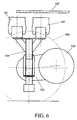
- the electric motor 105 is located beside the transmission 103 which is shown more clearly in figure 6.
- a simpler gear transmission can be utilized than a double planetary gearing.
- the wheel 109 is shown, for purposes of clarity, by a broken line.
- the vehicle can also comprise a subframe to which the supporting arms are connected with a hinge at the end.
- the subframe can then, in its turn, be attached to the body ofthe vehicle rather than the supporting arms being directly connected to the body of the vehicle.
Landscapes
- Engineering & Computer Science (AREA)
- Mechanical Engineering (AREA)
- Chemical & Material Sciences (AREA)
- Combustion & Propulsion (AREA)
- Transportation (AREA)
- Arrangement Or Mounting Of Propulsion Units For Vehicles (AREA)
- Vehicle Body Suspensions (AREA)
- Air-Conditioning For Vehicles (AREA)
- Treatment Of Sludge (AREA)
Abstract
Description
- The invention relates to a vehicle, specifically an electrically driven vehicle, comprising a number of driven wheels each of which is supported on bearings in a housing that is connected to the rest of the vehicle via supporting arms ofa wheel suspension, which wheels can be driven by an electric motor via a transmission, whereby the electric motor and the transmission are present in a space present in the vehicle for the wheel suspension. This space for the wheel suspension is usually the space in the wheel housing ofthe vehicle. The electric motor and the transmission can be integrated in the specified housing or they can be positioned in the vicinity ofthe wheel to be driven in the wheel housing and fastened to the body of the vehicle. However, for structural reasons the wheel housing can be made smaller and the electric motor with transmission can be installed on the interior of the vehicle against the wheel housing. In this case the space just outside the wheel housing, on the inside of the vehicle, should also be considered to comprise the specified space for the wheel suspension. Such drive constructions are compact in structure and are utilized in vehicles in which the available installation space is limited or where power transport from the power source to the driven wheels via a mechanical route is not desirable, for example due to a low floor that would even make it impossible to mechanically couple the drive shafts of two wheels to each other on the same shaft, or because there is a great distance between the wheels being driven. Wheel suspensions in which the wheel is fastened to the vehicle by supporting arms are utilized for vehicles in which the wheels must have a broad range of motion in order, for example, to compensate for a very uneven road and/or very sharp curves. Since in the interest ofthe environment electrical drive systems are becoming increasingly desirable, more and more types of vehicles are being designed with electrical drive systems.
- A vehicle of the type as described in the preamble is known from the American patent specification US 5.004.061. In that vehicle the ends ofthe supporting arms of the wheel suspension are connected in a hinged manner with the housing in which the wheel shaft rests on bearings and in which the drive and transmission are located. The other ends of the supporting arms are connected with hinges to the vehicle, which in this case is a golf cart. Thanks to the great amount of available space the wheel suspension can be installed without any problems.
- Whereas in the past electrical drive systems were utilized chiefly for rail vehicles, trolley buses, and golf carts, these days electrical drives are being used with increasing frequency in other types ofvehicles. Since in most vehicles it is desirable to keep the installation space as small as possible in connection with the maximal amount of space available for the passengers or the freight, the wheel suspension in combination with the possible wheel drive should be as compact as possible. The known wheel suspension demands too much installation space to be able to meet the standards of compactness in vehicles intended for the transport of persons and/or goods.
- An objective of the invention is to produce a vehicle of the type as described in the preamble in which the structure of the suspension and of the drive of the wheel is more compact and requires less installation space than the wheel suspension of the known vehicle. To this end the vehicle according to the invention is characterized by the fact that the wheel suspension comprises a yoke that is connected with the housing whereby an end of each supporting arm is connected in a hinged manner to the yoke. By utilizing a yoke the connection points with the supporting arms can be shifted, facilitating a more compact structure.
- Though it is true that wheel suspensions in which a yoke is utilized do already exist, a combination of such a wheel suspension with a drive located in the space in the vehicle meant for the wheel suspension is new. As a result of this new combination a wheel suspension with an electric motor and transmission is obtained that requires only a minimal amount of installation space and in which broad wheel motions are possible
- One embodiment of the vehicle according to the invention is characterized by the fact that the electric motor and the transmission are located in the housing. This results in a structure that is very compact.
- Another embodiment of the vehicle according to the invention is characterized by the fact that the electric motor and the transmission are located a distance from the housing and positioned in or near the wheel housing of the vehicle and fastened to the body of the vehicle, with the wheel shaft being connected with the transmission via a drive shaft. This results in a structure in which the unsprung weight is low yet requires minimal installation space. An additional advantage of this structure is that the electrical cables and possible cooling water hoses no longer need to move along with the wheel in terms of the body of the vehicle. The electric motor and transmission can be fastened directly or via auxiliary elements to the wheel housing.
- Another embodiment of the vehicle according to the invention is characterized by the fact that the yoke of the wheel suspension is connected in two places in a hinged manner with the housing, so that the housing forms a stub axle. This makes the wheel suspension also suitable for steerable wheels. An additional advantage of a yoke is the virtually vertical motion of the yoke at spring movements. So if an air spring bellows is used this would be less subject to wear and tear.
- Another advantage of using a yoke is that in the connection with the housing it is not necessary for ball hinges to be used. So another advantageous embodiment is characterized by the fact that each connection of the yoke with the housing contains a bush containing a swivel pin, with the possibility of the swivel pin and the bush being turned in relation to each other, and with the swivel pin being fastened to the housing or the yoke and the bush being fastened either in the yoke or in the housing.
- Yet another embodiment is characterized by the fact that the yoke is C-shaped, such that the top end of the yoke, when there is a wheel on the wheel shaft, is located above the wheel and the uppermost supporting arm is connected in a hinged manner with this end. By this placement ofthe uppermost supporting arm, the interior space in the vehicle between the wheels is considerably greater and the floor height in the interior between the wheels can remain low in comparison with the rest of the vehicle, so that the passengers can move freely in and out of the vehicle.
- Another embodiment associated with the previous one is characterized by the fact that, if the wheel suspension is built into a vehicle, the lower supporting arm, under the floor surface of the vehicle, is connected with the body of the vehicle. Preferably here the undermost supporting arm is connected with the vehicle near its longitudinal central surface.
- To simplify the assembly and disassembly of the wheel suspension another embodiment is characterized by the fact that the yoke consists of at least two parts that are connected with each other such that they can be taken apart. Preferably the yoke is divided near the hinge point of the undermost supporting arm.
- To be able to better utilize the available space in the wheel, another embodiment is characterized by the fact that the end of the wheel shaft extends from the housing on the side of the yoke, with a brake disc being attached to the specified protruding end. An advantage of this structure is that the brake pads and brake disc can be easily replaced without any need for the wheel to be removed.
- Another embodiment is characterized by the fact that the transmission present in the housing comprises at least two steps, one of which is present on each side of the electric motor. The outgoing shaft ofthe electric motor is fastened to the incoming shaft of one of the steps, with the outgoing shaft being hollow and going through the electric motor and being connected to the incoming shaft of the other step, the outgoing shaft of which is fastened to the wheel shaft that goes through the specified hollow shaft. Another embodiment is characterized by the fact that the vehicle comprises a subframe to which the supporting arms are hingedly connected with an end. For this reason the assembly of the wheel suspension can be done independently of the assembly of the vehicle for which the wheel suspension is intended, which may be efficient in terms of assembly. In addition using a subframe can contribute to the structure of the vehicle in terms of strength and rigidity.
- The invention will be elucidated more fully below by means of drawings in which different embodiments of the vehicle according to the invention are shown. In these drawings:
- Figure 1 shows a cross section of a wheel suspension and a drive of a first embodiment of the vehicle according to the invention;
- Figure 2 shows a top view of the wheel suspension and drive shown in figure 1;
- Figure 3 shows an electric motor and transmission of a second embodiment of the vehicle according to the invention;
- Figure 4 shows a cross section of a wheel suspension and a drive of a third embodiment of the vehicle according to the invention;
- Figure 5 shows a top view ofthe wheel suspension and drive shown in figure 4; and
- Figure 6 shows a side view of the wheel suspension and drive shown in figure 4.
-
- Figure 1 shows a wheel suspension of a first embodiment of the vehicle according to the invention. The
wheel suspension 1 is built into thewheel housing 3 ofthe vehicle. Thewheel suspension 1 has awheel 5 with arim 7 upon which atyre 9 is present. Therim 7 is attached with bolts to aflange 11 on awheel shaft 13. Thewheel shaft 13 is supported on bearings in ahousing 15 and extends from the housing with anend 17. At this end 17 abrake disc 19 is fastened. In thehousing 15 there is anelectric motor 21 for the drive of thewheel 5. Theelectric motor 21 has astator 23 that is fastened to thehousing 15 and a rotor 25 that is fastened to abush 27 supported on bearings on thewheel shaft 13. - In the
housing 15 there is also a transmission 29 that consists of a double planetary gearing. Thebush 27 is toothed at the end and the teeth mesh with planet gears 31. The planet gears 31 are supported on bearings on a planet carrier 33, that is supported on bearings on thewheel shaft 13 and in its turn meshes with other planet gears 35 of the second transmission. The planet gears 35 are supported on bearings on anotherplanet carrier 36 that is fastened to thewheel shaft 13. - The
housing 15 is connected to ayoke 37 in a hinged manner. The connection is formed byswivel pins housing 15 and can revolve inbushes yoke 37. Theyoke 37 is C-shaped. Thetop end 47 is located above thewheel 5 and is suspended to the vehicle via the upper supportingarms 49. These supportingarms 49 are hinged with anend 51 to theyoke 37 and with theother end 53 to the vehicle. On the underside theyoke 37 is suspended via the lower supportingarms 55 to the vehicle. These supportingarms 55 are hinged with anend 57 to theyoke 37 and with anotherend 59 to thebody 58 of the vehicle under thefloor surface 60 near a longitudinalcentral surface 61 of the vehicle. Theyoke 37 is divided into two parts near the hinge point with the lower supportingarm 55. The place where the two parts are connected with each other is indicated byarrow 63. Between theyoke 37 and thewheel housing 3 of the vehicle there is also ashock absorber 65 and an air spring bellows 67 and there is abrake booster 69 at the housing. For the sake of clarity the brake callipers with brake shoes have been omitted here. - In figure 2 the
wheel suspension 1 is shown from above. Here it is clearly visible that theyoke 37 is connected at itstop end 47 with two upper supportingarms 49 and connected on the underside with two lower supportingarms 55. Of course the two upper supportingarms 49 can also be in the form of a single unit. The same applies to the lower supportingarms 55. - Figure 3 shows another embodiment ofthe housing that contains an electric motor and transmission. The
electric motor 71 is approximately in the centre of thehousing 73. Thetransmission 75 has twosteps electric motor 71. Theelectric motor 71 has astator 81 that is fastened to thehousing 73 and arotor 83 fastened to a revolving bush onbearings 85. Thebush 85 forms the outgoing shaft of the electric motor and has a toothed end that meshes with the planet gears 87 of thefirst step 77. The planet gears 87 are on bearings on aplanet carrier 89 that forms the outgoing shaft of thefirst step 77. Theplanet carrier 89 is formed by ahollow sleeve 91 provided with aflange 93 with aring 94 connected to it that is on bearings on a wheel shaft 95. The planet gears 87 revolve around ashaft 96 that is fastened to theflange 93 and thering 94. Thesleeve 91 forms the outgoing shaft ofthefirst step 77 as well as the incoming shaft of thesecond step 79, and it passes through theelectric motor 71. On the other end thesleeve 91 has teeth that mesh with planet gears 97 of thesecond step 79. These planet gears 97 are on bearings on anotherplanet carrier 99 that forms the outgoing shaft of the second step. Thisplanet carrier 99 is finally fastened to the wheel shaft 95. - Figure 4 shows a cross section of a
wheel suspension 101 with a drive of a different embodiment of the vehicle according to the invention. Here thetransmission 103 and theelectric motor 105 are fastened against thewheel housing 107. Thewheel 109 is on bearings with awheel hub 110 inhousing 113. In this embodiment thehousing 113 is the stub axle of the wheel suspension. Abrake disc 115 is fastened to thewheel hub 110. Thewheel shaft 111 is coupled to thewheel hub 110. Thewheel shaft 111 is coupled with thetransmission 103 via adrive shaft 117. The coupling between thedrive shaft 117 on the one hand and thewheel shaft 111 respectively thetransmission 103 on the other is established by twohomokinetic couplings transmission 103 is located against thewheel housing 107 and thecoupling 121 can be integrated into agear 123 so as to be able to use a relativelylong drive shaft 117, allowing broad spring movements where there are only small angle differences in the drive shaft. Two swivel pins 125 and 127 are fastened to thehousing 113 around whichbushes yoke 133 that is suspended in the vehicle via supportingarms yoke 133 and thewheel housing 107 there is ashock absorber 139 and an air spring bellows 141. - Figure 5 shows a top view ofthe
wheel suspension 101 with drive shown in figure 4. For purposes of clarity the yoke and the supporting arms of the suspension are not shown here. Theelectric motor 105 is located beside thetransmission 103 which is shown more clearly in figure 6. By fastening thetransmission 103 and theelectric motor 105 against thewheel housing 107 one has more structural freedom than ifthese were integrated into thehousing 113 of thewheel shaft 111. In addition a simpler gear transmission can be utilized than a double planetary gearing. In figure 6 thewheel 109 is shown, for purposes of clarity, by a broken line. - Although above the invention is elucidated on the basis of the drawings, it should be established that the invention is in no way limited to the embodiments shown in the drawings. The invention also extends to all embodiments deviating from the embodiments shown in the drawings within the context defined by the claims. For example the vehicle can also comprise a subframe to which the supporting arms are connected with a hinge at the end. The subframe can then, in its turn, be attached to the body ofthe vehicle rather than the supporting arms being directly connected to the body of the vehicle.
Claims (13)
- Vehicle, specifically an electrically driven vehicle, comprising a number of driven wheels each of which is supported on bearings in a housing that is connected to the rest of the vehicle via supporting arms of a wheel suspension, which wheels can be driven by an electric motor via a transmission, whereby the electric motor and the transmission are present in a space present in the vehicle for the wheel suspension, characterized in that the wheel suspension comprises a yoke that is connected with the housing whereby an end of each supporting arm is connected in a hinged manner to the yoke.
- Vehicle according to claim 1, characterized in that the electric motor and the transmission are present in the housing.
- Vehicle according to claim 1, characterized in that the electric motor and the transmission are present at a distance from the housing and positioned in or near the wheel housing of the vehicle and fastened to the body of the vehicle, whereby the wheel shaft is connected to the transmission via a drive shaft.
- Vehicle according to one of the preceding claims, characterized in that the yoke is hinged in two places to the housing, with the housing forming a stub axle.
- Vehicle according to claim 4, characterized in that each connection of the yoke with the housing comprises a bush with a swivel pin in it, whereby the swivel pin and the bush revolve with regard to each other, and in which the swivel pin is fastened to the housing or to the yoke and the bush is fastened respectively in the yoke or in the housing.
- Vehicle according to one of the preceding claims, characterized in that the yoke is C-shaped, with the top end of the yoke, if there is a wheel on the wheel shaft, being located above the wheel and the upper supporting arm being hinged to this end.
- Vehicle according to one ofthe preceding claims, characterized in that, ifthe wheel suspension is built into the vehicle, the lower supporting arm is connected with the body of the vehicle under the floor of the vehicle.
- Vehicle according to claim 7, characterized in that the lower supporting arm is connected to the vehicle near its longitudinal central surface.
- Vehicle according to one of the preceding claims, characterized in that the yoke consists of at least two parts connected to each other which can be taken apart.
- Vehicle according to claim 9, characterized in that the yoke is divided near the hinge point of the lower supporting arm and the yoke.
- Vehicle according to one of the preceding claims, characterized in that the wheel shaft extends with an end from the housing on the side ofthe yoke, with a brake disc being fastened to the specified protruding end.
- Vehicle according to one of the preceding claims, characterized in that the transmission in the housing comprises at least two steps, one of which is present on each side ofthe electric motor, with the outgoing shaft ofthe electric motor being fastened to the incoming shaft of one of the steps, the outgoing shaft being hollow and going through the electric motor and being connected with the incoming shaft of the other step whose outgoing shaft is fastened to the wheel shaft that goes through the specified hollow shaft.
- Vehicle according to one of the preceding claims, characterized in that the vehicle comprises a subframe to which the supporting arms are hingedly connected with an end.
Applications Claiming Priority (2)
| Application Number | Priority Date | Filing Date | Title |
|---|---|---|---|
| NL1008060A NL1008060C2 (en) | 1998-01-19 | 1998-01-19 | Vehicle, in particular an electrically powered vehicle. |
| NL1008060 | 1998-01-19 |
Publications (2)
| Publication Number | Publication Date |
|---|---|
| EP0931684A1 true EP0931684A1 (en) | 1999-07-28 |
| EP0931684B1 EP0931684B1 (en) | 2003-10-22 |
Family
ID=19766370
Family Applications (1)
| Application Number | Title | Priority Date | Filing Date |
|---|---|---|---|
| EP99200128A Expired - Lifetime EP0931684B1 (en) | 1998-01-19 | 1999-01-19 | Electrically driven vehicle |
Country Status (4)
| Country | Link |
|---|---|
| EP (1) | EP0931684B1 (en) |
| AT (1) | ATE252464T1 (en) |
| DE (1) | DE69912166T2 (en) |
| NL (1) | NL1008060C2 (en) |
Cited By (19)
| Publication number | Priority date | Publication date | Assignee | Title |
|---|---|---|---|---|
| WO2002087914A1 (en) * | 2001-05-02 | 2002-11-07 | Krauss-Maffei Wegmann Gmbh & Co. Kg | All-wheel-drive motor vehicle, in particular a military vehicle with a diesel-electric drive device |
| FR2827813A1 (en) * | 2001-07-25 | 2003-01-31 | Peugeot Citroen Automobiles Sa | Wheel suspension for motor vehicle, has pair of wishbones with wheel axle held via forked mounting |
| WO2004078508A1 (en) * | 2003-03-07 | 2004-09-16 | E-Traction Europe B.V. | Wheel driving assembly |
| WO2004106110A1 (en) * | 2003-06-03 | 2004-12-09 | Gemco Mobile Systems B.V. | Wheel suspension and vehicle |
| US7530415B2 (en) | 2000-01-26 | 2009-05-12 | E-Traction Europe B.V. | Wheel provided with driving means |
| US7533747B2 (en) | 2000-01-26 | 2009-05-19 | E-Traction Europe B.V. | Wheel provided with driving means |
| EP1970227A3 (en) * | 2007-03-14 | 2009-11-18 | Audi Ag | Wheel suspension for motor vehicles |
| DE102011005624A1 (en) * | 2011-03-16 | 2012-09-20 | Zf Friedrichshafen Ag | Drive device for driving wheel for electrically driven vehicle, comprises electric machine and two planetary gears connected in series in output side of electric machine in force flow direction in train operation |
| US9433772B2 (en) | 2009-12-22 | 2016-09-06 | Teikoku Seiyaku Co., Ltd. | Electrode device used in iontophoresis treatment |
| EP3241692A1 (en) * | 2016-05-06 | 2017-11-08 | ArvinMeritor Technology, LLC | Suspension module having an air spring pedestal |
| WO2017196778A1 (en) | 2016-05-09 | 2017-11-16 | Bluegentech, Llc | Vehicle rear suspension system |
| US10435075B2 (en) | 2016-05-06 | 2019-10-08 | Arvinmeritor Technology, Llc | Suspension module having a subframe assembly |
| US10814917B2 (en) | 2019-03-04 | 2020-10-27 | Arvinmeritor Technology, Llc | Assembly having a skid plate module |
| US10913321B2 (en) | 2019-03-04 | 2021-02-09 | Arvinmeritor Technology, Llc | Suspension system |
| US10926596B2 (en) | 2019-02-28 | 2021-02-23 | Arvinmeritor Technology, Llc | Suspension system |
| US10981609B2 (en) | 2015-12-30 | 2021-04-20 | Nikola Corporation | Systems, methods, and devices for an automobile door or window |
| US11001129B2 (en) | 2015-12-30 | 2021-05-11 | Nikola Corporation | Cargo door for semi-truck |
| WO2023021510A1 (en) * | 2021-08-16 | 2023-02-23 | Ree Automotive Ltd | Dual-wheels corner system with transverse suspension |
| US11685208B2 (en) | 2021-04-26 | 2023-06-27 | Ree Automotive Ltd | Dual-axle vehicle corner assembly |
Families Citing this family (3)
| Publication number | Priority date | Publication date | Assignee | Title |
|---|---|---|---|---|
| DE102010029071A1 (en) * | 2010-05-18 | 2011-11-24 | Bayerische Motoren Werke Aktiengesellschaft | Wheel drive for a vehicle |
| IT202300020493A1 (en) * | 2023-10-04 | 2025-04-04 | Brist Axle Systems S R L | INDEPENDENT SUSPENSION |
| DE102024117965A1 (en) * | 2024-06-26 | 2025-12-31 | Derap Monorail Systems Ag | Wheel suspension for a vehicle, a trailer, or for a device and vehicle |
Citations (8)
| Publication number | Priority date | Publication date | Assignee | Title |
|---|---|---|---|---|
| US3347333A (en) * | 1965-07-12 | 1967-10-17 | Helen M Edwards | Powered vehicle wheel |
| FR2131643A5 (en) * | 1972-03-27 | 1972-11-10 | Zahnradfabrik Friedrichshafen | |
| US3812928A (en) * | 1972-05-12 | 1974-05-28 | Allis Chalmers | Electric powered wheel |
| US4802688A (en) * | 1986-08-28 | 1989-02-07 | Nissan Motor Co., Ltd. | Double link type suspension system |
| DE3924828A1 (en) * | 1988-08-05 | 1990-02-08 | Volkswagen Ag | INDEPENDENT SUSPENSION OF A STEERED WHEEL OF MOTOR VEHICLES |
| US5004061A (en) | 1988-05-31 | 1991-04-02 | Andruet Jean Claude | Electrically powered motor vehicle |
| DE29516772U1 (en) * | 1995-10-24 | 1995-12-07 | Audi Ag, 85057 Ingolstadt | Suspension device for a wheel suspension |
| FR2723887A1 (en) * | 1994-08-25 | 1996-03-01 | Peugeot | Suspension for steered wheel of vehicle |
-
1998
- 1998-01-19 NL NL1008060A patent/NL1008060C2/en not_active IP Right Cessation
-
1999
- 1999-01-19 EP EP99200128A patent/EP0931684B1/en not_active Expired - Lifetime
- 1999-01-19 DE DE69912166T patent/DE69912166T2/en not_active Expired - Fee Related
- 1999-01-19 AT AT99200128T patent/ATE252464T1/en not_active IP Right Cessation
Patent Citations (8)
| Publication number | Priority date | Publication date | Assignee | Title |
|---|---|---|---|---|
| US3347333A (en) * | 1965-07-12 | 1967-10-17 | Helen M Edwards | Powered vehicle wheel |
| FR2131643A5 (en) * | 1972-03-27 | 1972-11-10 | Zahnradfabrik Friedrichshafen | |
| US3812928A (en) * | 1972-05-12 | 1974-05-28 | Allis Chalmers | Electric powered wheel |
| US4802688A (en) * | 1986-08-28 | 1989-02-07 | Nissan Motor Co., Ltd. | Double link type suspension system |
| US5004061A (en) | 1988-05-31 | 1991-04-02 | Andruet Jean Claude | Electrically powered motor vehicle |
| DE3924828A1 (en) * | 1988-08-05 | 1990-02-08 | Volkswagen Ag | INDEPENDENT SUSPENSION OF A STEERED WHEEL OF MOTOR VEHICLES |
| FR2723887A1 (en) * | 1994-08-25 | 1996-03-01 | Peugeot | Suspension for steered wheel of vehicle |
| DE29516772U1 (en) * | 1995-10-24 | 1995-12-07 | Audi Ag, 85057 Ingolstadt | Suspension device for a wheel suspension |
Cited By (28)
| Publication number | Priority date | Publication date | Assignee | Title |
|---|---|---|---|---|
| US7530415B2 (en) | 2000-01-26 | 2009-05-12 | E-Traction Europe B.V. | Wheel provided with driving means |
| US7533747B2 (en) | 2000-01-26 | 2009-05-19 | E-Traction Europe B.V. | Wheel provided with driving means |
| US9233603B2 (en) | 2000-01-26 | 2016-01-12 | E-Traction Europe B.V. | Wheel provided with driving means |
| WO2002087914A1 (en) * | 2001-05-02 | 2002-11-07 | Krauss-Maffei Wegmann Gmbh & Co. Kg | All-wheel-drive motor vehicle, in particular a military vehicle with a diesel-electric drive device |
| FR2827813A1 (en) * | 2001-07-25 | 2003-01-31 | Peugeot Citroen Automobiles Sa | Wheel suspension for motor vehicle, has pair of wishbones with wheel axle held via forked mounting |
| WO2004078508A1 (en) * | 2003-03-07 | 2004-09-16 | E-Traction Europe B.V. | Wheel driving assembly |
| WO2004106110A1 (en) * | 2003-06-03 | 2004-12-09 | Gemco Mobile Systems B.V. | Wheel suspension and vehicle |
| EP1970227A3 (en) * | 2007-03-14 | 2009-11-18 | Audi Ag | Wheel suspension for motor vehicles |
| US9433772B2 (en) | 2009-12-22 | 2016-09-06 | Teikoku Seiyaku Co., Ltd. | Electrode device used in iontophoresis treatment |
| DE102011005624A1 (en) * | 2011-03-16 | 2012-09-20 | Zf Friedrichshafen Ag | Drive device for driving wheel for electrically driven vehicle, comprises electric machine and two planetary gears connected in series in output side of electric machine in force flow direction in train operation |
| US10981609B2 (en) | 2015-12-30 | 2021-04-20 | Nikola Corporation | Systems, methods, and devices for an automobile door or window |
| US11613312B2 (en) | 2015-12-30 | 2023-03-28 | Nikola Corporation | Systems, methods, and devices for an automobile door or window |
| US11001129B2 (en) | 2015-12-30 | 2021-05-11 | Nikola Corporation | Cargo door for semi-truck |
| EP3241692A1 (en) * | 2016-05-06 | 2017-11-08 | ArvinMeritor Technology, LLC | Suspension module having an air spring pedestal |
| US10435075B2 (en) | 2016-05-06 | 2019-10-08 | Arvinmeritor Technology, Llc | Suspension module having a subframe assembly |
| US10207751B2 (en) | 2016-05-09 | 2019-02-19 | Nikola Motor Company Llc | Motor gearbox assembly |
| US10336379B2 (en) | 2016-05-09 | 2019-07-02 | Nikola Motor Company Llc | Vehicle rear suspension system |
| EP3455093A4 (en) * | 2016-05-09 | 2020-01-01 | Nikola Motor Company LLC | VEHICLE REAR SUSPENSION SYSTEM |
| US10589797B2 (en) | 2016-05-09 | 2020-03-17 | Nikola Motor Company Llc | Vehicle front suspension system |
| US10752300B2 (en) | 2016-05-09 | 2020-08-25 | Nikola Motor Company Llc | Motor gearbox assembly |
| WO2017196778A1 (en) | 2016-05-09 | 2017-11-16 | Bluegentech, Llc | Vehicle rear suspension system |
| US11345204B2 (en) | 2019-02-28 | 2022-05-31 | Arvinmeritor Technology, Llc | Suspension system |
| US10926596B2 (en) | 2019-02-28 | 2021-02-23 | Arvinmeritor Technology, Llc | Suspension system |
| US10913321B2 (en) | 2019-03-04 | 2021-02-09 | Arvinmeritor Technology, Llc | Suspension system |
| US10814917B2 (en) | 2019-03-04 | 2020-10-27 | Arvinmeritor Technology, Llc | Assembly having a skid plate module |
| US11685208B2 (en) | 2021-04-26 | 2023-06-27 | Ree Automotive Ltd | Dual-axle vehicle corner assembly |
| WO2023021510A1 (en) * | 2021-08-16 | 2023-02-23 | Ree Automotive Ltd | Dual-wheels corner system with transverse suspension |
| US11701935B2 (en) | 2021-08-16 | 2023-07-18 | Ree Automotive Ltd | Dual-wheels corner system with transverse suspension |
Also Published As
| Publication number | Publication date |
|---|---|
| DE69912166T2 (en) | 2004-06-24 |
| EP0931684B1 (en) | 2003-10-22 |
| DE69912166D1 (en) | 2003-11-27 |
| ATE252464T1 (en) | 2003-11-15 |
| NL1008060C2 (en) | 1999-07-20 |
Similar Documents
| Publication | Publication Date | Title |
|---|---|---|
| EP0931684B1 (en) | Electrically driven vehicle | |
| EP1101643B1 (en) | Low floor drive unit assembly for an electrically driven vehicle | |
| US5924504A (en) | Suspension drive unit assembly for an electrically driven vehicle | |
| US20010004948A1 (en) | Low floor drive unit assembly for an electrically driven vehicle | |
| US6431298B1 (en) | Drive unit assembly for an electrically driven vehicle | |
| US20040222031A1 (en) | Independent rear suspension and support assembly | |
| US5904102A (en) | Driven loose wheel axle | |
| CN113474200A (en) | Axle for a motor vehicle | |
| US5188195A (en) | Vehicle driving wheel suspension system | |
| US6193007B1 (en) | Rear suspension and drive axle assembly | |
| US6793035B2 (en) | Semi-independent swing arm suspension system for a low floor vehicle | |
| US5941174A (en) | Motorized axle having wheels that rotate independently | |
| US20010025737A1 (en) | Vehicle suspension system | |
| EP1348587A2 (en) | A suspension system for a low floor vehicle | |
| EP1253038A2 (en) | Independent suspension system | |
| EP1366945A2 (en) | Vehicle wheel end drive | |
| JPH1044795A (en) | Automobile, driving wheel and axle assembly | |
| US6659217B2 (en) | Drive assembly for low floor vehicle | |
| CA2039176C (en) | Truck for low platform cars | |
| JPS6226944B2 (en) | ||
| JPH08244605A (en) | Electric vehicle drive | |
| CN100430256C (en) | Door type vehicle axle | |
| WO2025071451A1 (en) | Electric drive axle arrangement and vehicle comprising the electric drive axle arrangement | |
| RU14034U1 (en) | CHASSIS OF THE CAR | |
| PL190368B1 (en) | Driving system fro traction units of low-floor vehicles in particular tramway wagons |
Legal Events
| Date | Code | Title | Description |
|---|---|---|---|
| PUAI | Public reference made under article 153(3) epc to a published international application that has entered the european phase |
Free format text: ORIGINAL CODE: 0009012 |
|
| AK | Designated contracting states |
Kind code of ref document: A1 Designated state(s): AT BE CH DE DK FR GB GR IT LI LU MC NL SE |
|
| AX | Request for extension of the european patent |
Free format text: AL;LT;LV;MK;RO;SI |
|
| 17P | Request for examination filed |
Effective date: 20000128 |
|
| AKX | Designation fees paid |
Free format text: AT BE CH DE DK FR GB GR IT LI LU MC NL SE |
|
| 17Q | First examination report despatched |
Effective date: 20020206 |
|
| GRAH | Despatch of communication of intention to grant a patent |
Free format text: ORIGINAL CODE: EPIDOS IGRA |
|
| RTI1 | Title (correction) |
Free format text: ELECTRICALLY DRIVEN VEHICLE |
|
| GRAS | Grant fee paid |
Free format text: ORIGINAL CODE: EPIDOSNIGR3 |
|
| GRAA | (expected) grant |
Free format text: ORIGINAL CODE: 0009210 |
|
| AK | Designated contracting states |
Kind code of ref document: B1 Designated state(s): AT BE CH DE DK FR GB GR IT LI LU MC NL SE |
|
| PG25 | Lapsed in a contracting state [announced via postgrant information from national office to epo] |
Ref country code: AT Free format text: LAPSE BECAUSE OF FAILURE TO SUBMIT A TRANSLATION OF THE DESCRIPTION OR TO PAY THE FEE WITHIN THE PRESCRIBED TIME-LIMIT Effective date: 20031022 |
|
| REG | Reference to a national code |
Ref country code: GB Ref legal event code: FG4D |
|
| REG | Reference to a national code |
Ref country code: CH Ref legal event code: EP |
|
| REF | Corresponds to: |
Ref document number: 69912166 Country of ref document: DE Date of ref document: 20031127 Kind code of ref document: P |
|
| REG | Reference to a national code |
Ref country code: CH Ref legal event code: NV Representative=s name: OK PAT AG PATENTE MARKEN LIZENZEN |
|
| PG25 | Lapsed in a contracting state [announced via postgrant information from national office to epo] |
Ref country code: SE Free format text: LAPSE BECAUSE OF FAILURE TO SUBMIT A TRANSLATION OF THE DESCRIPTION OR TO PAY THE FEE WITHIN THE PRESCRIBED TIME-LIMIT Effective date: 20040122 Ref country code: GR Free format text: LAPSE BECAUSE OF FAILURE TO SUBMIT A TRANSLATION OF THE DESCRIPTION OR TO PAY THE FEE WITHIN THE PRESCRIBED TIME-LIMIT Effective date: 20040122 Ref country code: DK Free format text: LAPSE BECAUSE OF FAILURE TO SUBMIT A TRANSLATION OF THE DESCRIPTION OR TO PAY THE FEE WITHIN THE PRESCRIBED TIME-LIMIT Effective date: 20040122 |
|
| ET | Fr: translation filed | ||
| PG25 | Lapsed in a contracting state [announced via postgrant information from national office to epo] |
Ref country code: NL Free format text: LAPSE BECAUSE OF NON-PAYMENT OF DUE FEES Effective date: 20040801 |
|
| PLBE | No opposition filed within time limit |
Free format text: ORIGINAL CODE: 0009261 |
|
| STAA | Information on the status of an ep patent application or granted ep patent |
Free format text: STATUS: NO OPPOSITION FILED WITHIN TIME LIMIT |
|
| NLV4 | Nl: lapsed or anulled due to non-payment of the annual fee |
Effective date: 20040801 |
|
| 26N | No opposition filed |
Effective date: 20040723 |
|
| PG25 | Lapsed in a contracting state [announced via postgrant information from national office to epo] |
Ref country code: IT Free format text: LAPSE BECAUSE OF NON-PAYMENT OF DUE FEES Effective date: 20050119 |
|
| PGFP | Annual fee paid to national office [announced via postgrant information from national office to epo] |
Ref country code: DE Payment date: 20050712 Year of fee payment: 7 |
|
| PGFP | Annual fee paid to national office [announced via postgrant information from national office to epo] |
Ref country code: MC Payment date: 20050713 Year of fee payment: 7 |
|
| PGFP | Annual fee paid to national office [announced via postgrant information from national office to epo] |
Ref country code: GB Payment date: 20050714 Year of fee payment: 7 Ref country code: BE Payment date: 20050714 Year of fee payment: 7 |
|
| PGFP | Annual fee paid to national office [announced via postgrant information from national office to epo] |
Ref country code: LU Payment date: 20050715 Year of fee payment: 7 Ref country code: CH Payment date: 20050715 Year of fee payment: 7 |
|
| PGFP | Annual fee paid to national office [announced via postgrant information from national office to epo] |
Ref country code: FR Payment date: 20050718 Year of fee payment: 7 |
|
| NLXE | Nl: other communications concerning ep-patents (part 3 heading xe) |
Free format text: A REQUEST FOR RESTORATION TO THE PRIOR STATE (ARTICLE 23 OF THE PATENTS ACT 1995) HAS BEEN FILED ON 20050721. |
|
| PG25 | Lapsed in a contracting state [announced via postgrant information from national office to epo] |
Ref country code: GB Free format text: LAPSE BECAUSE OF NON-PAYMENT OF DUE FEES Effective date: 20060119 |
|
| PG25 | Lapsed in a contracting state [announced via postgrant information from national office to epo] |
Ref country code: MC Free format text: LAPSE BECAUSE OF NON-PAYMENT OF DUE FEES Effective date: 20060131 Ref country code: LU Free format text: LAPSE BECAUSE OF NON-PAYMENT OF DUE FEES Effective date: 20060131 Ref country code: LI Free format text: LAPSE BECAUSE OF NON-PAYMENT OF DUE FEES Effective date: 20060131 Ref country code: FR Free format text: LAPSE BECAUSE OF NON-PAYMENT OF DUE FEES Effective date: 20060131 Ref country code: CH Free format text: LAPSE BECAUSE OF NON-PAYMENT OF DUE FEES Effective date: 20060131 Ref country code: BE Free format text: LAPSE BECAUSE OF NON-PAYMENT OF DUE FEES Effective date: 20060131 |
|
| NLXE | Nl: other communications concerning ep-patents (part 3 heading xe) |
Free format text: THE REQUEST FOR RESTORATION TO THE PRIOR STATE, AS PROVIDED FOR IN ARTICLE 23 OF THE PATENTS ACT 1995, HAS BEEN REJECTED |
|
| PG25 | Lapsed in a contracting state [announced via postgrant information from national office to epo] |
Ref country code: DE Free format text: LAPSE BECAUSE OF NON-PAYMENT OF DUE FEES Effective date: 20060801 |
|
| REG | Reference to a national code |
Ref country code: CH Ref legal event code: PL |
|
| GBPC | Gb: european patent ceased through non-payment of renewal fee |
Effective date: 20060119 |
|
| REG | Reference to a national code |
Ref country code: FR Ref legal event code: ST Effective date: 20060929 |
|
| BERE | Be: lapsed |
Owner name: *ADVANCED PUBLIC TRANSPORT SYSTEMS B.V. Effective date: 20060131 |