EP0931399B1 - Anzeige und steuerungssystem für flugzeug mit virtueller rückwandleiterplattenarchitektur - Google Patents
Anzeige und steuerungssystem für flugzeug mit virtueller rückwandleiterplattenarchitektur Download PDFInfo
- Publication number
- EP0931399B1 EP0931399B1 EP97945309A EP97945309A EP0931399B1 EP 0931399 B1 EP0931399 B1 EP 0931399B1 EP 97945309 A EP97945309 A EP 97945309A EP 97945309 A EP97945309 A EP 97945309A EP 0931399 B1 EP0931399 B1 EP 0931399B1
- Authority
- EP
- European Patent Office
- Prior art keywords
- backplane
- modules
- module
- network interface
- control system
- Prior art date
- Legal status (The legal status is an assumption and is not a legal conclusion. Google has not performed a legal analysis and makes no representation as to the accuracy of the status listed.)
- Expired - Lifetime
Links
- 230000006870 function Effects 0.000 claims description 48
- 238000012545 processing Methods 0.000 claims description 38
- 238000004891 communication Methods 0.000 claims description 24
- 230000000737 periodic effect Effects 0.000 claims description 15
- 230000015654 memory Effects 0.000 claims description 8
- 238000000034 method Methods 0.000 claims description 7
- 238000001152 differential interference contrast microscopy Methods 0.000 description 17
- 230000008901 benefit Effects 0.000 description 11
- 239000000872 buffer Substances 0.000 description 9
- 238000013461 design Methods 0.000 description 6
- 230000010354 integration Effects 0.000 description 5
- 238000000926 separation method Methods 0.000 description 5
- 230000005540 biological transmission Effects 0.000 description 3
- 230000006872 improvement Effects 0.000 description 3
- 239000012141 concentrate Substances 0.000 description 2
- 230000001419 dependent effect Effects 0.000 description 2
- 238000007726 management method Methods 0.000 description 2
- 230000001360 synchronised effect Effects 0.000 description 2
- 241000053227 Themus Species 0.000 description 1
- 238000004378 air conditioning Methods 0.000 description 1
- QVGXLLKOCUKJST-UHFFFAOYSA-N atomic oxygen Chemical compound [O] QVGXLLKOCUKJST-UHFFFAOYSA-N 0.000 description 1
- 210000004556 brain Anatomy 0.000 description 1
- 238000013500 data storage Methods 0.000 description 1
- 238000012217 deletion Methods 0.000 description 1
- 230000037430 deletion Effects 0.000 description 1
- 238000001514 detection method Methods 0.000 description 1
- 239000000446 fuel Substances 0.000 description 1
- 238000002955 isolation Methods 0.000 description 1
- 239000000463 material Substances 0.000 description 1
- 230000007246 mechanism Effects 0.000 description 1
- 210000003205 muscle Anatomy 0.000 description 1
- 229910052760 oxygen Inorganic materials 0.000 description 1
- 239000001301 oxygen Substances 0.000 description 1
- 238000004806 packaging method and process Methods 0.000 description 1
- -1 pneumatic Substances 0.000 description 1
- 230000008439 repair process Effects 0.000 description 1
- 238000011160 research Methods 0.000 description 1
- 239000002699 waste material Substances 0.000 description 1
- XLYOFNOQVPJJNP-UHFFFAOYSA-N water Substances O XLYOFNOQVPJJNP-UHFFFAOYSA-N 0.000 description 1
Images


Classifications
-
- H—ELECTRICITY
- H04—ELECTRIC COMMUNICATION TECHNIQUE
- H04L—TRANSMISSION OF DIGITAL INFORMATION, e.g. TELEGRAPHIC COMMUNICATION
- H04L12/00—Data switching networks
- H04L12/28—Data switching networks characterised by path configuration, e.g. LAN [Local Area Networks] or WAN [Wide Area Networks]
- H04L12/40—Bus networks
- H04L12/40169—Flexible bus arrangements
- H04L12/40176—Flexible bus arrangements involving redundancy
- H04L12/40182—Flexible bus arrangements involving redundancy by using a plurality of communication lines
-
- H—ELECTRICITY
- H04—ELECTRIC COMMUNICATION TECHNIQUE
- H04L—TRANSMISSION OF DIGITAL INFORMATION, e.g. TELEGRAPHIC COMMUNICATION
- H04L12/00—Data switching networks
- H04L12/28—Data switching networks characterised by path configuration, e.g. LAN [Local Area Networks] or WAN [Wide Area Networks]
- H04L12/40—Bus networks
- H04L12/40169—Flexible bus arrangements
- H04L12/40176—Flexible bus arrangements involving redundancy
- H04L12/40195—Flexible bus arrangements involving redundancy by using a plurality of nodes
-
- H—ELECTRICITY
- H04—ELECTRIC COMMUNICATION TECHNIQUE
- H04L—TRANSMISSION OF DIGITAL INFORMATION, e.g. TELEGRAPHIC COMMUNICATION
- H04L12/00—Data switching networks
- H04L12/28—Data switching networks characterised by path configuration, e.g. LAN [Local Area Networks] or WAN [Wide Area Networks]
- H04L12/40—Bus networks
- H04L2012/40267—Bus for use in transportation systems
- H04L2012/4028—Bus for use in transportation systems the transportation system being an aircraft
Definitions
- the present invention relates generally to aircraft control systems and more specifically to communications architecture used in aircraft control systems.
- Aircraft control systems are some of the most complex and safety critical control systems made. The functions controlled by these systems range from relatively simple and non-critical functions such as cabin lighting and temperature control to complex flight critical functions such as flight controls and flight management systems. While they may perform different functions, all aircraft control systems are continually scrutinized for ways to reduce system weight, size, and cost.
- Integrated LRU systems provided weight, size, and cost savings by integrating several functions into a single LRU. For example, all the processing and I/O electronics required for an autopilot, a flight management system, and a symbol generated would be integrated into a single LRU. This reduced the number of LRUs in an aircraft. It also reduced the weight, size, and cost of each function.
- integrated LRUs have the disadvantage of high cost to adapt the integrated LRU to new or different aircraft. Further, a failure in a single function required replacing the entire LRU.
- IMA systems integrated modular avionics
- LRUs LRUs with cabinets. Most functions were implemented on one or two circuit cards within an IMA element which were merely inserted into the IMA cabinet. When a failure occurs, a single IMA element is replaced which is an improvement over replacing an entire LRU.
- An IMA system is generally described in Hoyme K et al: " ARINC 629 and SAFEBUS: DATA BUSES FOR COMMERICAL AIRCRAFT” Scientific Honeyweller, vol 11, no 1, 1 January 1991.
- Blair, J L et al "Pave Pillar In-House Research Final Report" Proceedings of the National Aerospace and Electronics Conference (NAECON), Dayton, vol.
- IMA systems lack of flexibility is the difficulty in adding new functions outside the IMA cabinet. Because the data is not global external to the cabinet, a new function will not have ready access to required data. In order to get the necessary data to the new function, extensive redesign of the buses, I/O, and/or other functions may be required.
- Aircraft control system costs would be reduced, redundancy of functions increased, availability of functions increased, and system flexibility improved by an aircraft control system architecture which solved the problems associated with the prior art.
- the present invention provides an aircraft control system as defined in Claim 1.
- the system may include the features of any one or more of dependent Claims 2 to 13.
- the present invention also provides a method as defined in Claim 14.
- the method may include the features of any one or more of dependent Claims 15 to 17.
- the invention discloses an aircraft control system which improves system flexibility, scalability, redundancy, and separation.
- the system uses a "virtual backplane" architecture which maximizes system flexibility and scalability and allows easy integration of new functions.
- the architecture comprises four major components: processing modules; input/output modules (i.e. I/O modules); database modules; and an aircraft wide system network. Inter module communication occurs via the aircraft wide system network thereby eliminating the need for point to point communication and making modules independent of physical location or what modular unit (MU) they are in.
- Predetermined periodic and deterministic broadcast techniques improve the safety and communications efficiency of the system.
- a key element to the invention is the virtual backplane architecture.
- This communications architecture permits significant improvements in system design over the prior art.
- the architecture allows a high degree of system integration and scalability by allowing all data generated by any function or module within the system to be globally available to any other function or module. Data is not confined to within a modular unit, but rather is also available to any other modules in any other modular units connected to the system bus. This eliminates the need for many dedicated point-to-point wiring requirements and also allows seamless integration of functions across the entire network.
- the result are modules which are not tied to or limited in any way by their physical location or what MU they are in.
- Modular units house the majority of system components.
- the MUs are hardware cabinets containing field replaceable modules(e.g. circuit cards). Individual modules can perform various functions including processing, I/O, and data storage(i.e. database).
- Each MU also typically includes a power supply module and a network interface control module for handling communications between the modules and the system bus.
- modules can function as building blocks of a complete system. If more processing is required it can be done by existing processors that have spare processing time thus eliminating the need for additional hardware. If excess processing is not available, additional processing modules can easily be added to the MU to provide the required processing. If a specific function requires additional processing, a processing module is added thus eliminating the need to re-host the function to a more powerful processor.
- I/O capability is easily upgraded by merely adding I/O modules as required. Since modules function independently, upgrading processing and I/O capabilities is simplified. External wiring connect directly to each I/O module and not through a single multipurpose connector for the MU. Thus, I/O changes only affect a corresponding module, rather than rippling into the unit's mother board and rear connector as in conventional packaging designs.
- the invention essentially ties all system modules together (throughout the aircraft) such that they communicate as if they were in a single LRU, however, the invention allows the modules to be physically separated.
- backplane is normally used in the computer and aviation industry to indicate a common communication connection to elements within a box, LRU, or cabinet.
- An example of a backplane is the PCI bus in a personal computer.
- the common theme of backplanes is that the data are locally constrained to within the cabinet, box, or LRU. Any information which goes outside each unit is selectively gatewayed to the outside world.
- the invention creates a "virtual backplane" which not only ties together modules which are normally connected within an LRU, but also ties together modules across an aircraft wide bus. Thus the modules operate (and communicate) seamlessly in the aircraft-wide network independent of whether or not they happen to be in the same MU.
- the invention ties all system modules together as if they were connected to a backplane in a single MU.
- objects of the invention are to create a common architecture for all aircraft products and systems, maximize aircraft control system flexibility and scalability, allow easy integration of new functions, and allow easy federation of integrated systems into stand-alone products.
- a feature of the invention is a communications network that functions like an aircraft wide backplane.
- Another feature of the invention are modules which function and communicate independent of physical location.
- Another feature is periodic data which is available to all modules.
- I/O modules which are located physically remote from the associated processing module.
- Another feature are data base modules which can be accessed by any other module.
- Yet another feature are displays which can function independently from modular units, LRUs or the like.
- An advantage of the invention is increased system flexibility.
- Another advantage is easy addition (or deletion) of processing, I/O, and database modules.
- Another advantage is optimizing processing power of the system with the fewest number of processing modules.
- Another advantage is the flexibility to utilize spare processing throughput for new functions.
- Another advantage is reduced re-application costs due to reuse of common modules.
- Yet another advantage is global, aircraft-wide, data availability.
- Yet another advantage is the ability to provide redundancy only where it is desired.
- Figure 1 is an overview of an aircraft control system incorporating the invention.
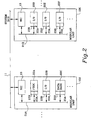
- FIG. 2 shows details of two modular units.
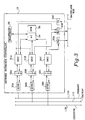
- FIG. 3 shows details of a network interface controller(NIC).
- FIG. 4 illustrates functional concentration achieved using the invention.
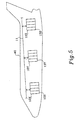
- FIG. 5 illustrates two types of functional separation using the invention.
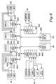
- FIG. 6 shows the preferred embodiment of the invention.
- Figure 1 is an overview of an aircraft control system 10 incorporating the invention. Shown in figure 1 are four system buses 11 and nine modular units(MUs). Modular units 12A-D are embodied as LRU or card cage type units and modular units 12E-I are embodied as being integrals parts of display heads.
- Side 1 primary bus 11A and side 2 primary bus 11B are coupled to all modular units 12.
- Backup buses 11C and 11D only communicate with MUs on their respective sides.
- Each MU includes a network interface controller(NIC) 13 which handles communicates between modules in the MU and the system buses 11.
- NICs 13 include a memory which stores a schedule defining the predetermined periodic and deterministic communication of data on the system buses 11. NICs 13 are described in further detail below.
- the NICs provide all communications on the system buses 11 to the modules in each MU. Because NICs provide such a common interface, it is understood that modules can be physically located in virtually any MUs attached to the system.
- FIG. 2 shows details of two modular units 12.
- Modular units 12J and 12K are coupled to a system bus 11 which also could be a redundant system bus.
- Each MU includes a NIC 13, a backplane bus 21, and several modules 22.
- NIC 13 provide the communications interface between system bus 11 and modules 22 as discussed elsewhere.
- Modules 22 are preferably divided by function into three types: processor modules, I/O modules, and data base modules. Dividing modules into such distinct types increases system flexibility.
- Processor modules typically include a microprocessor or similar computing device and support circuitry.
- Processor modules provide the "brains" of the system.
- I/O modules interface provide the "senses" and “muscle” for the system.
- I/O modules can be specific to aircraft functions or be designed for use by multiple functions. I/O modules interface with various aircraft systems, sensors, and utilities including autopilot servos, pressure sensors, inertial reference sensors, alternate buses such as ARINC 429, and the like.
- Aircraft utilities include such functions as air conditioning, electrical power, fire protection, fuel, hydraulic power, ice and rain protection, indication and recording, landing gear, lights, oxygen, pneumatic, water/waste, auxiliary power, doors, propellers, ignition, air, oil, thrust reversers, and starting.
- Each module has a common interface for interfacing between the functional portion(e.g. the processor circuitry, I/O circuitry, or data base circuitry) of the module and the NIC 13.
- the backplane interface 23 performs this function.
- Backplane interfaces 23 are standardized throughout the system to achieve flexibility and inter-changability.
- Backplane interfaces 23 include a transmitter portion 23A and a receiver portion 23B.
- the preferred embodiment uses shared memory or latch type devices to implement the transmitters 23A and receivers 23B.
- FIG. 3 shows details of a network interface controller(NIC) 13 suitable for use in the present invention.
- the NIC 13 is essentially a transceiver coupled to each system bus 11.
- three transceivers 30A-30C are coupled to a primary or onside bus 11A, a backup bus 11C, and a cross-side bus 11B respectively.
- Each transceiver 30 is capable of receiving signals on the associated system bus and of communicating these signals to the internal NIC components.
- each transceiver is also capable of receiving signals from the internal NIC components and transmitting these signals, or equivalents thereof, on the associated system bus.
- Each transceiver 11 communicates with a system network interface controller(SNIC) 31 via an isolation buffer 32.
- SNICs 31 are capable of exchanging digital data between a transceiver 30 and random access memories functioning as data buffers 33.
- Two receive buffers 33A and 33B and a single transmit buffer 33C are provided.
- Each buffer communicates with a backplane bus 21 which provides a communications link to the modules (not shown).
- Data stored in the receive may be made available to the modules by simulcasting or fanning out accumulated data across the backplane bus at predetermined time intervals.
- data stored in buffers 33A and 33B may be made available to the modules through a memory addressing scheme whereby each module intermittently polls each receiver buffer to determine if any received data is waiting.
- received data may be made available to the module by simulcasting or fanning out accumulated data across the backplane bus at predetermined time intervals.
- data that is to be transmitted by the NIC 13 on the system buses 11 is communicated across the MU internal backplane bus 21 to transmit buffer 33C.
- Data is placed in the transmit buffer 33C through either synchronous or asynchronous polling of backplane bus 21, or by data simulcast across the backplane bus 21 at regular or interrupt-driven intervals.
- a key component of the invention is microcontroller 34 which controls the operation of SNICs 31.
- the microcontroller 34 sequences data transmissions on each system bus 11 according to predetermined data schedules stored in memory 35.
- the stored schedule is adapted to each implementation of the invention with each module being allocated a fixed amount of bandwidth in a pre-determined sequence.
- Each module is guaranteed periodic access to the system buses 11 according to the stored schedule. Hence, communication across the system buses 11 is synchronous and deterministic. Because each NIC must respect the same timing sequence on the system buses, each NIC retains similar or identical schedules in memory. This system bus mechanism allows for improved reliability, since each module can anticipate and monitor the communications of all other participating modules. Moreover, each module is guaranteed periodic access to the system bus 11, thus insuring that critical messages are communicated without undue delay.
- a heartbeat monitor 36 monitors the operation of microcontroller 34. If a failure or power loss occurs, the heartbeat monitor 36 identifies the condition and takes appropriate actions such as disabling transmissions to prevent transmissions of corrupted data.
- NICs 13 may be found in the co-pending patent application entitled “Low Cost Redundant Communication System", filed on October 1, 1996, and assigned to the assignee of interest of this application.
- Figure 4 illustrates functional concentration achieved using the invention. This figure shows many functions combined or integrated into a single MU 12 inside of aircraft 40. Although applicant has discussed the advantages of physical separation of functions, the invention also supports unlimited functional concentration if it is desired. Therefore, if it is desired to concentrate several processing modules, I/O modules, and database modules in a single MU, the invention supports and simplifies this design.
- FIG. 4 Shown in figure 4 as part of MU 12 are power supply 41, processing modules 42, I/O modules 43, and database modules 44.
- FIG. 5 illustrates two types of functional separation using the invention.
- Aircraft 40 is shown with three physically separated MUs 13 which are each connected to system bus 11.
- One type of functional separation could be achieved by putting all the modules required for a function in the same MU.
- each MU 13 could include a processing module, an I/O module and a database module for implementing a particular function or set of functions.
- it could be desirable to separate the functional modules and concentrate the similar modules.
- all the processor modules would reside in MU 13X
- all the I/O modules would reside in MU 13Y
- all the database modules would reside in MU 13Z.
- FIG. 6 shows the preferred embodiment of the invention which incorporates many of the advantages discussed above.
- MUs 60 Shown in figure 6 arc eight MUs 60.
- An advantage of the invention is the flexibility to place modules in remote locations such as in display heads in an aircraft cockpit.
- MUs 60A-60D are integral parts of heads.
- the MU in each display head includes a processor module 61 and an I/O module 62.
- the I/O modules 62 receive data from aircraft sensors 63 which is processed by processing modules 61.
- Aircraft sensors include GPS sensors, air data sensors(ADM), inertial reference sensors(IMU), and the like.
- MUs 60E and 60F are shown with I/O cards interfacing with several aircraft systems 64. It should be noted that MUs 60E and 60F are shown having only one processing module even though several processor modules would normally be required to support the numerous I/O modules. However, the invention allows processing to be accomplished in any processing module in the system. For example, although engine I/O is shown in MU 60E, the processing of the I/O may be done in a display head such as MU 60C.
- MUs 60G and 60H which are an integral part of radio units 65.
Landscapes
- Engineering & Computer Science (AREA)
- Computer Networks & Wireless Communication (AREA)
- Signal Processing (AREA)
- Small-Scale Networks (AREA)
- Hardware Redundancy (AREA)
Claims (17)
- Flugzeugsteuersystem (10) zur Steuerung mehrerer Flugzeugfunktionen, wobei das Flugzeugsteuersystem (10) folgendes umfaßt:einen Systembus (11);mehrere Netzwerkschnittstellensteuerungen (13), die an den Systembus (11) angekoppelt sind, wobei sich jede der mehreren Netzwerkschnittstellensteuerungen (13) mit anderen Netzwerkschnittstellensteuerungen (13) synchronisieren und vordefinierte periodische und deterministische Daten über den Systembus (11) übertragen kann;mehrere Rückwandbusse (21), wobei an jede der mehreren Netzwerkschnittstellensteuerungen (13) einer der mehreren Rückwandbusse (21) angekoppelt ist, so daß die gesamten vordefinierten periodischen und deterministischen Daten über die mehreren Rückwandbusse (21) rundgesendet werden; undmehrere Module (22) mit einem Funktionsteil und einer Rückwandschnittstelle (23), wobei die Rückwandschnittstelle (23) mit einem der mehreren Rückwandbusse (21) gekoppelt ist und mit einer der mehreren Netzwerkschnittstellensteuerungen (13) kommuniziert, um Daten über den Systembus (11) zu senden und zu empfangen, wobei die Rückwandschnittstelle (23) einen Empfängerteil (23B), der auf die gesamten vordefinierten periodischen und deterministischen Daten, die auf dem Systembus (11) rundgesendet werden, zugreift, und einen Sendeteil (23A), der Zwischenmoduldaten aus dem Funktionsteil der einen der Netzwerkschnittstellensteuerungen (13) übermittelt, aufweist.
- Flugzeugsteuersystem (10) nach Anspruch 1, wobei jede der mehreren Netzwerkschnittstellensteuerungen (13) einen Speicher zum Speichern einer Beschreibung der vordefinierten periodischen und deterministischen Daten, die Zeitsteuerungs- und Folgeninformationen enthält, aufweist.
- Flugzeugsteuersystem (10) nach Anspruch 1, wobei die Kommunikation zwischen den mehreren Modulen (22) ungeachtet, welchen der mehreren Rückwandbusse (21) jedes der mehreren Module (22) zur Kommunikation verwendet, gleich ist.
- Flugzeugsteuersystem (10) nach Anspruch 1, wobei die mehreren Module (22) ein Verarbeitungsmodul (22A) und ein E/A-Modul (22B) enthalten, wobei das Verarbeitungsmodul (22A) an einen der mehreren Rückwandbusse (21) angekoppelt ist und mit dem E/A-Modul (22B) kommuniziert, das an einen anderen der mehreren Rückwandbusse (21) angekoppelt ist.
- Flugzeugsteuersystem (10) nach Anspruch 1, wobei die mehreren Module (22) ein Datenbankmodul (22C) enthalten.
- Flugzeugsteuersystem (10) nach Anspruch 1, weiterhin mit mindestens zwei Systembussen (11) und einem Busumschaltmittel (31), wobei das Busumschaltmittel (31) steuert, welcher der mindestens zwei Systembusse (11) den mehreren Rückwandbussen (21) die vordefinierten periodischen und deterministischen Daten zuführt.
- Flugzeugsteuersystem (10) nach Anspruch 6, wobei die mindestens zwei Systembusse (11) einen Crosside-Systembus (11B) enthalten, der die vordefinierten periodischen und deterministischen Daten auf einem der mehreren Rückwandbussen (21) rundsendet, der an eine der mehreren Netzwerkschnittstellensteuerungen (13) angekoppelt ist.
- Flugzeugsteuersystem (10) nach Anspruch 4, wobei das Verarbeitungsmodul (22A) der mehreren Module (22) physisch in einer ersten modularen (12) Einheit eines Anzeigekopfs angeordnet ist.
- Flugzeugsteuersystem (10) nach Anspruch 8, wobei das Verarbeitungsmodul (22A) der mehreren Module (22), das physisch in der ersten modularen Einheit (12) in dem Anzeigekopf angeordnet ist, Backup-Verarbeitungsfunktionen für ein anderes Verarbeitungsmodul der mehreren Module (22) bereitstellt, das physisch in einer zweiten modularen Einheit (12) angeordnet ist, die physisch von der ersten modularen Einheit (12) getrennt ist.
- Flugzeugsteuersystem (10) nach Anspruch 4, wobei das Verarbeitungsmodul (22A) der mehreren Module (22) die Verarbeitung für eine Flugzeughilfsfunktion bereitstellt.
- Flugzeugsteuersystem (10) nach Anspruch 6, wobei die Rückwandschnittstelle (23) ein Speicher ist, der gemeinsam von dem Funktionsteil und der einen der mehreren Netzwerkschnittstellensteuerungen (13) benutzt wird.
- Flugzeugsteuersystem (10) nach Anspruch 5, wobei das E/A-Modul (22B) und das Verarbeitungsmodul (22A) physisch in einem Anzeigekopf angeordnet sind und das E/A-Modul (22B) unverarbeitete Trägheitsbezugsdaten empfängt, die von dem Verarbeitungsmodul (22A) interpretiert werden.
- Flugzeugsteuersystem (10) nach Anspruch 1, umfassend:mindestens zwei modulare Einheiten (12), wobei jede der modularen Einheiten (12) folgendes aufweist:eine Netzwerkschnittstellensteuerung (13), die sich mit anderen Netzwerkschnittstellensteuerungen (13) synchronisieren und über den Systembus (11) vordefinierte periodische und deterministische Daten senden und empfangen kann, undein Modul (22), wobei das Modul (22) eine Rückwandschnittstelle (23) aufweist, die mit den Netzwerkschnittstellensteuerungen (13) kommuniziert, wobei die Rückwandschnittstelle (23) Daten so senden und empfangen kann, daß alle Übermittlungen der mindestens zwei modularen Einheiten (12) über den Systembus (11) rundgesendet werden.
- Verfahren zur Steuerung mehrerer Flugzeugsysteme mit den folgenden Schritten:(a) Bereitstellen eines virtuellen Rückwandnetzwerks, wobei das virtuelle Rückwandnetzwerk einen Systembus (11) und mindestens zwei Netzwerkschnittstellensteuerungen (13) enthält, die sich mit anderen Netzwerkschnittstellensteuerungen (13) synchronisieren und auf dem Systembus (11) vordefinierte periodische Daten senden und empfangen können; undBereitstellen mehrerer Rückwandbusse (21), wobei an jede der mehreren Netzwerkschnittstellensteuerungen (13) einer der mehreren Rückwandbusse (21) angekoppelt ist, so daß die gesamten vordefinierten periodischen und deterministischen Daten über die mehreren Rückwandbusse (21) rundgesendet werden; undBereitstellen mehrerer Module (22) mit einem Funktionsteil und einer Rückwandschnittstelle (23), wobei die Rückwandschnittstelle (23) mit einem der mehreren Rückwandbusse (21) gekoppelt ist und mit einer der mehreren Netzwerkschnittstellensteuerungen (13) kommuniziert, um Daten über den Systembus (11) zu senden und zu empfangen, wobei die Rückwandschnittstelle (23) einen Empfängerteil (23B), der auf die gesamten vordefinierten periodischen und deterministischen Daten, die auf dem Systembus (11) rundgesendet werden, zugreift, und einen Sendeteil (23A), der Zwischenmoduldaten aus dem Funktionsteil der einen der Netzwerkschnittstellensteuerungen (13) übermittelt, aufweist.
- Verfahren nach Anspruch 14, wobei mindestens eines der mehreren Module (22) ein Verarbeitungsmodul (22A) ist, wobei das Verarbeitungsmodul (22A) mit den mindestens zwei Netzwerkschnittstellensteuerungen (13) kommuniziert und eine redundante Funktionalität aufweist.
- Verfahren nach Anspruch 14, wobei mindestens eines der mehreren Module (22) ein fernes E/A-Modul (22B) ist, das physisch in der Nähe einer Flugzeugsystemeinheit angeordnet ist, mit der das E/A-Modul (22B) kommuniziert, wodurch die Länge der Kommunikationsleitung zwischen dem E/A-Modul (22B) und der Flugzeugsystemeinheit vermindert wird.
- Verfahren nach Anspruch 16, wobei ein Verarbeitungsmodul (22A) funktionsmäßig dem fernen E/A-Modul (22B) zugeordnet ist, aber physisch von dem fernen E/A-Modul (22B) getrennt ist und dennoch über den Systembus (11) mit dem fernen E/A-Modul (22B) kommunziert.
Applications Claiming Priority (3)
| Application Number | Priority Date | Filing Date | Title |
|---|---|---|---|
| US08724331 US5778203B1 (en) | 1996-10-01 | 1996-10-01 | Aircraft display and control system with virtual backplane architecture |
| US724331 | 1996-10-01 | ||
| PCT/US1997/017349 WO1998015087A1 (en) | 1996-10-01 | 1997-09-26 | Aircraft display and control system with virtual backplane architecture |
Publications (2)
| Publication Number | Publication Date |
|---|---|
| EP0931399A1 EP0931399A1 (de) | 1999-07-28 |
| EP0931399B1 true EP0931399B1 (de) | 2001-07-18 |
Family
ID=24910008
Family Applications (1)
| Application Number | Title | Priority Date | Filing Date |
|---|---|---|---|
| EP97945309A Expired - Lifetime EP0931399B1 (de) | 1996-10-01 | 1997-09-26 | Anzeige und steuerungssystem für flugzeug mit virtueller rückwandleiterplattenarchitektur |
Country Status (4)
| Country | Link |
|---|---|
| US (1) | US5778203B1 (de) |
| EP (1) | EP0931399B1 (de) |
| DE (1) | DE69705732T2 (de) |
| WO (1) | WO1998015087A1 (de) |
Families Citing this family (30)
| Publication number | Priority date | Publication date | Assignee | Title |
|---|---|---|---|---|
| DE19529434B4 (de) * | 1995-08-10 | 2009-09-17 | Continental Teves Ag & Co. Ohg | Microprozessorsystem für sicherheitskritische Regelungen |
| US5798458A (en) * | 1996-10-11 | 1998-08-25 | Raytheon Ti Systems, Inc. | Acoustic catastrophic event detection and data capture and retrieval system for aircraft |
| US6393343B1 (en) | 1997-03-13 | 2002-05-21 | Airbus Deutschland Gmbh | Passenger service unit and an aircraft cabin systems control with such service units |
| FR2778765B1 (fr) * | 1998-05-18 | 2001-10-05 | Eurocopter France | Systeme de surveillance du fonctionnement d'un aeronef, notamment d'un helicoptere |
| US6351786B2 (en) | 1998-08-24 | 2002-02-26 | Racal Instr Inc | VXI backplane system improvements and methods |
| US7206877B1 (en) * | 1998-12-22 | 2007-04-17 | Honeywell International Inc. | Fault tolerant data communication network |
| GB2364867B (en) | 2000-07-17 | 2003-12-10 | Advanced Risc Mach Ltd | A data processing apparatus and slave interface mechanism for controlling access to a slave logic unit by a plurality of master logic units |
| US7002961B1 (en) | 2000-10-16 | 2006-02-21 | Storage Technology Corporation | Information network virtual backplane |
| US20030152145A1 (en) * | 2001-11-15 | 2003-08-14 | Kevin Kawakita | Crash prevention recorder (CPR)/video-flight data recorder (V-FDR)/cockpit-cabin voice recorder for light aircraft with an add-on option for large commercial jets |
| US6801769B1 (en) | 2003-03-12 | 2004-10-05 | The Boeing Company | Modular aircraft information network system and an associated method of packaging the same |
| DE10325258B4 (de) * | 2003-06-03 | 2008-08-21 | Diehl Aerospace Gmbh | Luftfahrzeugkabinengerätesteuerung |
| US6967830B2 (en) * | 2003-08-26 | 2005-11-22 | The Boeing Company | Expansion module and network for avionic devices |
| JP2007527162A (ja) * | 2004-02-17 | 2007-09-20 | タレス アビオニクス インコーポレイテッド | インターネット・プロトコル(ip)順序付けを利用して乗客フライト情報システム(pfis)のコンポーネントを識別するシステムおよび方法 |
| US7421526B2 (en) * | 2005-08-24 | 2008-09-02 | Honeywell International Inc. | Reconfigurable virtual backplane architecture |
| US7756145B2 (en) * | 2005-12-02 | 2010-07-13 | The Boeing Company | Methods and apparatus providing an airborne e-enabled architecture as a system of systems |
| FR2899050B1 (fr) * | 2006-03-21 | 2008-09-19 | Airbus France Sas | Procede de communication de donnees entre des sytemes de traitement heterogenes connectes en reseau local et systeme de communication mettant en oeuvre ce procede |
| US20080037989A1 (en) * | 2006-08-14 | 2008-02-14 | Paul Douglas Stoner | Method And Apparatus For Handling Data And Aircraft Employing Same |
| US20080089087A1 (en) * | 2006-10-16 | 2008-04-17 | Paul Douglas Stoner | Apparatus and Method Pertaining to Light-Based Power Distribution in a Vehicle |
| US20080154444A1 (en) * | 2006-12-22 | 2008-06-26 | Boeing Company A Corporation Of Delaware | Apparatus and method for cooperative employment with installed airborne application control system |
| US8645148B2 (en) * | 2006-12-29 | 2014-02-04 | The Boeing Company | Methods and apparatus providing an E-enabled ground architecture |
| FR2945647A1 (fr) * | 2009-05-18 | 2010-11-19 | Airbus France | Methode d'optimisation d'une plateforme avionique |
| JP5607919B2 (ja) * | 2009-12-16 | 2014-10-15 | 川崎重工業株式会社 | 統合型航空機搭載電子システム |
| US8275494B1 (en) | 2009-12-31 | 2012-09-25 | Michael Roth | System, apparatus and method for controlling an aircraft |
| US9137038B1 (en) * | 2012-08-30 | 2015-09-15 | Rockwell Collins, Inc. | Integrated modular avionics system with distributed processing |
| US20160217095A1 (en) * | 2015-01-22 | 2016-07-28 | Hamilton Sundstrand Corporation | Modular signal interface unit |
| US10831947B1 (en) | 2017-06-09 | 2020-11-10 | Rockwell Collins, Inc. | System and method for optimizing design of aircraft backplane spatial separation |
| RU2667040C1 (ru) * | 2017-09-05 | 2018-09-13 | Публичное акционерное общество "ОАК - центр комплексирования" | Интегрированная вычислительная система самолета МС-21 |
| US11175937B2 (en) | 2018-03-30 | 2021-11-16 | The Boeing Company | Virtualized avionics systems for operational environments |
| US12579344B2 (en) * | 2020-09-15 | 2026-03-17 | The Boeing Company | Hosting pre-certified systems, remote activation of customer options, and optimization of flight algorithms in an emulated environment with real world operational conditions and data |
| US12012218B2 (en) * | 2021-11-08 | 2024-06-18 | Rockwell Collins, Inc. | Embedded display automatic flight controls distributed architecture |
Family Cites Families (3)
| Publication number | Priority date | Publication date | Assignee | Title |
|---|---|---|---|---|
| US5544329A (en) * | 1992-07-31 | 1996-08-06 | Grumman Aerospace Corporation | Interface system with memory map locations for holding flags indicating a priority for executing instructions held within messages received by the interface |
| US5412651A (en) * | 1993-02-11 | 1995-05-02 | Nec America, Inc. | Structure and method for combining PCM and common control data on a backplane bus |
| US5426774A (en) * | 1993-04-06 | 1995-06-20 | Honeywell Inc. | Method for maintaining a sequence of events function during failover in a redundant multiple layer system |
-
1996
- 1996-10-01 US US08724331 patent/US5778203B1/en not_active Expired - Lifetime
-
1997
- 1997-09-26 EP EP97945309A patent/EP0931399B1/de not_active Expired - Lifetime
- 1997-09-26 WO PCT/US1997/017349 patent/WO1998015087A1/en not_active Ceased
- 1997-09-26 DE DE69705732T patent/DE69705732T2/de not_active Expired - Lifetime
Also Published As
| Publication number | Publication date |
|---|---|
| WO1998015087A1 (en) | 1998-04-09 |
| EP0931399A1 (de) | 1999-07-28 |
| US5778203A (en) | 1998-07-07 |
| US5778203B1 (en) | 2000-02-08 |
| DE69705732D1 (de) | 2001-08-23 |
| DE69705732T2 (de) | 2002-05-23 |
Similar Documents
| Publication | Publication Date | Title |
|---|---|---|
| EP0931399B1 (de) | Anzeige und steuerungssystem für flugzeug mit virtueller rückwandleiterplattenarchitektur | |
| EP0754991B1 (de) | Fehlertolerantes verteiltes Steuerungssystem | |
| US4845495A (en) | Integrated avionics control and display arrangement | |
| US6801769B1 (en) | Modular aircraft information network system and an associated method of packaging the same | |
| US8151024B2 (en) | Reconfigurable virtual backplane systems and methods | |
| CN101604162B (zh) | 一种民机航电综合模块化核心处理系统 | |
| US4788531A (en) | Automatic fault reporting system | |
| US10230574B2 (en) | Avionics calculator with integrated routing module, related communication network and communication installation, and aircraft comprising such a communication installation | |
| US8255095B2 (en) | Modular avionics system of an aircraft | |
| WO2004003696A2 (en) | Aircraft communication distribution system | |
| US20100289963A1 (en) | Display Device for Aircraft Cockpit and Method for Managing a Video Data Network | |
| EP2394417B1 (de) | Flugzeugcockpit hybridensteuerungspanel | |
| ATE287822T1 (de) | Flugsteuerungsmodule, eingebaut in die integrierte modulare avionik | |
| WO1985002281A1 (en) | Automatic fault reporting system | |
| US5408616A (en) | System for redirecting output to either return bus or next module line upon the detection of the presence or absence of next module using ground line | |
| Morgan | Integrated modular avionics for next generation commercial airplanes | |
| US7206877B1 (en) | Fault tolerant data communication network | |
| Paulitsch et al. | Industrial applications | |
| CN111679927A (zh) | 一种余度重构的容错计算机 | |
| US7421526B2 (en) | Reconfigurable virtual backplane architecture | |
| US10270887B2 (en) | Server system, aircraft or spacecraft and method | |
| Franz et al. | A Space Wire/SpaceFibre architecture based on ADHA | |
| US20250229911A1 (en) | Offboard graphics rendering gateway via avionics full duplex ethernet for a cockpit display system | |
| CN115412155B (zh) | 一种星载大带宽弹性异构资源数据处理系统的母板 | |
| Hoyme et al. | SAFEbus (for avionics) |
Legal Events
| Date | Code | Title | Description |
|---|---|---|---|
| PUAI | Public reference made under article 153(3) epc to a published international application that has entered the european phase |
Free format text: ORIGINAL CODE: 0009012 |
|
| 17P | Request for examination filed |
Effective date: 19990406 |
|
| AK | Designated contracting states |
Kind code of ref document: A1 Designated state(s): DE FR GB IT |
|
| 17Q | First examination report despatched |
Effective date: 20000427 |
|
| GRAG | Despatch of communication of intention to grant |
Free format text: ORIGINAL CODE: EPIDOS AGRA |
|
| GRAG | Despatch of communication of intention to grant |
Free format text: ORIGINAL CODE: EPIDOS AGRA |
|
| GRAH | Despatch of communication of intention to grant a patent |
Free format text: ORIGINAL CODE: EPIDOS IGRA |
|
| GRAH | Despatch of communication of intention to grant a patent |
Free format text: ORIGINAL CODE: EPIDOS IGRA |
|
| GRAA | (expected) grant |
Free format text: ORIGINAL CODE: 0009210 |
|
| AK | Designated contracting states |
Kind code of ref document: B1 Designated state(s): DE FR GB IT |
|
| REF | Corresponds to: |
Ref document number: 69705732 Country of ref document: DE Date of ref document: 20010823 |
|
| ITF | It: translation for a ep patent filed | ||
| ET | Fr: translation filed | ||
| REG | Reference to a national code |
Ref country code: GB Ref legal event code: IF02 |
|
| PLBE | No opposition filed within time limit |
Free format text: ORIGINAL CODE: 0009261 |
|
| STAA | Information on the status of an ep patent application or granted ep patent |
Free format text: STATUS: NO OPPOSITION FILED WITHIN TIME LIMIT |
|
| 26N | No opposition filed | ||
| PG25 | Lapsed in a contracting state [announced via postgrant information from national office to epo] |
Ref country code: IT Free format text: LAPSE BECAUSE OF NON-PAYMENT OF DUE FEES;WARNING: LAPSES OF ITALIAN PATENTS WITH EFFECTIVE DATE BEFORE 2007 MAY HAVE OCCURRED AT ANY TIME BEFORE 2007. THE CORRECT EFFECTIVE DATE MAY BE DIFFERENT FROM THE ONE RECORDED. Effective date: 20050926 |
|
| PGFP | Annual fee paid to national office [announced via postgrant information from national office to epo] |
Ref country code: GB Payment date: 20080808 Year of fee payment: 12 |
|
| PGFP | Annual fee paid to national office [announced via postgrant information from national office to epo] |
Ref country code: DE Payment date: 20090930 Year of fee payment: 13 |
|
| GBPC | Gb: european patent ceased through non-payment of renewal fee |
Effective date: 20090926 |
|
| PG25 | Lapsed in a contracting state [announced via postgrant information from national office to epo] |
Ref country code: GB Free format text: LAPSE BECAUSE OF NON-PAYMENT OF DUE FEES Effective date: 20090926 |
|
| REG | Reference to a national code |
Ref country code: FR Ref legal event code: ST Effective date: 20110531 |
|
| REG | Reference to a national code |
Ref country code: DE Ref legal event code: R119 Ref document number: 69705732 Country of ref document: DE Effective date: 20110401 |
|
| PG25 | Lapsed in a contracting state [announced via postgrant information from national office to epo] |
Ref country code: DE Free format text: LAPSE BECAUSE OF NON-PAYMENT OF DUE FEES Effective date: 20110401 Ref country code: FR Free format text: LAPSE BECAUSE OF NON-PAYMENT OF DUE FEES Effective date: 20100930 |
|
| PGFP | Annual fee paid to national office [announced via postgrant information from national office to epo] |
Ref country code: FR Payment date: 20090916 Year of fee payment: 13 |
|
| P01 | Opt-out of the competence of the unified patent court (upc) registered |
Effective date: 20230525 |