EP0930695A2 - Filter arrangement for converter with regulated voltage intermediate circuit and sinusoidal phase currents - Google Patents
Filter arrangement for converter with regulated voltage intermediate circuit and sinusoidal phase currents Download PDFInfo
- Publication number
- EP0930695A2 EP0930695A2 EP98124563A EP98124563A EP0930695A2 EP 0930695 A2 EP0930695 A2 EP 0930695A2 EP 98124563 A EP98124563 A EP 98124563A EP 98124563 A EP98124563 A EP 98124563A EP 0930695 A2 EP0930695 A2 EP 0930695A2
- Authority
- EP
- European Patent Office
- Prior art keywords
- filter
- filter arrangement
- converter
- damping
- star
- Prior art date
- Legal status (The legal status is an assumption and is not a legal conclusion. Google has not performed a legal analysis and makes no representation as to the accuracy of the status listed.)
- Granted
Links
Images


Classifications
-
- H—ELECTRICITY
- H02—GENERATION; CONVERSION OR DISTRIBUTION OF ELECTRIC POWER
- H02M—APPARATUS FOR CONVERSION BETWEEN AC AND AC, BETWEEN AC AND DC, OR BETWEEN DC AND DC, AND FOR USE WITH MAINS OR SIMILAR POWER SUPPLY SYSTEMS; CONVERSION OF DC OR AC INPUT POWER INTO SURGE OUTPUT POWER; CONTROL OR REGULATION THEREOF
- H02M1/00—Details of apparatus for conversion
- H02M1/12—Arrangements for reducing harmonics from ac input or output
-
- H—ELECTRICITY
- H02—GENERATION; CONVERSION OR DISTRIBUTION OF ELECTRIC POWER
- H02H—EMERGENCY PROTECTIVE CIRCUIT ARRANGEMENTS
- H02H9/00—Emergency protective circuit arrangements for limiting excess current or voltage without disconnection
- H02H9/005—Emergency protective circuit arrangements for limiting excess current or voltage without disconnection avoiding undesired transient conditions
Abstract
Description
Die Erfindung betrifft eine Filteranordnung zur Dämpfung von leitungsgebundenen nieder- und hochfrequenten Netzrückwirkungen, insbesondere zur selektiven Dämpfung im Frequenzbereich von 2kHz bis 150kHz, für Umrichter mit geregeltem Spannungszwischenkreis und sinusförmigen Phasenströmen, welche zwischen Netzausgang (Line) und Eingang (Load) des Umrichters angeordnet ist.The invention relates to a filter arrangement for damping wired low and high frequency network perturbations, especially for selective attenuation in the frequency domain from 2kHz to 150kHz, for converters with regulated voltage intermediate circuit and sinusoidal phase currents, which between Line output and input (load) of the converter is arranged.
Beim Betrieb eines Umrichters mit Spannungszwischenkreis sind
Netzrückwirkungen (Leitungsgebundene Störaussendung) unvermeidbar.
Das Spektrum der Störaussendung kann dabei in vier
Frequenzbereiche untergliedert werden:
Für den 4. Frequenzbereich gibt es verbindliche Grenzwerte (Grenzwertklasse A / B) die im Rahmen der CE-Konformitätserklärung im Hinblick auf Elektromagnetische Verträglichkeit EMV eingehalten werden müssen. Grenzwerte für den 2. Frequenzbereich sind derzeit bereits in Planung.There are binding limit values for the 4th frequency range (Limit value class A / B) as part of the CE declaration of conformity with regard to electromagnetic compatibility EMC must be observed. Limit values for the 2nd frequency range are currently being planned.
Die Forderungen der Elektrizitätswerke insbesondere des VDEW (Verein Deutscher Elektrizitätswerke) bezüglich der Verbesserung des Leistungsfaktors betreffen den 1. Frequenzbereich und können mit einer Drehstrombrückenschaltung wie der herkömmlichen B6-Brücke nicht erfüllt werden (vgl. Brosch: Moderne Stromrichterantriebe, 1. Auf1., Würzburg, Vogel-Verlag 1989, S. 91f). Zur Erfüllung dieser Anforderungen ist ein Umrichter mit sinusförmiger Stromaufnahme erforderlich.The demands of the electricity companies, in particular the VDEW (Association of German Electricity Works) regarding the improvement of the power factor concern the 1st frequency range and can be used with a three-phase bridge circuit like the conventional one B6 bridge cannot be met (see broschure: Moderne Power converter drives, 1. Auf1., Würzburg, Vogel-Verlag 1989, pp. 91f). A converter is required to meet these requirements with sinusoidal current consumption required.
Das Spektrum der Störungen wird damit in den 2. bzw. 3. Frequenzbereich verlagert. Ein Vorteil dabei ist, daß in diesem Frequenzbereich die Störungen mit vertretbarem Aufwand herausgefiltert werden können.The spectrum of interference is thus in the 2nd or 3rd frequency range shifted. One advantage is that in this Frequency range the interference filtered out with reasonable effort can be.
Für den Betrieb eines Umrichters mit geregeltem Spannungszwischenkreis sind der 2. bzw. 3. Frequenzbereich jedoch auch ohne Berücksichtigung irgendwelcher Grenzwerte von entscheidender Bedeutung. Die Störaussendung ist in diesem Frequenzbereich sehr hoch und kann von Lärmbelästigung bis hin zur Störung anderer an diesem Netz betriebener Geräte führen.For the operation of an inverter with a regulated voltage intermediate circuit are the 2nd and 3rd frequency range, however without taking any critical limits into account Meaning. The interference emission is in this frequency range very high and can range from noise pollution to Failure of other devices operated on this network.
Herkömmliche Netzfilter sind für den 4. Frequenzbereich und den Betrieb von Umrichtern mit B6-Brückenschaltung (ungeregeltem Spannungszwischenkreis) entwickelt. Die Frequenzbereiche darunter blieben dabei jedoch unberücksichtigt.Conventional line filters are for the 4th frequency range and the operation of inverters with B6 bridge circuit (uncontrolled Voltage intermediate circuit) developed. The frequency ranges however, this was not taken into account.
Beim Betrieb von Umrichtern mit geregeltem Spannungszwischenkreis an einem solchen Filter können Resonanzen zur Überhöhung der Störaussendung und damit zur Verschärfung der geschilderten Probleme führen.When operating inverters with a regulated DC link Such a filter can cause resonances to increase the emission of interference and thus to tighten the described Cause problems.
Aufgabe der vorliegenden Erfindung ist es daher, eine Filteranordnung für den 2. und 3. der eingangs angeführten Frequenzbereiche zu schaffen.The object of the present invention is therefore a filter arrangement for the 2nd and 3rd of the frequency ranges mentioned at the beginning to accomplish.
Diese Aufgabe wird gemäß der vorliegenden Erfindung durch eine Weiterbildung der eingangs genannten Filteranordnung gelöst, indem ein symmetrischer Filterteil bestehend aus je einem jeder Netzphase zugeordneten Kondensator zur Verringerung der Amplitude der Störspannung vorgesehen ist, dem eine Parallelschaltung aus einem Dämpfungswiderstand zum Bedämpfen der Resonanzfrequenz und einer Induktivität für die Netzfrequenz-Umladeströme nachgeschaltet ist, sowie mit einem asymmetrischen Filterteil bestehend aus den symmetrischen Filtermitteln in Sternschaltung nachgeschalteten weiteren Kondensatoren, deren Sternpunkt über eine weitere Parallelschaltung aus einem Kondensator und einem Dämpfungswiderstand mit der Netzerde verbunden ist.This object is achieved according to the present invention by a Further development of the filter arrangement mentioned in the introduction, by a symmetrical filter part consisting of one capacitor to reduce each grid phase the amplitude of the interference voltage is provided, a parallel connection from a damping resistor for damping the resonance frequency and an inductance for the mains frequency recharge currents is connected downstream, as well as with an asymmetrical Filter part consisting of the symmetrical filter media further capacitors connected in star connection, their star point via another parallel connection from a capacitor and a damping resistor with the Network earth is connected.
Um bei rückspeisefähigen Umrichtern ungedämpfte Schwingungen zwischen der Eingangs- und Ausgangsseite des Umrichters zu vermeiden, weist eine erste vorteilhafte Ausgestaltung der Filteranordnung gemäß der vorliegenden Erfindung umrichterseitig in einer weiteren Filterstufe weitere Kondensatoren auf, die in Sternschaltung zwischen die Netzphasen geschaltet sind und deren Sternpunkt über einen Dämpfungswiderstand mit der Netzerde verbunden ist.For undamped vibrations in regenerative converters between the input and output sides of the converter avoid, has a first advantageous embodiment of the Filter arrangement according to the present invention on the converter side further capacitors in a further filter stage on, which are connected in a star connection between the mains phases are and their star point with a damping resistor the network earth is connected.
Eine alternative vorteilhafte Ausgestaltung der Filteranordnung gemäß der vorliegenden Erfindung weist umrichterseitig in einer weiteren Filterstufe für jede Phase eine Induktivität auf, welche über einen gemeinsamen Kern verfügen und eine weitere Wicklung zur Einkopplung eines Dämpfungswiderstands aufweisen.An alternative advantageous embodiment of the filter arrangement According to the present invention, the converter side an inductance for each phase in a further filter stage which have a common core and a further winding for coupling a damping resistor exhibit.
Zu einer optimalen Vermeidung einer Resonanzüberhöhung asymmetrischer
Ströme ist eine weitere vorteilhafte Ausgestaltung
der Filteranordnung gemäß der vorliegenden Erfindung dadurch
gekennzeichnet, daß der Dämpfungswiderstand des asymmetrischen
Filterteils einen Wert
Eine weitere vorteilhafte Ausgestaltung der Filteranordnung gemäß der vorliegenden Erfindung weist einen als PTC-Widerstand ausgestalteten Dämpfungswiderstand des asymmetrischen Filterteils auf.Another advantageous embodiment of the filter arrangement according to the present invention has one as a PTC resistor designed damping resistance of the asymmetrical Filter part on.
Beispielsweise für den Fall, daß das Filter versehentlich an einem IT-Netz betrieben wird, besitzt dieser Aufbau folgenden Vorteil: bei einem Schluß zwischen Phase und Erde wird dieser PTC-Widerstand (positiver Temperaturkoeffizient) hochohmig. Dieser Prozess ist reversibel - das Netzfilter wird nicht zerstört.For example, in the event that the filter accidentally turns on is operated in an IT network, this structure has the following Advantage: if there is a connection between phase and earth, this becomes PTC resistor (positive temperature coefficient) high resistance. This process is reversible - the line filter will not destroyed.
Besonders vorteilhaft läßt sich das Prinzip der Erfindung auch auf Filteranordnungen übertragen, die durch Stern-Dreieck-Transformation oder Dreieck-Stern-Transformation entstehen.The principle of the invention can be particularly advantageous also transferred to filter arrangements by star-delta transformation or triangle-star transformation.
Weitere Vorteile und erfinderische Einzelheiten werden anhand der folgenden Beschreibung eines Ausführungsbeispiels und in Verbindung mit den Figuren deutlich. es zeigen
- FIG 1
- Ersatzschaltbild für den symmetrischen Teil des Netzfilters,
- FIG 2
- Ersatzschaltbild für den asymmetrischen Teil des Netzfilters,
- FIG 3
- Erweiterung des aymmetrischen Anteils zur Bedämpfung des Schwingkreises C2 - Lk,a - Ca,
- FIG 4
- kostenoptimierte Alternative zur Filteranordnung nach FIG 3 und
- FIG 5
- komplettes Netzfilter gemäß der vorliegenden Erfindung.
- FIG. 1
- Equivalent circuit diagram for the symmetrical part of the line filter,
- FIG 2
- Equivalent circuit diagram for the asymmetrical part of the line filter,
- FIG 3
- Expansion of the asymmetrical part to dampen the resonant circuit C 2 - L k, a - Ca,
- FIG 4
- Cost-optimized alternative to the filter arrangement according to FIG. 3 and
- FIG 5
- complete line filter according to the present invention.
In der Darstellung nach FIG 1 ist ein Ersatzschaltbild für den symmetrischen Teil des Netzfilters gemäß der vorliegenden Erfindung gezeigt.1 is an equivalent circuit diagram for the symmetrical part of the line filter according to the present Invention shown.
Dieses besteht aus einem elektrischen Netz N, der Filteranordnung F und einem Umrichter U. Das Netz weist eine symmetrisch wirksame Netzinduktivität auf und der Umrichter U eine symmetrisch wirksame Kommutierungsdrossel. Die Filteranordnung F zeigt den symmetrischen Filterteil bestehend aus einer parallel zum Netzausgang bzw. zum Umrichtereingang geschalteten Serienschaltung aus einem Kondensator C1 und einer Parallelschaltung aus einer Induktivität L1 mit einem Dämpfungswiderstand R1.This consists of an electrical network N, the filter arrangement F and a converter U. The network has a symmetrical effective network inductance and the converter U a symmetrically effective commutation choke. The filter arrangement F shows the symmetrical filter part consisting of a connected in parallel to the mains output or the converter input Series connection of a capacitor C1 and a parallel connection from an inductance L1 with a damping resistor R1.
Dabei beschreibt Ln,s die symmetrisch wirksame Netzinduktivität und Lk,s die symmetrisch wirksame Induktivität der Kommutierungsdrossel.Ln, s describes the symmetrically effective network inductance and Lk, s the symmetrically effective inductance of the commutation choke.
Ohne den Einsatz eines Filters wird die Amplitude der Störungen
auf dem Netz durch den induktiven Spannungsteiler bestehend
aus Lk,s und Ln,s nach Folgender Berechnungsvorschrift
bestimmt:
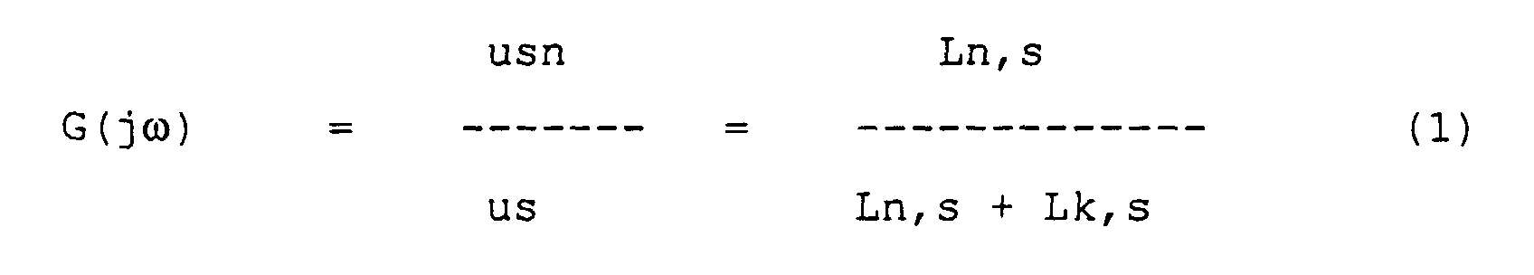
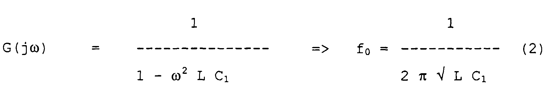
In einem ersten Schritt wird nun mit einem Kondensator C1 die
Amplitude der Störspannung auf einen gewünschten Wert verringert.
Die Übertragungsfunktion für diesen Fall lautet dann:
Dabei ist L gleich der Parallelschaltung von Ln,s und Lk,s.L is the parallel connection of Ln, s and Lk, s.
Wie man erkennt, kann die Resonanzfrequenz durch die Netzimpedanz in einem großen Bereich verschoben werden. Eine Einschränkung der Netzimpedanz würde diesen Bereich verringern, ist jedoch in der Realität nicht durchsetzbar. Es wird also immer Netzbedingungen geben, bei denen es zu einer Resonanzüberhöhung des Störspektrums kommt.As you can see, the resonance frequency can be determined by the network impedance be moved in a large area. A restriction the grid impedance would reduce this range, however, is not enforceable in reality. So it will there are always network conditions in which there is an excessive resonance of the interference spectrum comes.
Im nächsten Schritt wird daher diese Resonanzstelle mit dem Dämpfungswiderstand R1 bedämpft. Der Nachteil dabei ist die hohe Verlustleistung des Widerstandes aufgrund der 50Hz Grundschwingung der Netzspannung.In the next step, this resonance point with the Damping resistor R1 damped. The disadvantage is that high power loss of the resistor due to the 50Hz Basic oscillation of the mains voltage.
Die 50Hz - Umladeströme können daher von einer Drossel L1 übernommen werden. Diese erhöht dann auch gleichzeitig die Mindestimpedanz im Kreis ohne den Laststrom führen zu müssen. Es kann also eine relativ kleine und damit kostengünstige Drossel verwendet werden.The 50 Hz charge reversal currents can therefore from a choke L1 be taken over. This then also increases the Minimum impedance in the circuit without having to carry the load current. So it can be a relatively small and therefore inexpensive Choke can be used.
In der Darstellung nach FIG 2 ist ein Ersatzschaltbild für den asymmetrischen Teil des Netzfilters gezeigt.In the representation according to FIG 2 is an equivalent circuit diagram for shown the asymmetrical part of the line filter.
Auf der linken Seite ist wiederum ein elektrisches Netz H gezeigt, in diesem Fall anhand eines Dreiphasennetzes mit asymmetrisch wirksamen Netzinduktivitäten. Daran schließt sich der asymmetrische Teil der Filteranordnung F, auf die wiederum der bereits erwähnte Umrichter U folgt, welcher eine asymmetrisch wirksame parasitäre Kapazität am Umrichterausgang aufweist. Der asymmetrische Filterteil weist eingangsseitig und ausgangsseitig für jede Netzphase eine Induktivität auf, wobei die eingangsseitigen und ausgangsseitigen Netzinduktivitäten der einzelnen Netzphasen jeweils über einen gemeinsamen magnetischen Kern gekoppelt sind (stromkompensierte Drossel). Zwischen eingangsseitigen und ausgangsseitigen Induktivitäten des asymmetrischen Filterteils sind in Sternschaltung Kondensatoren C21, C22, C23 geschaltet, an deren Sternpunkt wiederum ein Parallelschaltung aus einer weiteren Kapazität C2 mit einem Dämpfungswiderstand R2 vorgesehen ist, worüber der Sternpunkt mit der Netzerde PE verbunden ist. An electrical network H is again shown on the left, in this case using a three-phase network with asymmetrical effective network inductances. That follows the asymmetrical part of the filter arrangement F, on which in turn the already mentioned converter U follows, which has an asymmetrical effective parasitic capacitance at the converter output having. The asymmetrical filter section faces the input and on the output side an inductance for each line phase, where the input-side and output-side network inductances of the individual network phases via a common one magnetic core are coupled (current-compensated choke). Between inductors on the input and output side of the asymmetrical filter part are in star connection Capacitors C21, C22, C23 connected at their neutral point again a parallel connection from another capacity C2 is provided with a damping resistor R2, about what the star point is connected to the PE earth.
Dabei ist Ln,a die asymmetrisch wirksame Netzinduktivität und Lk,a die asymmetrisch wirksame Induktivität der Kommutierungsdrossel. Ca beschreibt die asymmetrisch wirksame parasitäre Kapazität am Umrichterausgang (incl. Leitungskapazität).Ln, a is the asymmetrically effective network inductance and Lk, a the asymmetrically effective inductance of the commutation choke. Ca describes the asymmetrically effective parasitic Capacity at the converter output (incl. Line capacity).
Analog zum oben bereits erläuterten kann es auch hier ohne
einen Dämpfungswiderstand R2 zu einer Resonanzüberhöhung der
asymmetrischen Ströme kommen. Der Widerstand R2 kann nun so
gewählt werden, daß eine Resonanzüberhöhung gänzlich ausgeschlossen
wird (unabhängig von Ln,a):
Wenn diese Bedingung erfüllt ist, kann der asymmetrische Filterteil so dimensioniert werden, daß der Betrieb an einem FI-Schutzschalter möglich wird.If this condition is met, the asymmetrical filter part can be dimensioned so that operation on a residual current circuit breaker becomes possible.
Die Dämpfungseigenschaften des bisher beschriebenen Netzfilters würden bereits ausreichen, um den Anforderungen bzgl. Netzrückwirkungen zu genügen.The damping properties of the line filter described so far would already be sufficient to meet the requirements regarding Network perturbations are sufficient.
Mit dem erfindungsgemäßen Filterkonzept kann jedoch noch ein weiteres Problem gelöst werden: bei rückspeisefähigen Umrichtern kommt es zu ungedämpften Schwingungen zwischen der Eingangs- und der Ausgangsseite des Umrichters.With the filter concept according to the invention, however, one can Another problem can be solved: with regenerative converters undamped vibrations occur between the input and the output side of the converter.
Eine zur Lösung auch dieses Problems geeignete Filteranordnung zeigt die Darstellung in FIG 3 in Form einer Erweiterung des aymmetrischen Filterteils zur Bedämpfung des Schwingkreises C2 - L - Ca. A filter arrangement that is also suitable for solving this problem shows the representation in FIG 3 in the form of an extension of the asymmetrical filter part for damping the resonant circuit C2 - L - Approx.
Dabei sind den ausgangsseitigen Netzinduktivitäten des asymmetrischen Filterteils weitere Kondensatoren C31, C32, C33 in Sternschaltung nachgeschaltet, deren Sternpunkt über einen weiteren Dämpfungswiderstand R3 mit der Netzerde PE verbunden ist.The network inductances on the output side are asymmetrical Filter part further capacitors C31, C32, C33 in Star connection, the star point of which is connected via a additional damping resistor R3 connected to the network earth PE is.
Zusätzlich sind eingangsseitig in herkömmlicher Weise Kondensatoren C11, C12, C13 in Sternschaltung zwischen die Netzphasen geschaltet.In addition, capacitors are conventionally used on the input side C11, C12, C13 in star connection between the mains phases switched.
Die Resonanzfrequenz wird im wesentlichen bestimmt durch die parasitäre Kapazität des Umrichters (incl. der Motorleitungen) gegen Erde und die asymmetrisch wirksame Induktivität der Kommutierungsdrossel (incl. - falls vorhanden - der Induktivität der stromkompensierten Drossel auf der Umrichterseite des Filters).The resonance frequency is essentially determined by the parasitic capacitance of the converter (including the motor cables) against earth and the asymmetrically effective inductance the commutation choke (including - if present - the inductance the current-compensated choke on the converter side of the filter).
Um auch diese Schwingung zu bedämpfen, wird mit den Kondensatoren C31, C32, C33 (>> Ca) ein virtueller Sternpunkt geschaffen und über einen weiteren Dämpfungswiderstand R3 mit Erde PE verbunden.To dampen this vibration as well, use the capacitors C31, C32, C33 (>> Ca) created a virtual star point and with another damping resistor R3 Earth PE connected.
Die Darstellung nach FIG 4 zeigt eine kostenoptimierte Alternative zur in FIG 3 dargestellten Lösung.The illustration in FIG. 4 shows a cost-optimized alternative to the solution shown in FIG 3.
In dieser alternativen Ausführungsform ist der Dämpfungswiderstand R3, welcher bereits in der Darstellung gemäß FIG 3 eingeführt wurde, dadurch in den Kreis eingekoppelt, das die ausgangsseitige Induktivität erweitert wird, indem eine vierte Wicklung auf dem gemeinsamen magnetischen Kern vorgesehen ist, welche durch den Dämpfungswiderstand R3 kurzgeschlossen ist. In this alternative embodiment, the damping resistance is R3, which is already shown in FIG. 3 was introduced, thereby coupled into the circle that the output inductance is expanded by a fourth Winding provided on the common magnetic core which is short-circuited by the damping resistor R3 is.
Als Alternative kann zur Schwingungsbedämpfung somit über eine vierte Wicklung der Dämpfungswiderstand R3 in den Kreis eingekoppelt werden.As an alternative, vibration damping can be achieved via a fourth winding the damping resistor R3 in the circuit be coupled.
Die Darstellung gemäß FIG 5 zeigt ein Ausführungsbeispiel der Filteranordnung gemäß der vorliegenden Erfindung, in das die vorangehenden Ausführungen eingeflossen sind.5 shows an embodiment of the Filter arrangement according to the present invention, in which the previous statements have been incorporated.
Dabei ist der Eingang der Filteranordnung mit LIN und der Ausgang mit LOAD gekennzeichnet. In dieser kompletten Netzfilteranordnung befindet sich alle im vorangehenden beschriebenen Filtermittel wieder. So weist die Filteranordnung eingangsseitig in herkömmlicher Weise in Sternschaltung zwischen die Netzphasen geschaltete Kondensatoren C11, C12 und C13 auf. Es folgt die einangsseitige Netzinduktivität. Für jede einzelne Netzphase U, V, W ist je ein in der Darstellung gemäß FIG 1 gezeigter symmetrischer Filterteil bestehend - am Beispiel der Netzphase U - aus einem Kondensator C1u und einer Parallelschaltung aus einem Dämpfungswiderstand R1u und einer Induktivität L1u vorgesehen. Die anderen Netzphasen V und W besitzen entsprechende symmetrische Filterteile.The input of the filter arrangement with LIN and Output marked with LOAD. In this complete line filter arrangement is all described above Filter media again. So the filter arrangement has on the input side in a conventional manner in a star connection between the network phases switched capacitors C11, C12 and C13 on. The network inductance on the input side follows. For every individual network phase U, V, W is one in the representation according to 1 shown symmetrical filter part consisting - on Example of the line phase U - from a capacitor C1u and one Parallel connection from a damping resistor R1u and an inductor L1u is provided. The other network phases V and W have corresponding symmetrical filter parts.
Während ein solcher symmetrischer Filterteil für die Phase W zwischen die Phasen U und W geschaltet ist, sind die entsprechenden symmetrischen Filterteile der Phasen U und V mit den Kondensatoren C22 und C23 der Sternschaltung von Kondensatoren C21 bis C23 des asymmetrischen Filterteiles verbunden. Der Kondensator C21 dieses asymmetrischen Filterteiles ist hingegen direkt zur Phase U geführt. Der Sternpunkt der Kondensatoren C21 bis C23 ist dann in der weiter oben beschriebenen Art und Weise über eine Parallelschaltung aus einem weiteren Kondensator C2 und einem Dämpfungswiderstand R2 mit der Netzerde PE verbunden. Der weitere Dämpfungswiderstand R3 ist in der in der Darstellung gemäß FIG 4 gezeigten Art und Weise über eine vierte Wicklung in den Kreis eingekoppelt. While such a symmetrical filter part for phase W is switched between the phases U and W, are the corresponding symmetrical filter parts of the phases U and V with the Capacitors C22 and C23 of the star connection of capacitors C21 to C23 of the asymmetrical filter part connected. The capacitor C21 of this asymmetrical filter part is however led directly to phase U. The star point of the capacitors C21 to C23 is then that described above Way of parallel connection from one another capacitor C2 and a damping resistor R2 with the network earth PE connected. The further damping resistor R3 is in the manner shown in the illustration of FIG 4 and Coupled into the circle via a fourth winding.
Auf diese Weise erhält man eine Filteranordnung bestehend aus symmetrischem Filterteil und asymmetrischem Filterteil, mit der die im vorangehenden beschriebenen Vorteile der vorliegenden Erfindung erreicht werden können.In this way you get a filter arrangement consisting of symmetrical filter part and asymmetrical filter part, with of the advantages of the present described above Invention can be achieved.
Claims (6)
Applications Claiming Priority (2)
| Application Number | Priority Date | Filing Date | Title |
|---|---|---|---|
| DE29800567U | 1998-01-14 | ||
| DE29800567U DE29800567U1 (en) | 1998-01-14 | 1998-01-14 | Damping filter arrangement for converters with regulated voltage intermediate circuit and sinusoidal phase currents |
Publications (3)
| Publication Number | Publication Date |
|---|---|
| EP0930695A2 true EP0930695A2 (en) | 1999-07-21 |
| EP0930695A3 EP0930695A3 (en) | 2000-04-05 |
| EP0930695B1 EP0930695B1 (en) | 2008-09-10 |
Family
ID=8051264
Family Applications (1)
| Application Number | Title | Priority Date | Filing Date |
|---|---|---|---|
| EP98124563A Revoked EP0930695B1 (en) | 1998-01-14 | 1998-12-22 | Filter arrangement for converter with regulated voltage intermediate circuit and sinusoidal phase currents |
Country Status (4)
| Country | Link |
|---|---|
| US (1) | US6075425A (en) |
| EP (1) | EP0930695B1 (en) |
| AT (1) | ATE408260T1 (en) |
| DE (2) | DE29800567U1 (en) |
Cited By (4)
| Publication number | Priority date | Publication date | Assignee | Title |
|---|---|---|---|---|
| WO2003105328A1 (en) * | 2002-06-07 | 2003-12-18 | Epcos Ag | Current-compensated choke and circuit arrangement comprising the current-compensated choke |
| US6690250B2 (en) | 2000-12-07 | 2004-02-10 | Danfoss Drives A/S | RFI filter for a frequency converter |
| US7050278B2 (en) | 2002-05-22 | 2006-05-23 | Danfoss Drives A/S | Motor controller incorporating an electronic circuit for protection against inrush currents |
| EP3934047A1 (en) * | 2020-06-30 | 2022-01-05 | Siemens Aktiengesellschaft | Filter device and method for operating the filter device |
Families Citing this family (29)
| Publication number | Priority date | Publication date | Assignee | Title |
|---|---|---|---|---|
| DE19814059A1 (en) * | 1998-03-30 | 1999-10-07 | Asea Brown Boveri | Load-side filter arrangement for a converter circuit arrangement |
| BR0011157A (en) * | 1999-04-09 | 2002-02-26 | Ontario Inc 1061933 | Harmonic attenuation device and method of reducing a voltage drop |
| DE10034054A1 (en) * | 2000-07-13 | 2002-04-04 | Epcos Ag | Mains filter has each phase input connected to phase output via filter inductance connected on input side to earth conductor via filter capacitor, auxiliary inductances |
| DE10039957A1 (en) * | 2000-08-16 | 2002-03-07 | Siemens Ag | Device for basic interference suppression of a matrix converter |
| US20030117231A1 (en) * | 2001-12-21 | 2003-06-26 | Spectrian Corporation | Switched power combiner with adjustable impedance-matching transformer |
| JP2003198306A (en) * | 2001-12-25 | 2003-07-11 | Emc Kk | Noise filter and electronic device therewith |
| JP3957206B2 (en) * | 2003-06-26 | 2007-08-15 | イーエムシー株式会社 | Noise filter for safety ground wire and electronic device equipped with the same |
| CN100527558C (en) * | 2004-08-16 | 2009-08-12 | 爱普科斯公司 | Line filter |
| DE102004052700B4 (en) * | 2004-10-29 | 2007-04-12 | Brinkmann Gmbh & Co. Kg | Polyphase line filter |
| AT502355B1 (en) * | 2005-09-08 | 2009-07-15 | Elin Ebg Traction Gmbh | POWER SUPPLY FOR AN ELECTRICAL MACHINE |
| JP4966378B2 (en) * | 2006-08-15 | 2012-07-04 | シャフナー・エーエムファウ・アクチェンゲゼルシャフト | EMC filter with low leakage |
| FI121643B (en) * | 2007-03-16 | 2011-02-15 | Vacon Oyj | Current harmonics limitation |
| DE102007022503A1 (en) | 2007-05-14 | 2008-11-27 | Siemens Ag | Line filter for a converter for connecting the inverter to a 3-phase supply network |
| DE102007025398B4 (en) * | 2007-05-31 | 2013-01-24 | Siemens Aktiengesellschaft | RFI |
| DE102007033556A1 (en) * | 2007-07-19 | 2009-01-22 | Robert Bosch Gmbh | Line reactor |
| CN101897109B (en) * | 2007-10-10 | 2014-12-31 | 沙夫纳Emv股份公司 | Emc filter |
| US7994876B2 (en) * | 2008-07-23 | 2011-08-09 | Hamilton Sundstrand Corporation | Lightweight electromagnetic interference filter |
| GB0814620D0 (en) * | 2008-08-12 | 2008-09-17 | Rolls Royce Plc | An electromechanical arrangement |
| US8106540B2 (en) * | 2008-10-10 | 2012-01-31 | General Electric Company | Compensation system for power transmission |
| JP2012044812A (en) * | 2010-08-20 | 2012-03-01 | Fuji Electric Co Ltd | Noise filter and emc filter using the same |
| JP5329587B2 (en) | 2011-03-07 | 2013-10-30 | 株式会社安川電機 | Power converter |
| DE102012005622B4 (en) | 2012-03-22 | 2022-03-10 | Sew-Eurodrive Gmbh & Co Kg | circuit arrangement |
| US9166472B2 (en) * | 2012-10-11 | 2015-10-20 | Hamilton Sundstrand Corporation | EMI filtering for active rectifier power systems |
| GB2508442A (en) * | 2012-11-29 | 2014-06-04 | Control Tech Ltd | Conducted emissions filter |
| FR3002094B1 (en) * | 2013-02-13 | 2016-12-09 | Valeo Systemes De Controle Moteur | DEVICE AND METHOD FOR FILTERING ELECTROMAGNETIC INTERFERENCE |
| WO2015033710A1 (en) * | 2013-09-06 | 2015-03-12 | 富士電機株式会社 | Filter device |
| US9479105B2 (en) | 2013-11-22 | 2016-10-25 | Hamilton Sundstrand Corporation | Input EMI filter for motor drive including an active rectifier |
| CN113287255B (en) * | 2019-08-06 | 2023-11-28 | 东芝三菱电机产业系统株式会社 | Power conversion system |
| AT523576A1 (en) * | 2020-03-05 | 2021-09-15 | Avl List Gmbh | Converter arrangement |
Citations (4)
| Publication number | Priority date | Publication date | Assignee | Title |
|---|---|---|---|---|
| DE1927415A1 (en) * | 1968-06-14 | 1970-01-02 | Ass Elect Ind | Arrangement for high-voltage direct current transmission |
| US3935551A (en) * | 1973-03-08 | 1976-01-27 | Siemens Aktiengesellschaft | Filter arrangement for a converter circuit |
| DE29506951U1 (en) * | 1995-04-25 | 1995-06-22 | Siemens Ag | Circuitry for interference suppression |
| WO1996024983A1 (en) * | 1995-02-08 | 1996-08-15 | Siemens Aktiengesellschaft | Method and device for filtering and damping conducted interference caused by ultimate consumers |
Family Cites Families (3)
| Publication number | Priority date | Publication date | Assignee | Title |
|---|---|---|---|---|
| US5619079A (en) * | 1995-07-28 | 1997-04-08 | The United States Of America As Represented By The Secretary Of The Navy | EMI line filter |
| JP2922844B2 (en) * | 1996-04-19 | 1999-07-26 | 日立金属株式会社 | Apparatus using inverter |
| DE19647933A1 (en) * | 1996-11-20 | 1998-05-28 | Asea Brown Boveri | Static power converter for railway traction current supply |
-
1998
- 1998-01-14 DE DE29800567U patent/DE29800567U1/en not_active Expired - Lifetime
- 1998-12-22 AT AT98124563T patent/ATE408260T1/en not_active IP Right Cessation
- 1998-12-22 DE DE59814281T patent/DE59814281D1/en not_active Expired - Lifetime
- 1998-12-22 EP EP98124563A patent/EP0930695B1/en not_active Revoked
-
1999
- 1999-01-13 US US09/229,727 patent/US6075425A/en not_active Expired - Lifetime
Patent Citations (4)
| Publication number | Priority date | Publication date | Assignee | Title |
|---|---|---|---|---|
| DE1927415A1 (en) * | 1968-06-14 | 1970-01-02 | Ass Elect Ind | Arrangement for high-voltage direct current transmission |
| US3935551A (en) * | 1973-03-08 | 1976-01-27 | Siemens Aktiengesellschaft | Filter arrangement for a converter circuit |
| WO1996024983A1 (en) * | 1995-02-08 | 1996-08-15 | Siemens Aktiengesellschaft | Method and device for filtering and damping conducted interference caused by ultimate consumers |
| DE29506951U1 (en) * | 1995-04-25 | 1995-06-22 | Siemens Ag | Circuitry for interference suppression |
Cited By (9)
| Publication number | Priority date | Publication date | Assignee | Title |
|---|---|---|---|---|
| US6690250B2 (en) | 2000-12-07 | 2004-02-10 | Danfoss Drives A/S | RFI filter for a frequency converter |
| DE10156198B4 (en) * | 2000-12-07 | 2011-12-08 | Danfoss Drives A/S | Filter to prevent network feedback in the form of electrical noise |
| US7050278B2 (en) | 2002-05-22 | 2006-05-23 | Danfoss Drives A/S | Motor controller incorporating an electronic circuit for protection against inrush currents |
| DE10321168B4 (en) * | 2002-05-22 | 2009-06-10 | Danfoss Drives A/S | Motor control device with an electronic protection circuit against inrush currents |
| DE10362205B4 (en) * | 2002-05-22 | 2009-07-30 | Danfoss Drives A/S | Electronic protection against inrush currents |
| WO2003105328A1 (en) * | 2002-06-07 | 2003-12-18 | Epcos Ag | Current-compensated choke and circuit arrangement comprising the current-compensated choke |
| CN100423418C (en) * | 2002-06-07 | 2008-10-01 | 埃普科斯股份有限公司 | Current-compensated choke and circuit arrangement comprising the current-compensated choke |
| EP3934047A1 (en) * | 2020-06-30 | 2022-01-05 | Siemens Aktiengesellschaft | Filter device and method for operating the filter device |
| WO2022002626A1 (en) * | 2020-06-30 | 2022-01-06 | Siemens Aktiengesellschaft | Filter device and method for operating the filter device |
Also Published As
| Publication number | Publication date |
|---|---|
| US6075425A (en) | 2000-06-13 |
| ATE408260T1 (en) | 2008-09-15 |
| DE29800567U1 (en) | 1998-04-09 |
| EP0930695A3 (en) | 2000-04-05 |
| DE59814281D1 (en) | 2008-10-23 |
| EP0930695B1 (en) | 2008-09-10 |
Similar Documents
| Publication | Publication Date | Title |
|---|---|---|
| EP0930695B1 (en) | Filter arrangement for converter with regulated voltage intermediate circuit and sinusoidal phase currents | |
| DE10362205B4 (en) | Electronic protection against inrush currents | |
| CH651975A5 (en) | PROTECTIVE DEVICE ON A TURBO GROUP AGAINST SUBSYNCHRONOUS RESONANCES. | |
| DE102007022503A1 (en) | Line filter for a converter for connecting the inverter to a 3-phase supply network | |
| EP1069673B1 (en) | Line filter | |
| EP0682402B1 (en) | Output magnitudes rise limiting device for self-commutated constant voltage intermediate circuit converter | |
| EP3338353A1 (en) | Voltage converter, electric drive system and method for reducing interference voltages | |
| EP3713066A1 (en) | Dc converter having a secondary oscillation circuit capacitor and method for operating a dc converter | |
| EP0815636B1 (en) | Electric circuit | |
| EP0898358A2 (en) | Inverter | |
| WO1999049559A2 (en) | Method and device for suppressing interference in frequency converters | |
| EP0763833B2 (en) | Transformer for an electrically driven vehicle | |
| CH691720A5 (en) | Means for limiting the Aenderungsgeschwindigkeit of currents and voltages between lines or against the ground and using the same. | |
| DE102019123197A1 (en) | Electrical component | |
| DE102011102134A1 (en) | Filter circuit for coupling between alternating current voltage source and power pulse current converter circuit, has first and third inductors arranged on same leg of one common iron core and are wound together and are interconnected | |
| DE2718598C2 (en) | Noise current reducing converter circuit | |
| EP1479558A1 (en) | Traction converter circuit for coupling to a electrical supply network | |
| EP3477835B1 (en) | Converter with common mode filter | |
| DE102020106349A1 (en) | Electrical circuit arrangement and motor vehicle | |
| WO1998043343A1 (en) | Circuit | |
| DE102021211686A1 (en) | Filter circuit for an electric drive system and electric drive system | |
| DE102021203875A1 (en) | converter circuit | |
| DE102007029118B3 (en) | Line filter for filtering of spurious frequencies of link converter, particularly with variable output frequency, has input electrical connection for attaching to power supply | |
| WO2024022641A1 (en) | Electric filter circuit for an electric drive | |
| EP2139103A2 (en) | Vibration filter |
Legal Events
| Date | Code | Title | Description |
|---|---|---|---|
| PUAI | Public reference made under article 153(3) epc to a published international application that has entered the european phase |
Free format text: ORIGINAL CODE: 0009012 |
|
| AK | Designated contracting states |
Kind code of ref document: A2 Designated state(s): AT CH DE ES FR GB IT LI SE |
|
| AX | Request for extension of the european patent |
Free format text: AL;LT;LV;MK;RO;SI |
|
| PUAL | Search report despatched |
Free format text: ORIGINAL CODE: 0009013 |
|
| AK | Designated contracting states |
Kind code of ref document: A3 Designated state(s): AT BE CH CY DE DK ES FI FR GB GR IE IT LI LU MC NL PT SE |
|
| AX | Request for extension of the european patent |
Free format text: AL;LT;LV;MK;RO;SI |
|
| 17P | Request for examination filed |
Effective date: 20000510 |
|
| AKX | Designation fees paid |
Free format text: AT CH DE ES FR GB IT LI SE |
|
| GRAP | Despatch of communication of intention to grant a patent |
Free format text: ORIGINAL CODE: EPIDOSNIGR1 |
|
| GRAS | Grant fee paid |
Free format text: ORIGINAL CODE: EPIDOSNIGR3 |
|
| GRAA | (expected) grant |
Free format text: ORIGINAL CODE: 0009210 |
|
| AK | Designated contracting states |
Kind code of ref document: B1 Designated state(s): AT CH DE ES FR GB IT LI SE |
|
| REG | Reference to a national code |
Ref country code: GB Ref legal event code: FG4D Free format text: NOT ENGLISH |
|
| REG | Reference to a national code |
Ref country code: CH Ref legal event code: EP |
|
| REF | Corresponds to: |
Ref document number: 59814281 Country of ref document: DE Date of ref document: 20081023 Kind code of ref document: P |
|
| PG25 | Lapsed in a contracting state [announced via postgrant information from national office to epo] |
Ref country code: ES Free format text: LAPSE BECAUSE OF FAILURE TO SUBMIT A TRANSLATION OF THE DESCRIPTION OR TO PAY THE FEE WITHIN THE PRESCRIBED TIME-LIMIT Effective date: 20081221 |
|
| PLBI | Opposition filed |
Free format text: ORIGINAL CODE: 0009260 |
|
| PLAX | Notice of opposition and request to file observation + time limit sent |
Free format text: ORIGINAL CODE: EPIDOSNOBS2 |
|
| 26 | Opposition filed |
Opponent name: SCHAFFNER EMV AG Effective date: 20090610 |
|
| REG | Reference to a national code |
Ref country code: CH Ref legal event code: PL |
|
| PG25 | Lapsed in a contracting state [announced via postgrant information from national office to epo] |
Ref country code: IT Free format text: LAPSE BECAUSE OF FAILURE TO SUBMIT A TRANSLATION OF THE DESCRIPTION OR TO PAY THE FEE WITHIN THE PRESCRIBED TIME-LIMIT Effective date: 20080910 |
|
| PG25 | Lapsed in a contracting state [announced via postgrant information from national office to epo] |
Ref country code: LI Free format text: LAPSE BECAUSE OF NON-PAYMENT OF DUE FEES Effective date: 20081231 Ref country code: CH Free format text: LAPSE BECAUSE OF NON-PAYMENT OF DUE FEES Effective date: 20081231 |
|
| PLBB | Reply of patent proprietor to notice(s) of opposition received |
Free format text: ORIGINAL CODE: EPIDOSNOBS3 |
|
| PG25 | Lapsed in a contracting state [announced via postgrant information from national office to epo] |
Ref country code: SE Free format text: LAPSE BECAUSE OF FAILURE TO SUBMIT A TRANSLATION OF THE DESCRIPTION OR TO PAY THE FEE WITHIN THE PRESCRIBED TIME-LIMIT Effective date: 20081210 |
|
| PG25 | Lapsed in a contracting state [announced via postgrant information from national office to epo] |
Ref country code: AT Free format text: LAPSE BECAUSE OF NON-PAYMENT OF DUE FEES Effective date: 20081222 |
|
| RAP2 | Party data changed (patent owner data changed or rights of a patent transferred) |
Owner name: SIEMENS AKTIENGESELLSCHAFT |
|
| REG | Reference to a national code |
Ref country code: DE Ref legal event code: R103 Ref document number: 59814281 Country of ref document: DE Ref country code: DE Ref legal event code: R064 Ref document number: 59814281 Country of ref document: DE |
|
| PGFP | Annual fee paid to national office [announced via postgrant information from national office to epo] |
Ref country code: GB Payment date: 20131212 Year of fee payment: 16 |
|
| PGFP | Annual fee paid to national office [announced via postgrant information from national office to epo] |
Ref country code: FR Payment date: 20131111 Year of fee payment: 16 |
|
| RDAF | Communication despatched that patent is revoked |
Free format text: ORIGINAL CODE: EPIDOSNREV1 |
|
| PGFP | Annual fee paid to national office [announced via postgrant information from national office to epo] |
Ref country code: DE Payment date: 20140219 Year of fee payment: 16 |
|
| RAP2 | Party data changed (patent owner data changed or rights of a patent transferred) |
Owner name: SIEMENS AKTIENGESELLSCHAFT |
|
| RDAG | Patent revoked |
Free format text: ORIGINAL CODE: 0009271 |
|
| STAA | Information on the status of an ep patent application or granted ep patent |
Free format text: STATUS: PATENT REVOKED |
|
| 27W | Patent revoked |
Effective date: 20131108 |
|
| GBPR | Gb: patent revoked under art. 102 of the ep convention designating the uk as contracting state |
Effective date: 20131108 |
|
| REG | Reference to a national code |
Ref country code: DE Ref legal event code: R107 Ref document number: 59814281 Country of ref document: DE Effective date: 20140911 |
|
| REG | Reference to a national code |
Ref country code: AT Ref legal event code: MA03 Ref document number: 408260 Country of ref document: AT Kind code of ref document: T Effective date: 20131108 |