EP0930552A2 - Elektrisches Antriebssystem mit verteilter, virtueller Leitachse - Google Patents
Elektrisches Antriebssystem mit verteilter, virtueller Leitachse Download PDFInfo
- Publication number
- EP0930552A2 EP0930552A2 EP99100861A EP99100861A EP0930552A2 EP 0930552 A2 EP0930552 A2 EP 0930552A2 EP 99100861 A EP99100861 A EP 99100861A EP 99100861 A EP99100861 A EP 99100861A EP 0930552 A2 EP0930552 A2 EP 0930552A2
- Authority
- EP
- European Patent Office
- Prior art keywords
- signal processing
- master
- control
- drive system
- nodes
- Prior art date
- Legal status (The legal status is an assumption and is not a legal conclusion. Google has not performed a legal analysis and makes no representation as to the accuracy of the status listed.)
- Withdrawn
Links
Images

Classifications
-
- G—PHYSICS
- G05—CONTROLLING; REGULATING
- G05B—CONTROL OR REGULATING SYSTEMS IN GENERAL; FUNCTIONAL ELEMENTS OF SUCH SYSTEMS; MONITORING OR TESTING ARRANGEMENTS FOR SUCH SYSTEMS OR ELEMENTS
- G05B19/00—Programme-control systems
- G05B19/02—Programme-control systems electric
- G05B19/18—Numerical control [NC], i.e. automatically operating machines, in particular machine tools, e.g. in a manufacturing environment, so as to execute positioning, movement or co-ordinated operations by means of programme data in numerical form
- G05B19/408—Numerical control [NC], i.e. automatically operating machines, in particular machine tools, e.g. in a manufacturing environment, so as to execute positioning, movement or co-ordinated operations by means of programme data in numerical form characterised by data handling or data format, e.g. reading, buffering or conversion of data
- G05B19/4086—Coordinate conversions; Other special calculations
-
- B—PERFORMING OPERATIONS; TRANSPORTING
- B41—PRINTING; LINING MACHINES; TYPEWRITERS; STAMPS
- B41P—INDEXING SCHEME RELATING TO PRINTING, LINING MACHINES, TYPEWRITERS, AND TO STAMPS
- B41P2213/00—Arrangements for actuating or driving printing presses; Auxiliary devices or processes
- B41P2213/70—Driving devices associated with particular installations or situations
- B41P2213/73—Driving devices for multicolour presses
- B41P2213/734—Driving devices for multicolour presses each printing unit being driven by its own electric motor, i.e. electric shaft
Definitions
- the invention relates to an electric drive system for adjusting several, especially a variety of axes or other movable functional parts in a device or machine, especially cylinders or rollers in one Printing press.
- electromotive drive units are provided, each with at least one of the functional parts for adjusting their position, Speed or acceleration are connected.
- Signal processing computer provided to accommodate control, control, target and / or Position, speed and / or acceleration signals from any Host computers and / or position sensors on the functional parts or runners of the Drive units designed and with the drive units for their control or control related control.
- each of several of the Have signal processing computers as nodes and within the device or the Machine is assigned to a section or a group of functional parts, the nodes within a network according to the master / slave principle coordinated and through communication channels and / or one Communication system are interconnected, and at least one node of one Signal processing network with one node of another Signal processing network is coupled.
- the invention relates to a working or Operating procedures for such a drive system.
- the necessary synchronization for the slave processors or drive controllers can easily be brought about by the master processor or node, which for this purpose outputs its master synchronization telegram for ring-like transmission to the individual axis signal processing units. This allows the axes to be synchronized with one another to form a group or section and assigned to the multiprocessor network.
- the invention is based, with an electric drive system with a plurality of signal processing networks, each of which is assigned to a group or section of machine axes to be driven or other machine function parts, a coordination or setting in the position, speed or acceleration of machine axes or other machine function parts relative to enable each other even if these are assigned different groups or sections in terms of control technology and are therefore controlled by different signal processing networks.
- increased production or operational flexibility of the machine in question is to be made possible by creating a large number of virtual coupling options for the individual functional components.
- Each drive of a functional part should serve as a reference for the virtual master axis "can be used to synchronize any other combination of drive unit and functional part, even if the latter are assigned to a signal processing network other than that with the master drive.
- An electrical drive system is used to solve this complex of tasks proposed according to the invention with the features mentioned that the Signal processing networks for bidirectional communication and information with each other via their master nodes or master signal processing computers are coupled together. Furthermore, within the scope of the working or Operating method proposed for the drive system mentioned that in one, several or all signal processing networks each a virtual Master axis for the kinematic synchronization of the signal processing network assigned plurality of functional parts is generated.
- both the basic structural structure and the functional software comprehensive, general inventive idea is the starting point for their Continuing education created so that one, several or all of the Drive units of one or more signal processing networks via the Coupling the master node or signal processing computer to one another a virtual master axis of another signal processing computer can.
- Each assigned to a section of functional parts Signal processing network can therefore contain a virtual leading axis to which basically all drives in the entire drive system in particular can be operated angularly synchronous.
- one Printing presses are diverse due to the concept according to the invention System components can be reversed as required, which means an extraordinary number Guidance and color assignment options result and printing units or - units can be used arbitrarily. Most of all, they can be any different Folders can be assigned.
- One with the drive system according to the invention and their operating mode provided printing press is capable of several thousand to drive different product variants, with each variant having different target positions for the assigned pressure units or functional parts.
- the basic drive concept is the master node of several or all Signal processing networks arranged to each other so that they have their own, in themselves form a closed control network.
- the inventive idea of distributing one or more virtual ones as arbitrarily as possible Master axes via the signal processing networks of the drive system one concrete implementation can be supplied because with the control network Communication medium for mutual bidirectional information of the networks among themselves is created in particular via synchronization parameters. Synchronization information from a virtual master axis of a local network can be derived from any other local drive unit Network are transported or transferred.
- the present invention describes the concrete Embodiments of the older, subsequently published DE patent application 196 33 745.3 went out after a synchronization of different networks about the unidirectional transfer of synchronization information from one Master network is done to multiple slave networks in a row are successively coupled to the master network. Nevertheless, the supplementary disclosure to this earlier patent application.
- the one or more virtual axes of the invention Drive system in particular from a control center for the complex machine or Being able to control the system from a central location is after an invention training provided that at least one of the signal processing networks, preferably several or all, one control interface to a higher-level Control system, in particular for a control center computer. So that is the further possibility of direct access to the control system, in particular of the control center computer, on the master node and / or one or opened several of the slave nodes for their direct control.
- the master node prefferably has one or more Have interfaces that the coupling of the master nodes with each other in the Control network as well as the coupling with the slave nodes in the respective local Serve signal processing network and with means for time coordination or Synchronization of the coupled nodes are provided.
- the master nodes of the respective master / slave signal processing networks a transmission or transmission device for synchronization signals or characters, in particular, provide telegrams for synchronization information from the virtual master axis of a local network, possibly via the master network as Appropriate communication medium to one or more slave nodes or Transfer controllers to one or more other signal processing networks to be able to.
- each master and / or slave node with means for Derivation or recovery of a synchronous clock from received Provide synchronization information.
- a special embodiment of the working or operating method according to the invention for the drive system consists in that the drive units coupled to a virtual master axis of a local network are divided into a plurality of groups. For these groups, special functions such as color and cut registers, superimposed traversing blocks of color and cut registers, referencing as a special drive function during pulling in and ramping up, additive speed setpoints, etc. are created in the assigned master and / or slave nodes (signal processing computer or drive rule) .
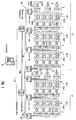
- FIG. 1 the configuration of an electric multi-drive system is practical for one Shaftless "newspaper printing machine shown.
- a plurality of drive units usually consisting of an electric motor M and a converter BKH, is used to move or rotate functional parts such as printing units DW1 ... 4, each with printing cylinders 3, folding units FE1, FE2 or others Functional parts 5.
- four printing units 1 ... 4 are combined to form a printing unit DE1, DE2, DE3, DE4, DE5, ...
- the first three printing units DE1, DE2, DE3 form FE1 and other functional parts 5, a first section 1, the other two printing units DE4, DE5 a second section 2, and further functional parts can in principle form any number of other sections, for controlling and regulating the drive units 1 of each section S1, S2, ... respective signal processing networks N1, N2, ... arranged, which consist of master signal processing computers or master nodes Ma1, Ma2, ... and several with these networked slave signal processing computers or slave nodes DSP-MAR exist.
- the latter are designed as multi-axis controllers and, according to the example shown, can control or otherwise control up to four motor axes simultaneously via two connected APM axis / peripheral module pairs (cf.
- Communication within a local signal processing network N1, N2, ... takes place via serial-synchronous communication interfaces (see, for example, SERCOS interface sources mentioned at the beginning) in the context of a serial, ring-like section bus SB. Communication is controlled and monitored by the respective master node Ma1, Ma2, ... These can also exchange data and commands bidirectionally with one another, for which purpose a separate master bus MB is provided as the communication system.
- a control center bus LB is formed which connects the master nodes Ma2 respective control communication interfaces LKS with a control center computer system 6 connects. From this the master node can set specifications and parameters in particular to form a virtual master axis for the assigned section 1, section 2, ... to receive the respective section control SLS1, SLS2, ... form.
- the MB master bus system can link and / or coupling them via the MB master bus system can with the drawn machine, for example a newspaper printing machine, realize a production and / or an operation in which cross-section Work processes can be set up flexibly.
- each of the local networks N1, N2,..., N32 contains a master node or master signal processing computer Ma and 12 slave nodes or slave signal processing computer DSP-MAR, each for multi-axis control, in the example shown for four-axis control , are trained.
- Communication within a local network takes place, as in FIG. 1, by means of serial-synchronous interfaces SSK.
- this serial bus system is also used to implement the master bus MB in order to couple, synchronize or otherwise network the respective master nodes of the local or section signal processing networks N1, N2,..., N32. Consequently, each master node Ma or each section control axis controller SLS1, SLS2, ..., SLS32 is provided with two serial-synchronous communication interfaces SSK. Communication in the section network N1, N2,...
- N32 is dominated by the first one, communication by the master nodes to one another in order to implement the distributed virtual master axis. It is expedient to use one of the master nodes forming a master network LN as global master "and the remaining as global slaves "in order to be able to implement the transmission of synchronization information relating to virtual master axes.
- the master function in one of the master nodes is twice, as it were - once for the network N1, N2, ... N32 of the section master controller SL1, SL2 ,. .SL32, once for the control network LN of the remaining master nodes Ma2, Ma3, ..., Ma32 - to implement, while in the remaining master nodes both a master function Ma2, Ma3, ... Ma32 and a simultaneous slave function SL2, SL3 ,. .., SL32 are to be created.
- the drives coupled to a virtual master axis of a section master controller SLS can be divided into further, for example 16 groups.
- special functions are available, such as the color and cut register, additive Speed setpoints and homing commands.
- each section control axis control SLS1, SLS2, ... SLS32 is on one higher-level control center level a programmable logic controller SPS1, SPS2, ..., SPS32 assigned, whereby the communication is also via serial synchronous Interfaces SSK can take place.
- This can be done from a control center Influence on the generation of the virtual leading axis in the respective Section master axis control SLS1, SLS2, ..., SLS32 can be influenced.
- This Possibility can be used specifically to check the color and cut register, a pre / post-lag pressure rollers or web tension control.
Landscapes
- Engineering & Computer Science (AREA)
- Human Computer Interaction (AREA)
- Manufacturing & Machinery (AREA)
- Physics & Mathematics (AREA)
- General Physics & Mathematics (AREA)
- Automation & Control Theory (AREA)
- Control Of Multiple Motors (AREA)
- Inking, Control Or Cleaning Of Printing Machines (AREA)
Abstract
Description
- Fig. 1
- ein erfindungsgemäßes Antriebssystem in seiner Grundstruktur,
- Fig. 2
- ein erfindungsgemäßes Antriebssystem mit einem ringartig strukturierten Leitnetzwerk.
Claims (20)
- Elektrisches Antriebssystem zur Verstellung von mehreren, insbesondere einer Vielzahl von Achsen oder sonstigen bewegbaren Funktionsteilen (DW1-4,3,5) eines Gerätes oder einer Maschine, insbesondere von Zylindern (3) oder Walzen von Druckmaschinen, in ihrer Lage, Geschwindigkeit oder Beschleunigung, mit mehreren elektromotorischen Antriebseinheiten (1), die jeweils mit wenigstens einem der Funktionsteile (DW1-4,3,FE1-FE2,5) verbunden sind, mit mehreren Signalverarbeitungsrechnern (Ma,DSP-MAR), die zur Aufnahme von Leit-, Steuer-, Soll- und/oder Lage-, Geschwindigkeits- und/oder Beschleunigungungssignalen von etwaigen Leitrechnern (6,SPS) oder Lagegebern an den Funktionsteilen (DW1-4,3,5) oder Läufern der Antriebseinheiten (1) ausgebildet und mit den Antriebseinheiten (1) zu deren steuerungs- oder regelungstechnischen Kontrolle verbunden sind, und mit mehreren, in sich geschlossenen Signalverarbeitungsnetzwerken (N1,N2,...,N32), die jeweils mehrere der Signalverarbeitungsrechner (Ma1-Ma32,DSP-MAR1.1-DSP-MAR32.12) als Knoten aufweisen und innerhalb des Geräts oder der Maschine einer Sektion beziehungsweise einem Verband von Funktionsteilen (DW1-4,3,FE1-FE2,5) zugeordnet sind, wobei innerhalb eines Netzwerks (N1) deren Knoten (Ma,DSP-MAR) nach dem Master/Slave-Prinzip angeordnet und durch Kommunikationskanäle und/oder ein Kommunikationssystem miteinander verbunden sind, und wenigstens ein Knoten eines Signalverarbeitungsnetzwerks (N1) mit einem Knoten eines anderen Signalverarbeitungsnetzwerks (N2,...,N32) gekoppelt ist, dadurch gekennzeichnet, daß die Signalverarbeitungsnetzwerke (N1 ,N2,...,N32) zur bidirektionalen Kommunikation und/oder Information untereinander jeweils über ihre Masterknoten (Ma1-Ma32) oder Master-Signalverarbeitungsrechner miteinander gekoppelt sind.
- Antriebssystem nach Anspruch 1, gekennzeichnet durch eine Kopplung der Masterknoten (Ma1-Ma32) derart, daß sie ein eigenes, in sich geschlossenes globales Leitnetzwerk (LN) bilden.
- Antriebssystem nach Anspruch 2, dadurch gekennzeichnet, daß die Rechnerknoten (Ma1-Ma32) des Leitnetzwerks (LN) in einer geschlossen ringartigen Struktur angeordnet sind.
- Antriebssystem nach Anspruch 2 oder 3, dadurch gekennzeichnet, daß die Rechnerknoten (Ma1-Ma32) des Leitnetzwerks (LN) miteinander über ein serielles Bussystem (MB,SSK) in Kommunikation stehen.
- Antriebssystem nach einem der Ansprüche 2 bis 4, dadurch gekennzeichnet, daß die Rechnerknoten (Ma1-Ma32) des Leitnetzwerks (LN) zueinander nach dem Master/Slave-Prinzip (Ma,S12-S132) angeordnet sind.
- Antriebssystem nach einem der vorangehenden Ansprüche, dadurch gekennzeichnet, daß ein oder mehrere der innerhalb eines Signalverarbeitungsnetzwerks (N1,N2,...N32) als Slaveknoten angeordneten Signalverabeitungsrechner (DSP-MAR) oder Antriebsregler zur gleichzeitigen Regelung oder sonstigen Kontrolle mehrerer Antriebseinheiten (1) ausgebildet sind.
- Antriebssystem nach einem der vorangehenden Ansprüche, dadurch gekennzeichnet, daß mindestens eines der Signalverarbeitungsnetzwerke (N1 ,N2,..,N3) mit einer Leitschnittstelle (LB,SSK) zu einem übergeordneten Leitsteuerungssystem, insbesondere zu dem Leitrechner (6), aufweist.
- Antriebssystem nach Anspruch 7, dadurch gekennzeichnet, daß das Leitsteuerungssystem, insbesondere der Leitrechner (6), über die Leitschnittstelle (LB,SSK) direkt mit dem jeweiligen Masterknoten (Ma1-Ma32) oder einem oder mehreren der Slaveknoten (DSP-MAR) zu deren direkter Ansteuerung verbindbar ist.
- Antriebssystem nach Anspruch 2 und gegebenenfalls einem der Ansprüche 3 bis 8, dadurch gekennzeichnet, daß eine oder mehrere Schnittstellen (Ma,SSK;S12-S132,SSK) der Master-Knoten (Ma1-Ma32), die der Kopplung der Masterknoten untereinander im Leitnetzwerk (LN) und der Kopplung mit den Slaveknoten (DSP-MAR) im jeweiligen lokalen Signalverarbeitungsnetzwerk (N1,N2,...,N32) dienen, mit Mitteln zur zeitlichen Koordination beziehungsweise Synchronisierung der gekoppelten Knoten versehen sind.
- Antriebssystem nach Anspruch 9, dadurch gekennzeichnet, daß die Synchronisierungsmittel Übertragungs- oder Sende- und Empfangseinrichtungen für Synchronisationssignale oder -zeichen, insbesondere -telegramme, zwischen den Knoten und/oder Mittel zur Ableitung oder Rückgewinnung eines Synchrontaktes aus erhaltenen Synchronisationssignalen oder -zeichen aufweisen.
- Antriebssystem nach Anspruch 10, dadurch gekennzeichnet, daß jeder Masterknoten (Ma1-Ma32) mit einer der Übertragungs- oder Sendeeinrichtung für Synchronisationssignale oder -zeichen, insbesondere -telegramme versehen ist.
- Antriebssystem nach Anspruch 10 oder 11, dadurch gekennzeichnet, daß jeder Master- und/oder Slaveknoten (Ma1-Ma32,DSP-MAR) mit den Mitteln zur Ableitung oder Rückgewinnung eines Synchrontaktes aus erhaltenen Synchronisationssignalen oder -zeichen versehen ist.
- Antriebssystem nach Anspruch 2 und gegebenenfalls einem der Ansprüche 3 bis 12, dadurch gekennzeichnet, daß im Leitnetzerk (LN) und/oder im jeweiligen Signalverarbeitungsnetzwerk (N1 ,N2,...,N32) der Masterknoten (Ma1) zur Kopplung mit einem anderen Masterknoten (Ma2,Ma3,...,Ma32) oder mit einem oder mehreren Slaveknoten (DSP-MAR) eine synchrone und/oder serielle Kommunikationsschnittstelle (SSK) aufweist.
- Antriebssystem nach einem der vorangehenden Ansprüche, dadurch gekennzeichnet, daß der in einem Signalverarbeitungsnetzwerk (N1) als Kommunikationsmaster dominierende Masterknoten (Ma1) zur Kopplung und/oder Synchronisation mit wenigstens einem Masterknoten (Ma2,Ma2,...,Ma32) eines anderen Signalverarbeitungsnetzwerkes (N2,N3,...,N32) ausgebildet und eingesetzt ist.
- Antriebssystem nach einem der vorangehenden Ansprüche, dadurch gekennzeichnet, daß die Masterknoten (Ma1,Ma2,...,Ma32) eines oder mehrerer oder aller Signalverarbeitungsnetzwerke (N1,N2,...,N32) in einer Ring- oder geschlossenen Schleifenstruktur (MB,SSK) verbunden sind und miteinander kommunizieren.
- Arbeits- oder Betriebsverfahren für ein Antriebssystem nach einem der vorangehenden Ansprüche, dadurch gekennzeichnet, daß in einem oder mehreren oder in allen Signalverarbeitungsnetzwerken (N1,N2,...,N32) jeweils eine virtuelle Leitachse zur kinematischen Synchronisation der dem Signalverarbeitungsnetzwerk zugeordneten Funktionsteile (DW1-DW4,3,FE1-FE2,5) generiert wird.
- Arbeits- oder Betriebsverfahren nach Anspruch 16, dadurch gekennzeichnet, daß die Synchronisationssignale entsprechend der virtuellen Leitachse eines Signalverarbeitungsnetzwerks (N1) aus diesem zu einem oder mehreren anderen Signalverarbeitungsnetzwerken (N2-N32) übertragen und zur Synchronisation dort angeschlossener Antriebseinheiten (1) verwendet werden.
- Arbeits- oder Betriebsverfahren nach Anspruch 16 oder 17, dadurch gekennzeichnet, daß eine oder mehrere der Antriebseinheiten (1) eines oder mehrerer der Signalverarbeitungsnetzwerke (N1) über die Kopplung der Master-Signalverarbeitungsrechner oder Masterknoten (Ma1 ,Ma2,...,Ma32) nach einer virtuellen Leitachse eines anderen Signalverarbeitungsnetzwerkes (N2,N3,...,N32) betrieben werden.
- Arbeits- oder Betriebsverfahren nach Anspruch 17 oder 18, dadurch gekennzeichnet, daß die nach einer gemeinsamen virtuellen Leitachse betriebenen Antriebseinheiten (1) in unterschiedliche Gruppen untergliedert und zur koordinierten Ausführung von je einer Gruppe zugeordneten Funktionen eingesetzt werden, die synchron zur virtuellen Leitachse ablaufen.
- Arbeits- oder Betriebsverfahren nach einem der vorangehenden Ansprüche, für ein Antriebssystem nach Ansprüche 7 oder 8, dadurch gekennzeichnet, daß im Signalverarbeitungsnetzwerk (N1,N2,...,N32) die virtuelle Leitachse über die Leitschnittstelle (LB,SSK) aus Vorgaben des Leitsteuerungssystems, insbesondere Leitrechners (6), abgeleitet wird.
Applications Claiming Priority (2)
| Application Number | Priority Date | Filing Date | Title |
|---|---|---|---|
| DE19801754 | 1998-01-20 | ||
| DE19801754 | 1998-01-20 |
Publications (2)
| Publication Number | Publication Date |
|---|---|
| EP0930552A2 true EP0930552A2 (de) | 1999-07-21 |
| EP0930552A3 EP0930552A3 (de) | 1999-12-08 |
Family
ID=7854995
Family Applications (1)
| Application Number | Title | Priority Date | Filing Date |
|---|---|---|---|
| EP99100861A Withdrawn EP0930552A3 (de) | 1998-01-20 | 1999-01-19 | Elektrisches Antriebssystem mit verteilter, virtueller Leitachse |
Country Status (1)
| Country | Link |
|---|---|
| EP (1) | EP0930552A3 (de) |
Cited By (14)
| Publication number | Priority date | Publication date | Assignee | Title |
|---|---|---|---|---|
| EP1080893A1 (de) * | 1999-08-30 | 2001-03-07 | Tokyo Kikai Seisakusho Ltd. | Netzwerksteuerungssystem für Rotationsdruckmaschinen |
| EP1151865A2 (de) * | 2000-04-28 | 2001-11-07 | Tokyo Kikai Seisakusho Ltd. | Synchrone Regelung von Rotationsdruckmaschinen |
| EP1167035A2 (de) * | 2000-06-23 | 2002-01-02 | Tokyo Kikai Seisakusho Ltd. | Synchrone Regelung mit automatischen Registerfunktionen für das Schneiden und Drucken |
| EP1190856A1 (de) * | 2000-09-22 | 2002-03-27 | Tokyo Kikai Seisakusho Ltd. | Synchrone Steuereinrichtung einer Rotationsdruckmaschine zum Auswählen des Steuersubjektes auf Basis der Information von Druckbildern |
| EP1223034A2 (de) * | 2001-01-11 | 2002-07-17 | Tokyo Kikai Seisakusho Ltd. | Synchrone Steuervorrichtung einer Rotationsdruckmaschine für das Auswählen des Steuerziels basiert auf Druckbildinformationen |
| WO2002082192A2 (de) * | 2001-04-06 | 2002-10-17 | Rexroth Indramat Gmbh | Verfahren zum synchronisierten betrieb von maschinen mit durch einzelantriebe angetriebenen achsen |
| EP1361049A2 (de) | 2000-09-20 | 2003-11-12 | Koenig & Bauer Aktiengesellschaft | Druckeinheit |
| EP1658974A2 (de) * | 2002-09-19 | 2006-05-24 | Koenig & Bauer Aktiengesellschaft | Antriebsvorrichtungen einer Bearbeitungsmaschine mit mehreren Aggregaten |
| EP1772263A1 (de) | 2005-10-07 | 2007-04-11 | Bosch Rexroth AG | Rotationsdruckmaschine und Verfahren des Betriebs einer Rotationsdruckmaschine |
| EP2243630A1 (de) * | 2009-04-24 | 2010-10-27 | Baumüller Anlagen-Systemtechnik GmbH & Co. KG | Rotations-Druckmaschine mit Synchronisation der Falz-Antriebsgruppe |
| EP2286996A1 (de) * | 2009-08-21 | 2011-02-23 | Baumüller Anlagen-Systemtechnik GmbH & Co. KG | Verfahren zur Herstellung eines positionssynchronen Antriebsverbundes durch Vorgabe einer Geschwindigkeits- und Positionsreferenz sowie Antriebssystem zu dessen Durchführung |
| EP2002980A3 (de) * | 2007-04-10 | 2011-08-03 | Robert Bosch Gmbh | Verfahren zum Betreiben einer Druckmaschine |
| US7992492B2 (en) | 2005-10-07 | 2011-08-09 | Bosch Rexroth Ag | Web offset printing press and method for operating a web offset printing press |
| DE10248690B4 (de) * | 2001-11-15 | 2019-10-31 | Heidelberger Druckmaschinen Ag | Verfahren zur Synchronisation mehrerer elektrischer Antriebseinheiten |
Citations (5)
| Publication number | Priority date | Publication date | Assignee | Title |
|---|---|---|---|---|
| US5361260A (en) * | 1991-03-22 | 1994-11-01 | Mitsubishi Denki Kabushiki Kaisha | Communication system |
| DE19527199A1 (de) * | 1995-07-26 | 1997-01-30 | Baumueller Nuernberg Gmbh | Flexodruckmaschine und deren Verwendung |
| EP0812683A1 (de) * | 1996-06-11 | 1997-12-17 | MAN Roland Druckmaschinen AG | Antrieb für eine Druckmaschine |
| EP0816963A2 (de) * | 1996-07-01 | 1998-01-07 | Asea Brown Boveri AG | Verfahren zum Betrieb eines Antriebssystems und Vorrichtung zur Durchführung des Verfahrens |
| DE19633745A1 (de) * | 1996-08-22 | 1998-02-26 | Baumueller Anlagen Systemtech | Mehrere Netzwerke zur Signalverarbeitung in einem elektrischen Antriebssystem |
-
1999
- 1999-01-19 EP EP99100861A patent/EP0930552A3/de not_active Withdrawn
Patent Citations (5)
| Publication number | Priority date | Publication date | Assignee | Title |
|---|---|---|---|---|
| US5361260A (en) * | 1991-03-22 | 1994-11-01 | Mitsubishi Denki Kabushiki Kaisha | Communication system |
| DE19527199A1 (de) * | 1995-07-26 | 1997-01-30 | Baumueller Nuernberg Gmbh | Flexodruckmaschine und deren Verwendung |
| EP0812683A1 (de) * | 1996-06-11 | 1997-12-17 | MAN Roland Druckmaschinen AG | Antrieb für eine Druckmaschine |
| EP0816963A2 (de) * | 1996-07-01 | 1998-01-07 | Asea Brown Boveri AG | Verfahren zum Betrieb eines Antriebssystems und Vorrichtung zur Durchführung des Verfahrens |
| DE19633745A1 (de) * | 1996-08-22 | 1998-02-26 | Baumueller Anlagen Systemtech | Mehrere Netzwerke zur Signalverarbeitung in einem elektrischen Antriebssystem |
Cited By (27)
| Publication number | Priority date | Publication date | Assignee | Title |
|---|---|---|---|---|
| EP1080893A1 (de) * | 1999-08-30 | 2001-03-07 | Tokyo Kikai Seisakusho Ltd. | Netzwerksteuerungssystem für Rotationsdruckmaschinen |
| EP1151865A2 (de) * | 2000-04-28 | 2001-11-07 | Tokyo Kikai Seisakusho Ltd. | Synchrone Regelung von Rotationsdruckmaschinen |
| EP1151865A3 (de) * | 2000-04-28 | 2002-09-11 | Tokyo Kikai Seisakusho Ltd. | Synchrone Regelung von Rotationsdruckmaschinen |
| US6568323B2 (en) | 2000-06-23 | 2003-05-27 | Tokyo Kikai Seisakusho, Ltd. | Synchronous control system having automatic cutting and printing registering functions |
| EP1167035A2 (de) * | 2000-06-23 | 2002-01-02 | Tokyo Kikai Seisakusho Ltd. | Synchrone Regelung mit automatischen Registerfunktionen für das Schneiden und Drucken |
| EP1595702A3 (de) * | 2000-06-23 | 2006-07-05 | Tokyo Kikai Seisakusho, Ltd. | Synchrone Regelung mit automatischen Registerfunktionen für das Schneiden und Drucken |
| EP1167035A3 (de) * | 2000-06-23 | 2002-09-11 | Tokyo Kikai Seisakusho Ltd. | Synchrone Regelung mit automatischen Registerfunktionen für das Schneiden und Drucken |
| US6626102B2 (en) | 2000-06-23 | 2003-09-30 | Tokyo Kikai Seisakusho, Ltd. | Synchronous control system having automatic cutting and printing registering functions |
| EP1361049A3 (de) * | 2000-09-20 | 2008-07-09 | Koenig & Bauer Aktiengesellschaft | Druckeinheit |
| EP1361049A2 (de) | 2000-09-20 | 2003-11-12 | Koenig & Bauer Aktiengesellschaft | Druckeinheit |
| EP1190856A1 (de) * | 2000-09-22 | 2002-03-27 | Tokyo Kikai Seisakusho Ltd. | Synchrone Steuereinrichtung einer Rotationsdruckmaschine zum Auswählen des Steuersubjektes auf Basis der Information von Druckbildern |
| EP1223034A3 (de) * | 2001-01-11 | 2004-02-04 | Tokyo Kikai Seisakusho Ltd. | Synchrone Steuervorrichtung einer Rotationsdruckmaschine für das Auswählen des Steuerziels basiert auf Druckbildinformationen |
| EP1223034A2 (de) * | 2001-01-11 | 2002-07-17 | Tokyo Kikai Seisakusho Ltd. | Synchrone Steuervorrichtung einer Rotationsdruckmaschine für das Auswählen des Steuerziels basiert auf Druckbildinformationen |
| WO2002082192A2 (de) * | 2001-04-06 | 2002-10-17 | Rexroth Indramat Gmbh | Verfahren zum synchronisierten betrieb von maschinen mit durch einzelantriebe angetriebenen achsen |
| US6914402B2 (en) | 2001-04-06 | 2005-07-05 | Rexroth Indramat Gmbh | Method for synchronized operation of machines having axes actuated by single drives |
| WO2002082192A3 (de) * | 2001-04-06 | 2003-04-10 | Rexroth Indramat Gmbh | Verfahren zum synchronisierten betrieb von maschinen mit durch einzelantriebe angetriebenen achsen |
| DE10248690B4 (de) * | 2001-11-15 | 2019-10-31 | Heidelberger Druckmaschinen Ag | Verfahren zur Synchronisation mehrerer elektrischer Antriebseinheiten |
| EP1658974A2 (de) * | 2002-09-19 | 2006-05-24 | Koenig & Bauer Aktiengesellschaft | Antriebsvorrichtungen einer Bearbeitungsmaschine mit mehreren Aggregaten |
| EP1658974A3 (de) * | 2002-09-19 | 2006-06-07 | Koenig & Bauer Aktiengesellschaft | Antriebsvorrichtungen einer Bearbeitungsmaschine mit mehreren Aggregaten |
| US7448321B2 (en) | 2002-09-19 | 2008-11-11 | Koenig & Bauer Aktiengesellschaft | Drive devices and method for driving a processing machine |
| US7712415B2 (en) | 2002-09-19 | 2010-05-11 | Koenig & Bauer Aktiengesellschaft | Drive devices and method for driving a processing machine |
| EP1772263A1 (de) | 2005-10-07 | 2007-04-11 | Bosch Rexroth AG | Rotationsdruckmaschine und Verfahren des Betriebs einer Rotationsdruckmaschine |
| US7992492B2 (en) | 2005-10-07 | 2011-08-09 | Bosch Rexroth Ag | Web offset printing press and method for operating a web offset printing press |
| US7997202B2 (en) | 2005-10-07 | 2011-08-16 | Bosch Rexroth Ag | Web offset printing press and method for operating a web offset printing press |
| EP2002980A3 (de) * | 2007-04-10 | 2011-08-03 | Robert Bosch Gmbh | Verfahren zum Betreiben einer Druckmaschine |
| EP2243630A1 (de) * | 2009-04-24 | 2010-10-27 | Baumüller Anlagen-Systemtechnik GmbH & Co. KG | Rotations-Druckmaschine mit Synchronisation der Falz-Antriebsgruppe |
| EP2286996A1 (de) * | 2009-08-21 | 2011-02-23 | Baumüller Anlagen-Systemtechnik GmbH & Co. KG | Verfahren zur Herstellung eines positionssynchronen Antriebsverbundes durch Vorgabe einer Geschwindigkeits- und Positionsreferenz sowie Antriebssystem zu dessen Durchführung |
Also Published As
| Publication number | Publication date |
|---|---|
| EP0930552A3 (de) | 1999-12-08 |
Similar Documents
| Publication | Publication Date | Title |
|---|---|---|
| EP0852538B1 (de) | Wellenlose rotationsdruckmaschine | |
| DE10243454B4 (de) | Antriebsvorrichtung einer Bearbeitungsmaschine | |
| EP1657608B1 (de) | Verfahren und Vorrichtung zum Betreiben eines Netzwerkes | |
| EP0930552A2 (de) | Elektrisches Antriebssystem mit verteilter, virtueller Leitachse | |
| DE10047927B4 (de) | Verfahren zur Vernetzung einer Regelungseinheit mit einem oder mehreren Leistungsteilen | |
| DE10248690B4 (de) | Verfahren zur Synchronisation mehrerer elektrischer Antriebseinheiten | |
| EP0816963A2 (de) | Verfahren zum Betrieb eines Antriebssystems und Vorrichtung zur Durchführung des Verfahrens | |
| EP3632040B1 (de) | Verarbeitung von prozessdaten | |
| EP0993698B2 (de) | Verfahren und vorrichtung zum dezentralen betrieb bzw aufbau einer winkelgenauen gleichlaufregelung in einem mehrmotorenantriebssystem | |
| DE102013106497B4 (de) | Master-Vorrichtung zur Anpassung der Datenübertragungsgeschwindigkeit nach kompletter Vorbereitung des Motorantriebs | |
| AT14695U1 (de) | Serielles Bussystem mit Koppelmodulen | |
| DE10047924B4 (de) | Antriebsregelung sowie Verfahren zur Vernetzung einer Regelungseinheit mit einem oder mehreren Gebersystemen | |
| EP0965165B1 (de) | Verfahren und vorrichtung zur aufrechterhaltung eines winkelgenauen gleichlaufs einzelner vernetzter antriebe eines dezentralen antriebssystems | |
| DE10317570B3 (de) | Antriebsvorrichtung eines Aggregates einer Druckmaschine | |
| DE19633745C2 (de) | Mehrere Netzwerke zur Signalverarbeitung in einem elektrischen Antriebssystem | |
| EP1426774B1 (de) | Anordnung bestehend aus einem ersten Halbleiter-Baustein und einem mit diesem verbundenen zweiten Halbleiter-Baustein | |
| EP1051670B1 (de) | Verfahren zum steuern mehrerer schrittmotormodule mit vorherigem laden von rampendaten | |
| EP2171554B1 (de) | Verfahren und vorrichtung zum einstecken, sammeln oder zusammentragen einer vielzahl von flexiblen, flächigen produkten | |
| EP1550269B1 (de) | Kommunikationssystem | |
| EP1426775B1 (de) | Anordnung bestehend aus einem ersten Halbleiter-Baustein und einem mit diesem verbundenen zweiten Halbleiter-Baustein | |
| EP2243630B1 (de) | Rotations-druckmaschine mit synchronisation der falz-antriebsgruppe | |
| EP3631630B1 (de) | Verteilte verarbeitung von prozessdaten | |
| EP2607978A2 (de) | Steuergerät für ein Solarelement, Steuersystem für ein Solarfeld, Solarfeld und Verfahren zum Steuern eines Solarelements | |
| EP3632055B1 (de) | Übertragen von daten auf einem lokalbus | |
| EP3632066B1 (de) | Vorladen von instruktionen |
Legal Events
| Date | Code | Title | Description |
|---|---|---|---|
| PUAI | Public reference made under article 153(3) epc to a published international application that has entered the european phase |
Free format text: ORIGINAL CODE: 0009012 |
|
| AK | Designated contracting states |
Kind code of ref document: A2 Designated state(s): AT BE CH CY DE DK ES FI FR GB GR IE IT LI LU MC NL PT SE |
|
| AX | Request for extension of the european patent |
Free format text: AL;LT;LV;MK;RO;SI |
|
| PUAL | Search report despatched |
Free format text: ORIGINAL CODE: 0009013 |
|
| AK | Designated contracting states |
Kind code of ref document: A3 Designated state(s): AT BE CH CY DE DK ES FI FR GB GR IE IT LI LU MC NL PT SE |
|
| AX | Request for extension of the european patent |
Free format text: AL;LT;LV;MK;RO;SI |
|
| RIC1 | Information provided on ipc code assigned before grant |
Free format text: 6G 05B 19/408 A, 6B 41F 13/004 B |
|
| AKX | Designation fees paid | ||
| REG | Reference to a national code |
Ref country code: DE Ref legal event code: 8566 |
|
| STAA | Information on the status of an ep patent application or granted ep patent |
Free format text: STATUS: THE APPLICATION IS DEEMED TO BE WITHDRAWN |
|
| 18D | Application deemed to be withdrawn |
Effective date: 20000608 |