EP0930440B1 - Mutter für Platten - Google Patents
Mutter für Platten Download PDFInfo
- Publication number
- EP0930440B1 EP0930440B1 EP99300159A EP99300159A EP0930440B1 EP 0930440 B1 EP0930440 B1 EP 0930440B1 EP 99300159 A EP99300159 A EP 99300159A EP 99300159 A EP99300159 A EP 99300159A EP 0930440 B1 EP0930440 B1 EP 0930440B1
- Authority
- EP
- European Patent Office
- Prior art keywords
- nut
- panel
- sleeve
- base plate
- locking
- Prior art date
- Legal status (The legal status is an assumption and is not a legal conclusion. Google has not performed a legal analysis and makes no representation as to the accuracy of the status listed.)
- Expired - Lifetime
Links
- 239000002184 metal Substances 0.000 claims description 9
- 230000001154 acute effect Effects 0.000 claims description 2
- 230000015572 biosynthetic process Effects 0.000 description 2
- 238000009434 installation Methods 0.000 description 2
- 229910000831 Steel Inorganic materials 0.000 description 1
- 230000006835 compression Effects 0.000 description 1
- 238000007906 compression Methods 0.000 description 1
- 238000010276 construction Methods 0.000 description 1
- 230000014759 maintenance of location Effects 0.000 description 1
- 238000000034 method Methods 0.000 description 1
- 230000000750 progressive effect Effects 0.000 description 1
- 239000010959 steel Substances 0.000 description 1
Images

Classifications
-
- F—MECHANICAL ENGINEERING; LIGHTING; HEATING; WEAPONS; BLASTING
- F16—ENGINEERING ELEMENTS AND UNITS; GENERAL MEASURES FOR PRODUCING AND MAINTAINING EFFECTIVE FUNCTIONING OF MACHINES OR INSTALLATIONS; THERMAL INSULATION IN GENERAL
- F16B—DEVICES FOR FASTENING OR SECURING CONSTRUCTIONAL ELEMENTS OR MACHINE PARTS TOGETHER, e.g. NAILS, BOLTS, CIRCLIPS, CLAMPS, CLIPS OR WEDGES; JOINTS OR JOINTING
- F16B37/00—Nuts or like thread-engaging members
- F16B37/04—Devices for fastening nuts to surfaces, e.g. sheets, plates
- F16B37/041—Releasable devices
- F16B37/043—Releasable devices with snap action
-
- F—MECHANICAL ENGINEERING; LIGHTING; HEATING; WEAPONS; BLASTING
- F16—ENGINEERING ELEMENTS AND UNITS; GENERAL MEASURES FOR PRODUCING AND MAINTAINING EFFECTIVE FUNCTIONING OF MACHINES OR INSTALLATIONS; THERMAL INSULATION IN GENERAL
- F16B—DEVICES FOR FASTENING OR SECURING CONSTRUCTIONAL ELEMENTS OR MACHINE PARTS TOGETHER, e.g. NAILS, BOLTS, CIRCLIPS, CLAMPS, CLIPS OR WEDGES; JOINTS OR JOINTING
- F16B37/00—Nuts or like thread-engaging members
- F16B37/02—Nuts or like thread-engaging members made of thin sheet material
Definitions
- the present invention relates to a fastener system and, more particularly, to a nut for locking receipt within a panel opening formed from a sheetlike metal blank.
- a nut for locking receipt within a panel opening formed from a sheetlike metal blank comprises:
- portion of the locking strips and the securing means closest to the sleeve axis extend into a projection of the bore of the sleeve.
- a fastening combination comprises a nut in accordance with the first aspect of the invention and a member received within the sleeve and having parts urging the locking strips and securing means outwards, away from the sleeve axis and, in use, into contact with the panel.
- a fastener system for mounting an object to a panel opening solely from a first side of the panel, comprises:
- the fastener nut is constructed from a blank or strip of sheet metal stamped and formed into final configuration.
- a central part of the fastener includes a sleeve extending from a surface thereof and which is provided with one or more internal threads for accommodating a screw or bolt therein.
- Wing-like side portions are arranged at two opposite sides of the threaded sleeve and extend in a common direction so as to pass through the opening in a panel during mounting use.
- Each of the wing portions includes first locking parts which snap into place on the far side of the panel when the nut is mounted thereto and by virtue of inherent spring characteristic of the sheet metal automatically spring outwardly to lockingly obstruct removal of the nut from the opening. Further locking portions directly engage the edge of the panel opening for frictionally resisting removal of the nut once it is mounted within the opening as well as insuring locking retention and preventing transverse movement of the nut within the opening.
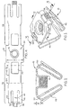
- FIG. 1 where the nut of the invention is enumerated generally as 10 and includes in its major parts base plate 12 which abuts against a major surface of a panel 14 in a way that will be described when a sleeve 16 integral with the base plate is fully extended through a panel opening 18.
- first locking means 20 which automatically extend to a position opposite the lower major surface 22 of the panel to which the nut is affixed and also second locking means 24 which frictionally contact the panel opening 18 edges (FIG. 5).
- the combined action of the locking means 20 and 24 serve to fully secure the nut within opening 18 of the panel enabling receipt of a threaded bolt 26 therewithin and securing other apparatus to the panel which other apparatus is more generally shown and enumerated as 28.
- the blank made of sheet metal (e.g., steel) from which the nut 10 of this invention is formed.
- the blank includes a central generally rectangular base plate (identical to base plate 12) having an edge dimension D which exceeds the width of panel opening 18 and in that way will prevent the nut from passing completely through the opening 18.
- a sleeve 16 either drawn or roll-formed, is provided in upstanding relation in the central region of the base plate and includes one or more internal threads.
- First and second identical sets of sidewall members 36 and 38 extend from opposite sides of the base 12 in opposite directions from one another and generally at 90 degrees to the base sidewall.
- the sidewall member 36 includes a generally rectangular extension 40 with an included opening 42 formed at the adjacent edge of the base plate, which opening primarily serves to reduce spring resistance in that region and in that way reduce nut installation force.
- the extension 40 includes first and second generally rectangular, elongated, locking strips 44 and 46 in spaced apart and generally parallel relation. The two sets of locking strips collectively form the first locking means 20.
- a panel edge securing means 48 which is substantially rectangular and extends generally parallel to the adjacent locking strips.
- the outer end portion 50 of the panel edge securing means 48 is provided with a good frictional surface such as, for example, by knurling.
- the dotted lines 52, 54 and 56 on the blank 30 are bend lines for forming the blank component parts into the desired shape of the nut 10.
- the blank 30 is formed to desired shape by a conventional press or stamping process.
- the bend lines should be sufficiently radiused so as not to weaken the resulting nut construction by the inclusion of sharp corners.
- the blank is treated preferably by a set of conventional progressive dies (not shown) which successively apply pressure to the blank metal for drawing or roll-forming the sleeve 16 and then accomplish internal threading of the sleeve.
- the panel edge securing means 48 have their outer end portions 50 on the major surface facing in the same direction that the sleeve extends treated to provide a scored surface with relatively sharp ridges facing outwardly from the metal surface for biting into the panel opening inner edge during use.
- the ridges extend at an angle that will provide a good gripping engagement with the inner edges of panel opening 18 (e.g., generally parallel to opening edges as in FIG. 3, or at an angle differing from 90 degree engagement with opening edges as in FIG. 1).
- the strips 44 and 46 and the means 48 are bent along the bend lines 52 - 56 in order to provide the final arrangement as shown in FIGS. 1 and 2, for example. More particularly, in final formed condition, the two extensions 40 are bent about the respective lines 52 so as to extend angularly toward each other with the further bend line 54 lying within the projected cross sectional area of the sleeve bore (FIG. 2). Also, strips 44, 46 and means 48 are bent about line 54 so as to be outward of the respectively adjacent extension 40 and generally parallel thereto. Still further, the outer end portion 50 is bent about line 52 toward the extension 40 so the tip 58 of means 48 is just within the opening 42 (FIG. 1).
- the nut 10 is received within the generally rectangular opening 18 in the panel 14 which is appropriately dimensioned for sliding receipt of the nut therein.
- the strips are laterally compressed slightly and so dimensioned that as the strip ends 60 extend completely through the opening, they spring laterally outwardly behind the panel edges now preventing withdrawal of the nut therefrom.
- the means 48 are positioned inwardly of strips 44 and 46 (FIG. 2) sufficiently so that when the nut is inserted in the panel opening the means 48 pass through the opening with at most only slight compression.
- the specially prepared frictional end portions 50 of the means 48 are located in slightly spaced or barely contacting relation with the edge portions of the panel opening. Accordingly, installation force of the nut into the panel opening is determined substantially solely by the spring reaction caused by the strips 44 and 46 as they pass through the panel opening.
- the tips 60 of strips 44 and 46 contact the lower surface of panel 24 when bolt 62 is fully received within the nut.
- the spacing ⁇ (FIG. 2 ) between tips 60 and the base plate 12 is made so as to enable accommodating a range of panel thicknesses as opposed to a single precise thickness, for example.
- the nut of the invention when the nut of the invention is mounted into a panel opening, it is not only prevented from being withdrawn from the opening without special tooling, but also provides a firm and reliable positioning of the nut within the opening which is desirable and promotes ease of mounting of a bolt with associated apparatus to the nut.
Landscapes
- Engineering & Computer Science (AREA)
- General Engineering & Computer Science (AREA)
- Mechanical Engineering (AREA)
- Dowels (AREA)
- Connection Of Plates (AREA)
- Body Structure For Vehicles (AREA)
Claims (10)
- Mutter (10) zur arretierenden Aufnahme innerhalb einer Plattenöffnung, die aus einem blechartigen Metallzuschnitt geformt ist, umfassend;eine Grundplatte (12);eine Hülse (16), die mit der Hauptfläche der Grundplatte (12) eine Einheit bildet und sich von dieser erhebt;erste und zweite beabstandete, mit der Grundplatte integrale Arretierlaschen (44, 46), die von jeder von zwei gegenüberliegenden Seitenkanten der Grundplatte abstehen und so geformt sind, dass sie sich in einem spitzen Winkel zu einer Hülsenachse hin erstrecken; undein erstes und ein zweites Sicherungsmittel (48), die jeweils als Einheit zwischen den ersten und zweiten Arretierlaschen angeordnet sind, wobei jedes der Sicherungsmittel einen Endabschnitt (50) mit hoher Reibung aufweist.
- Mutter nach Anspruch 1, wobei sich Abschnitte der Arretierlaschen (44, 46) und der Sicherungsmittel (48), die sich am nächsten an der Hülsenachse befinden, in eine Projektion der Hülsenbohrung (16) erstrecken.
- Mutter nach Anspruch 1 oder 2, wobei die Endabschnitte (50) mit hoher Reibung mehr als einen erhabenen Grat enthalten.
- Befestigungskombination, umfassend eine Mutter nach einem der vorangehenden Ansprüche und ein Element (26), das von der Hülse (16) aufgenommen wird und Teile aufweist, welche die Arretierlaschen (44, 46) und Sicherungsmittel (48) nach außen, weg von der Hülsenachse, und bei Gebrauch in Berührung mit der Platte (14) pressen.
- Befestigungskombination nach Anspruch 4, bei der die Hülse (16) mit einem Innengewinde versehen ist und das Element einen Gewindebolzen (26) umfasst, der beim Vorrücken in die Hülse (16) sowohl die Arretierlaschen (44, 46) als auch die Sicherungsmittel (48) gegen die gegenüberliegende Hauptfläche der Platte beziehungsweise die Seitenwände der Plattenöffnung bewegt.
- Befestigungskombination nach Anspruch 4, bei der ein bolzenartiges Element (26) und eine Hülse (16) eine Kleinmmutter bilden.
- Befestigungssystem zur Montage eines Objekts an einer Plattenöffnung (18) nur von einer ersten Seite der Platte (14), umfassend:eine Mutter (10) miteiner Grundplatte (12), die so dimensioniert ist, dass ein Hindurchgehen durch die Plattenöffnung (18) verhindert wird,einer Hülse (16) auf der Grundplatte (12);ersten und zweiten Arretiermitteln (44, 46), die sich von gegenüberliegenden Seiten der Grundplatte (12) nach außen erstrecken, wobei die Arretiermittel (44, 46) federartige Eigenschaften und solche Abmessungen aufweisen, dass sie beim Hindurchgehen durch die Plattenöffnung (18) zusammengedrückt werden und, nachdem sie die Öffnung (18) passiert haben, sich nach außen aufweiten und so blockierend an einer gegenüberliegenden Seite der Platte (14) anliegen,Sicherungsmitteln (48) mit federartigen Eigenschaften, die sich von den selben zwei gegenüberliegenden Seiten der Grundplatte (12) wie die Arretiermittel (44, 46) nach außen erstrecken, wobei jedes dieser Mittel (48) verzahnte Endabschnitte (50) aufweist; undeinem bolzenähnlichen, in der Hülse (16) aufgenommenen Element (26), das einen Kopfabschnitt für das Befestigen des Objekts (28) an der Mutter (10) und der Platte (14) aufweist, wobei zu diesem Zeitpunkt ein Endabschnitt des Elements (26) mit dem Sicherungsmittel (48) in Kontakt gelangt und die verzahnten Endabschnitte (50) gegen gegenüberliegende Seitenwände der Plattenöffnung (18) bewegt, was eine Relativbewegung der Mutter (10) in Querrichtung innerhalb der Plattenöffnung (18) verhindert.
- Befestigungssystem nach Anspruch 7, bei dem die Arretiermittel (44, 46) so dimensioniert sind, dass äußere Spitzen der Arretiermittel einen Abstand (α) zu der Grundplatte (12) haben, der ausreicht, um die Montage des Befestigungssystems an Platten (14) mit einer Reihe von Dicken zu ermöglichen.
- Befestigungssystem nach Anspruch 7 oder 8, wobei die verzahnten Endabschnitte (50) Abschnitte mit erhabenem Grat aufweisen, die allgemein parallel zu den Innenkanten der Plattenöffnung (18) verlaufen.
- Befestigungssystem nach Anspruch 7 oder 8, wobei die verzahnten Endabschnitte (50) Abschnitte mit erhabenem Grat aufweisen, die sich über die Innenkante der Plattenöffnung (18) in einem Winkel ungleich 90 Grad erstrecken.
Applications Claiming Priority (2)
| Application Number | Priority Date | Filing Date | Title |
|---|---|---|---|
| US9348 | 1998-01-20 | ||
| US09/009,348 US5919019A (en) | 1998-01-20 | 1998-01-20 | Mid-panel nut |
Publications (2)
| Publication Number | Publication Date |
|---|---|
| EP0930440A1 EP0930440A1 (de) | 1999-07-21 |
| EP0930440B1 true EP0930440B1 (de) | 2003-04-02 |
Family
ID=21737095
Family Applications (1)
| Application Number | Title | Priority Date | Filing Date |
|---|---|---|---|
| EP99300159A Expired - Lifetime EP0930440B1 (de) | 1998-01-20 | 1999-01-11 | Mutter für Platten |
Country Status (4)
| Country | Link |
|---|---|
| US (1) | US5919019A (de) |
| EP (1) | EP0930440B1 (de) |
| CA (1) | CA2257391C (de) |
| DE (1) | DE69906400T2 (de) |
Cited By (1)
| Publication number | Priority date | Publication date | Assignee | Title |
|---|---|---|---|---|
| US7419206B2 (en) | 2006-07-28 | 2008-09-02 | Newfrey Llc | Interior trim fastener system |
Families Citing this family (76)
| Publication number | Priority date | Publication date | Assignee | Title |
|---|---|---|---|---|
| US6095734A (en) * | 1999-09-21 | 2000-08-01 | Transtechnology Corp. | Pushnut |
| US6283689B1 (en) * | 1999-11-26 | 2001-09-04 | American Engineered Components, Inc. | Insert fastener |
| KR20010059692A (ko) * | 1999-12-30 | 2001-07-06 | 이계안 | 모듈러 클립 |
| US7168138B2 (en) * | 2000-03-27 | 2007-01-30 | Newfrey Llc | Resilient clip fastener |
| US6629809B2 (en) | 2000-11-08 | 2003-10-07 | Termax Corporation | Sheet metal fastener with multiple engagement |
| US6908274B1 (en) * | 2000-11-20 | 2005-06-21 | Termax Corporation | Combination fastener |
| JP3699048B2 (ja) * | 2001-02-01 | 2005-09-28 | ハン イル エ ワ カンパニーリミテッド | 物品装着用クリップ |
| US11603050B2 (en) | 2006-11-29 | 2023-03-14 | Termax Company | Spring fastener |
| US7784159B2 (en) * | 2002-06-07 | 2010-08-31 | Termax Corporation | Fastener with ergonomic removal to insertion force ratio |
| US7640634B2 (en) * | 2002-06-07 | 2010-01-05 | Termax Corporation | Ergonomic fastener |
| US6718599B2 (en) | 2001-06-25 | 2004-04-13 | Termax Corporation | Spring fastener with ergonomically balanced removal to insertion force ratio |
| US6691380B2 (en) | 2001-07-31 | 2004-02-17 | Eustathios Vassiliou Revocable Trust | Fasteners of increased holding power |
| US6745440B2 (en) | 2001-07-31 | 2004-06-08 | Eustathios Vassiliou Revocable Trust | Increased holding power spring fasteners |
| US6726418B2 (en) * | 2001-09-19 | 2004-04-27 | Eustathios Vassiliou Revocable Trust | Spring fastener for connecting automotive components and other articles |
| EP1507981A1 (de) * | 2002-05-28 | 2005-02-23 | Newfrey LLC | Federbefestigungsclip und verfahren zu dessen herstellung |
| US7226260B2 (en) * | 2002-06-24 | 2007-06-05 | A. Raymond, Inc. | Sheet metal fastening clip |
| US6896461B2 (en) * | 2002-08-06 | 2005-05-24 | E. Vassiliou Revo Cable Tryst | Spring fastener for substrates of various thicknesses and respective vehicles |
| US20040081534A1 (en) * | 2002-08-06 | 2004-04-29 | Dickinson Daniel James | Fastener for connecting automotive components and other articles |
| US20040199650A1 (en) * | 2002-11-14 | 2004-10-07 | Howe John E. | System and methods for accelerating data delivery |
| US20050016116A1 (en) * | 2003-07-21 | 2005-01-27 | Siegel-Robert, Inc. | One-piece integrated snap fastening mechanism |
| US6976292B2 (en) * | 2003-08-28 | 2005-12-20 | Newfrey Llc | Resilient clip fastener |
| US7188392B2 (en) * | 2003-11-17 | 2007-03-13 | Termax Corporation | Spring fastener with highly improved lever/angle pulling force |
| US11261897B2 (en) * | 2003-11-17 | 2022-03-01 | Mag Daddy, LLC | Structural fastener |
| EP1568897B1 (de) * | 2003-12-19 | 2007-07-18 | Southco UK Limited | Einstückiges Aufnahmeelement für eine Befestigungsvorrichtung |
| US20050169727A1 (en) * | 2004-02-02 | 2005-08-04 | Cosenza Frank J. | Fastener component |
| US7789606B2 (en) | 2004-04-01 | 2010-09-07 | Illinois Tool Works Inc. | Push-in nut |
| US20050220563A1 (en) * | 2004-04-01 | 2005-10-06 | Kosidlo John M Iv | Push-in nut |
| US7086125B2 (en) * | 2004-04-23 | 2006-08-08 | Newfrey Llc | Multiple stage assembly assist fastener |
| US11784428B2 (en) * | 2018-08-20 | 2023-10-10 | Mag Daddy Llc | Structural fastener |
| FR2881802B1 (fr) * | 2005-02-07 | 2007-04-27 | Itw Fastex France Soc Par Acti | Cage pour dispositif de fixation et dispositif comportant une telle cage |
| DE102006019256B4 (de) * | 2006-04-26 | 2008-04-30 | A. Raymond Et Cie | Befestigungsvorrichtung |
| EP2182226B1 (de) * | 2006-04-26 | 2012-07-25 | A. Raymond et Cie. | Befestigungsvorrichtung |
| DE102006040042A1 (de) * | 2006-08-26 | 2008-03-20 | GM Global Technology Operations, Inc., Detroit | Verfahren und Vorrichtung zum Befestigen eines Airbags an einem Kraftfahrzeug |
| US7496993B2 (en) * | 2006-12-08 | 2009-03-03 | Illinois Tool Works Inc. | Retention clip |
| USD576481S1 (en) * | 2007-02-08 | 2008-09-09 | Piolax, Inc. | Nut |
| DE102007015129B3 (de) * | 2007-03-29 | 2008-08-28 | Itw Automotive Products Gmbh & Co. Kg | Nicht demontierbarer Clip aus Kunststoff |
| USD572580S1 (en) * | 2007-06-21 | 2008-07-08 | Piolax Inc. | Nut |
| US8875357B2 (en) * | 2008-07-09 | 2014-11-04 | Tinnerman Palnut Engineered Products, Inc. | Clip |
| DE102008039108B4 (de) * | 2008-08-21 | 2010-10-07 | A. Raymond Et Cie | Vorrichtung zum Befestigen eines Anbauteiles an einem Trägerteil |
| IT1391712B1 (it) * | 2008-09-17 | 2012-01-27 | Lolli | Metodo per la realizzazione di una ghiera filettata |
| US8835757B2 (en) | 2010-11-10 | 2014-09-16 | Oldcastle Precast, Inc. | Locking subgrade vault |
| US9161751B2 (en) * | 2010-12-02 | 2015-10-20 | Coloplast A/S | Suture system and assembly |
| US10197088B2 (en) | 2011-11-10 | 2019-02-05 | Oldcastle Precast, Inc. | Tamper resistant closure mechanism for a utility vault |
| US9346593B2 (en) * | 2011-11-10 | 2016-05-24 | Oldcastle Precast, Inc. | Tamper resistant closure mechanism for a utility vault |
| US8800120B2 (en) * | 2012-04-27 | 2014-08-12 | Newfrey Llc | High retention fastener |
| US9435099B2 (en) | 2012-11-16 | 2016-09-06 | Oldcastle Precast, Inc. | Locking subgrade vault |
| ITTO20130246A1 (it) * | 2013-03-26 | 2014-09-27 | Fiat Group Automobiles Spa | Dispositivo di collegamento provvisto di un riparo per coprire l'estremita' di uno stelo filettato |
| US9506495B2 (en) | 2013-06-21 | 2016-11-29 | Steering Solutions Ip Holding Corporation | Self-locking insert |
| ES2534340B1 (es) * | 2013-10-21 | 2016-02-19 | Illinois Tool Works Inc. | Tuerca de fijación |
| US9631662B2 (en) * | 2014-03-19 | 2017-04-25 | Ramco Specialties, Inc. | Spring clip apparatus |
| US9440596B2 (en) * | 2014-11-20 | 2016-09-13 | Ford Global Technologies, Llc | Retention clip for interior vehicle components |
| WO2016094795A1 (en) | 2014-12-11 | 2016-06-16 | A.K. Stamping Company, Inc. | Grounding clamps |
| US9562554B2 (en) * | 2015-01-16 | 2017-02-07 | A. Raymond Et Cie | Retainer assembly |
| US11234899B2 (en) * | 2017-05-11 | 2022-02-01 | Scalpal Llc | Grasping facilitators and uses thereof and kits involving the same |
| EP3577352B1 (de) | 2017-01-31 | 2022-03-09 | Illinois Tool Works Inc. | Ergonomische hutmuttersicherung |
| US11969864B2 (en) | 2017-05-11 | 2024-04-30 | Scalpal Llc | Multi-tier torque enhancer driver and/or receiver and method of using same |
| CN110388371A (zh) * | 2018-04-18 | 2019-10-29 | 伊利诺斯工具制品有限公司 | 一种螺母紧固夹和螺母紧固夹组件 |
| US11629742B2 (en) * | 2018-06-19 | 2023-04-18 | Illinois Tool Works Inc. | Box nut retainer |
| USD874913S1 (en) * | 2018-06-19 | 2020-02-11 | Illinois Tool Works Inc. | Nut retainer |
| USD886573S1 (en) * | 2018-06-29 | 2020-06-09 | Mafi Ab | Fastening device for antenna |
| US11619324B2 (en) * | 2018-08-20 | 2023-04-04 | Mag Daddy, LLC | Structural fastener |
| US11387608B2 (en) * | 2019-08-13 | 2022-07-12 | Pass & Seymour, Inc. | Electrical wiring device with flexible terminal for eliminating connection to ground |
| US11692581B2 (en) | 2019-08-22 | 2023-07-04 | Illinois Tool Works Inc. | Box nut retainer |
| USD904866S1 (en) | 2019-08-23 | 2020-12-15 | Illinois Tool Works Inc. | Nut retainer |
| USD888546S1 (en) * | 2019-08-23 | 2020-06-30 | Illinois Tool Works Inc. | Nut retainer |
| USD904865S1 (en) | 2019-08-23 | 2020-12-15 | Illinois Tool Works Inc. | Nut retainer |
| USD995278S1 (en) * | 2019-10-01 | 2023-08-15 | Illinois Tool Works Inc. | Nut retainer |
| CN111576699B (zh) * | 2020-04-18 | 2022-07-19 | 杭州斯泰新材料技术有限公司 | 具有螺母外套的螺母组件及其紧固组件 |
| USD1028701S1 (en) * | 2020-10-19 | 2024-05-28 | Illinois Tool Works Inc. | Nut |
| USD1029627S1 (en) * | 2020-12-23 | 2024-06-04 | Jonathan Winnie | Magnetic hook |
| US11639731B2 (en) * | 2021-01-29 | 2023-05-02 | A. Raymond Et Cie | Fastener clip |
| US20230398952A1 (en) * | 2022-06-09 | 2023-12-14 | Illinois Tool Works Inc. | Emblem Retainer |
| USD1039959S1 (en) * | 2022-07-28 | 2024-08-27 | Seakeeper, Inc. | Nut retainer |
| USD1039369S1 (en) * | 2022-07-28 | 2024-08-20 | Seakeeper, Inc. | Nut retainer |
| US20240068501A1 (en) * | 2022-08-31 | 2024-02-29 | Illinois Tool Works Inc. | Corner Engage Clip with Integral Support Flange |
| US20250341227A1 (en) * | 2024-05-02 | 2025-11-06 | Illinois Tool Works Inc. | Retainer for Panels of Varying Thickness |
Family Cites Families (7)
| Publication number | Priority date | Publication date | Assignee | Title |
|---|---|---|---|---|
| US4606688A (en) * | 1982-12-15 | 1986-08-19 | Eaton Corporation | Removable fastening assembly |
| US4610588A (en) * | 1984-07-24 | 1986-09-09 | Trw, Inc. | Fastener clip |
| US4595325A (en) * | 1984-09-28 | 1986-06-17 | Eaton Corporation | Self-locking prevailing torque fastener |
| US4897005A (en) * | 1987-04-01 | 1990-01-30 | Buell Industries, Inc. | Gutted U-nut |
| US4925351A (en) * | 1989-03-21 | 1990-05-15 | Trw, Inc. | Push-in fastener clip |
| US5306091A (en) * | 1993-07-19 | 1994-04-26 | Saturn Corporation | Sheet metal nut |
| FR2719347B1 (fr) * | 1994-04-27 | 1996-06-21 | Rapid Sa | Ecrou en forme de pince insérable sur le bord d'un panneau ou analogue. |
-
1998
- 1998-01-20 US US09/009,348 patent/US5919019A/en not_active Expired - Fee Related
- 1998-12-22 CA CA002257391A patent/CA2257391C/en not_active Expired - Fee Related
-
1999
- 1999-01-11 EP EP99300159A patent/EP0930440B1/de not_active Expired - Lifetime
- 1999-01-11 DE DE69906400T patent/DE69906400T2/de not_active Expired - Lifetime
Cited By (1)
| Publication number | Priority date | Publication date | Assignee | Title |
|---|---|---|---|---|
| US7419206B2 (en) | 2006-07-28 | 2008-09-02 | Newfrey Llc | Interior trim fastener system |
Also Published As
| Publication number | Publication date |
|---|---|
| CA2257391C (en) | 2002-09-17 |
| EP0930440A1 (de) | 1999-07-21 |
| DE69906400T2 (de) | 2003-10-30 |
| US5919019A (en) | 1999-07-06 |
| DE69906400D1 (de) | 2003-05-08 |
| CA2257391A1 (en) | 1999-07-20 |
Similar Documents
| Publication | Publication Date | Title |
|---|---|---|
| EP0930440B1 (de) | Mutter für Platten | |
| EP1510702B1 (de) | Federbefestigungsclip | |
| US7725991B2 (en) | Low insertion effort fastener with offset for wing | |
| EP0588467B1 (de) | In eine Wandöffnung einer Platte einsetzbares Schraubverbindungselement | |
| US7849567B2 (en) | Spring fastener with highly improved removal to insertion ratio | |
| US5067863A (en) | Channel nut | |
| US4714392A (en) | Self-locking sheet-metal nut | |
| US4470716A (en) | Fastener clip with slip-proof locking feature, joint structure using same and method for making same | |
| US4897005A (en) | Gutted U-nut | |
| EP0606068B1 (de) | Batterieklemme | |
| US7568868B2 (en) | Device for connecting a support element to an add-on piece | |
| US6688825B1 (en) | Nut and retainer fastener assembly for securing a nut to a panel, and method of fastener assembly manufacture | |
| US20230178904A1 (en) | Rail splice with interference features | |
| EP0176267A1 (de) | Selbst-schliessendes, überwiegend durch Federkraft wirkendes Befestigungselement | |
| US5347691A (en) | Clip assembly | |
| US3809139A (en) | Clinch-slide nut, panel assembly and method of forming same | |
| US20050226700A1 (en) | Push-in nut | |
| WO1992013202A1 (en) | Channel nut | |
| US3496980A (en) | Clip nut | |
| US4259767A (en) | Fastener | |
| JPH0429195B2 (de) | ||
| US5378097A (en) | Sheet metal nut for blind fastening | |
| US6439819B2 (en) | Progressively-formed clinch nut | |
| US4960354A (en) | Headed fastener retainer clip | |
| US20050220563A1 (en) | Push-in nut |
Legal Events
| Date | Code | Title | Description |
|---|---|---|---|
| PUAI | Public reference made under article 153(3) epc to a published international application that has entered the european phase |
Free format text: ORIGINAL CODE: 0009012 |
|
| AK | Designated contracting states |
Kind code of ref document: A1 Designated state(s): DE FR IT |
|
| AX | Request for extension of the european patent |
Free format text: AL;LT;LV;MK;RO;SI |
|
| 17P | Request for examination filed |
Effective date: 20000121 |
|
| AKX | Designation fees paid |
Free format text: DE FR IT |
|
| GRAH | Despatch of communication of intention to grant a patent |
Free format text: ORIGINAL CODE: EPIDOS IGRA |
|
| GRAH | Despatch of communication of intention to grant a patent |
Free format text: ORIGINAL CODE: EPIDOS IGRA |
|
| GRAA | (expected) grant |
Free format text: ORIGINAL CODE: 0009210 |
|
| AK | Designated contracting states |
Designated state(s): DE FR IT |
|
| REF | Corresponds to: |
Ref document number: 69906400 Country of ref document: DE Date of ref document: 20030508 Kind code of ref document: P |
|
| ET | Fr: translation filed | ||
| PLBE | No opposition filed within time limit |
Free format text: ORIGINAL CODE: 0009261 |
|
| STAA | Information on the status of an ep patent application or granted ep patent |
Free format text: STATUS: NO OPPOSITION FILED WITHIN TIME LIMIT |
|
| 26N | No opposition filed |
Effective date: 20040105 |
|
| PGFP | Annual fee paid to national office [announced via postgrant information from national office to epo] |
Ref country code: IT Payment date: 20070518 Year of fee payment: 9 |
|
| PG25 | Lapsed in a contracting state [announced via postgrant information from national office to epo] |
Ref country code: IT Free format text: LAPSE BECAUSE OF NON-PAYMENT OF DUE FEES Effective date: 20080111 |
|
| PGFP | Annual fee paid to national office [announced via postgrant information from national office to epo] |
Ref country code: FR Payment date: 20100205 Year of fee payment: 12 |
|
| PGFP | Annual fee paid to national office [announced via postgrant information from national office to epo] |
Ref country code: DE Payment date: 20100127 Year of fee payment: 12 |
|
| REG | Reference to a national code |
Ref country code: FR Ref legal event code: ST Effective date: 20110930 |
|
| PG25 | Lapsed in a contracting state [announced via postgrant information from national office to epo] |
Ref country code: FR Free format text: LAPSE BECAUSE OF NON-PAYMENT OF DUE FEES Effective date: 20110131 |
|
| REG | Reference to a national code |
Ref country code: DE Ref legal event code: R119 Ref document number: 69906400 Country of ref document: DE Effective date: 20110802 |
|
| PG25 | Lapsed in a contracting state [announced via postgrant information from national office to epo] |
Ref country code: DE Free format text: LAPSE BECAUSE OF NON-PAYMENT OF DUE FEES Effective date: 20110802 |