EP0930427A2 - Internal combustion engine and method for its mixture preparation - Google Patents
Internal combustion engine and method for its mixture preparation Download PDFInfo
- Publication number
- EP0930427A2 EP0930427A2 EP99100595A EP99100595A EP0930427A2 EP 0930427 A2 EP0930427 A2 EP 0930427A2 EP 99100595 A EP99100595 A EP 99100595A EP 99100595 A EP99100595 A EP 99100595A EP 0930427 A2 EP0930427 A2 EP 0930427A2
- Authority
- EP
- European Patent Office
- Prior art keywords
- internal combustion
- combustion engine
- engine according
- piston
- combustion chamber
- Prior art date
- Legal status (The legal status is an assumption and is not a legal conclusion. Google has not performed a legal analysis and makes no representation as to the accuracy of the status listed.)
- Granted
Links
Images


Classifications
-
- F—MECHANICAL ENGINEERING; LIGHTING; HEATING; WEAPONS; BLASTING
- F02—COMBUSTION ENGINES; HOT-GAS OR COMBUSTION-PRODUCT ENGINE PLANTS
- F02F—CYLINDERS, PISTONS OR CASINGS, FOR COMBUSTION ENGINES; ARRANGEMENTS OF SEALINGS IN COMBUSTION ENGINES
- F02F1/00—Cylinders; Cylinder heads
- F02F1/24—Cylinder heads
- F02F1/42—Shape or arrangement of intake or exhaust channels in cylinder heads
- F02F1/4214—Shape or arrangement of intake or exhaust channels in cylinder heads specially adapted for four or more valves per cylinder
-
- F—MECHANICAL ENGINEERING; LIGHTING; HEATING; WEAPONS; BLASTING
- F02—COMBUSTION ENGINES; HOT-GAS OR COMBUSTION-PRODUCT ENGINE PLANTS
- F02B—INTERNAL-COMBUSTION PISTON ENGINES; COMBUSTION ENGINES IN GENERAL
- F02B23/00—Other engines characterised by special shape or construction of combustion chambers to improve operation
- F02B23/08—Other engines characterised by special shape or construction of combustion chambers to improve operation with positive ignition
- F02B23/10—Other engines characterised by special shape or construction of combustion chambers to improve operation with positive ignition with separate admission of air and fuel into cylinder
- F02B23/104—Other engines characterised by special shape or construction of combustion chambers to improve operation with positive ignition with separate admission of air and fuel into cylinder the injector being placed on a side position of the cylinder
-
- F—MECHANICAL ENGINEERING; LIGHTING; HEATING; WEAPONS; BLASTING
- F02—COMBUSTION ENGINES; HOT-GAS OR COMBUSTION-PRODUCT ENGINE PLANTS
- F02B—INTERNAL-COMBUSTION PISTON ENGINES; COMBUSTION ENGINES IN GENERAL
- F02B31/00—Modifying induction systems for imparting a rotation to the charge in the cylinder
- F02B31/04—Modifying induction systems for imparting a rotation to the charge in the cylinder by means within the induction channel, e.g. deflectors
- F02B31/06—Movable means, e.g. butterfly valves
- F02B31/08—Movable means, e.g. butterfly valves having multiple air inlets, i.e. having main and auxiliary intake passages
- F02B31/085—Movable means, e.g. butterfly valves having multiple air inlets, i.e. having main and auxiliary intake passages having two inlet valves
-
- F—MECHANICAL ENGINEERING; LIGHTING; HEATING; WEAPONS; BLASTING
- F02—COMBUSTION ENGINES; HOT-GAS OR COMBUSTION-PRODUCT ENGINE PLANTS
- F02B—INTERNAL-COMBUSTION PISTON ENGINES; COMBUSTION ENGINES IN GENERAL
- F02B23/00—Other engines characterised by special shape or construction of combustion chambers to improve operation
- F02B23/08—Other engines characterised by special shape or construction of combustion chambers to improve operation with positive ignition
- F02B23/10—Other engines characterised by special shape or construction of combustion chambers to improve operation with positive ignition with separate admission of air and fuel into cylinder
- F02B2023/106—Tumble flow, i.e. the axis of rotation of the main charge flow motion is horizontal
-
- F—MECHANICAL ENGINEERING; LIGHTING; HEATING; WEAPONS; BLASTING
- F02—COMBUSTION ENGINES; HOT-GAS OR COMBUSTION-PRODUCT ENGINE PLANTS
- F02B—INTERNAL-COMBUSTION PISTON ENGINES; COMBUSTION ENGINES IN GENERAL
- F02B75/00—Other engines
- F02B75/12—Other methods of operation
- F02B2075/125—Direct injection in the combustion chamber for spark ignition engines, i.e. not in pre-combustion chamber
-
- F—MECHANICAL ENGINEERING; LIGHTING; HEATING; WEAPONS; BLASTING
- F02—COMBUSTION ENGINES; HOT-GAS OR COMBUSTION-PRODUCT ENGINE PLANTS
- F02F—CYLINDERS, PISTONS OR CASINGS, FOR COMBUSTION ENGINES; ARRANGEMENTS OF SEALINGS IN COMBUSTION ENGINES
- F02F1/00—Cylinders; Cylinder heads
- F02F1/24—Cylinder heads
- F02F1/242—Arrangement of spark plugs or injectors
-
- F—MECHANICAL ENGINEERING; LIGHTING; HEATING; WEAPONS; BLASTING
- F02—COMBUSTION ENGINES; HOT-GAS OR COMBUSTION-PRODUCT ENGINE PLANTS
- F02F—CYLINDERS, PISTONS OR CASINGS, FOR COMBUSTION ENGINES; ARRANGEMENTS OF SEALINGS IN COMBUSTION ENGINES
- F02F1/00—Cylinders; Cylinder heads
- F02F1/24—Cylinder heads
- F02F2001/241—Cylinder heads specially adapted to pent roof shape of the combustion chamber
-
- F—MECHANICAL ENGINEERING; LIGHTING; HEATING; WEAPONS; BLASTING
- F02—COMBUSTION ENGINES; HOT-GAS OR COMBUSTION-PRODUCT ENGINE PLANTS
- F02F—CYLINDERS, PISTONS OR CASINGS, FOR COMBUSTION ENGINES; ARRANGEMENTS OF SEALINGS IN COMBUSTION ENGINES
- F02F1/00—Cylinders; Cylinder heads
- F02F1/24—Cylinder heads
- F02F2001/244—Arrangement of valve stems in cylinder heads
- F02F2001/245—Arrangement of valve stems in cylinder heads the valve stems being orientated at an angle with the cylinder axis
-
- F—MECHANICAL ENGINEERING; LIGHTING; HEATING; WEAPONS; BLASTING
- F02—COMBUSTION ENGINES; HOT-GAS OR COMBUSTION-PRODUCT ENGINE PLANTS
- F02F—CYLINDERS, PISTONS OR CASINGS, FOR COMBUSTION ENGINES; ARRANGEMENTS OF SEALINGS IN COMBUSTION ENGINES
- F02F3/00—Pistons
- F02F3/26—Pistons having combustion chamber in piston head
-
- Y—GENERAL TAGGING OF NEW TECHNOLOGICAL DEVELOPMENTS; GENERAL TAGGING OF CROSS-SECTIONAL TECHNOLOGIES SPANNING OVER SEVERAL SECTIONS OF THE IPC; TECHNICAL SUBJECTS COVERED BY FORMER USPC CROSS-REFERENCE ART COLLECTIONS [XRACs] AND DIGESTS
- Y02—TECHNOLOGIES OR APPLICATIONS FOR MITIGATION OR ADAPTATION AGAINST CLIMATE CHANGE
- Y02T—CLIMATE CHANGE MITIGATION TECHNOLOGIES RELATED TO TRANSPORTATION
- Y02T10/00—Road transport of goods or passengers
- Y02T10/10—Internal combustion engine [ICE] based vehicles
- Y02T10/12—Improving ICE efficiencies
Definitions
- the present invention relates to an internal combustion engine per cylinder two inlet valves arranged side by side, at least one outlet valve, a substantially coaxial spark plug, an injector and a piston per cylinder.
- the present invention further relates to a method for mixture preparation in an internal combustion engine.
- Such an internal combustion engine is for example from the document US 4,617,896 known.
- this internal combustion engine are within the Intake pipe provided several inlet channels, which are the inlet valves can be assigned, and are partly within these inlet channels Throttle valves provided.
- the cylinder head connected to the intake manifold the engine has one of the intake valves common inlet channel into which an injection valve opens. Because of the design of the inlet channels can be in the common inlet channel before Intake valves a good mixture swirl take place. Is problematic however, that this mixture is not without significant flow losses introduced the inlet valves into the combustion chamber of the internal combustion engine can be.
- this embodiment is for internal combustion engines hardly suitable with direct petrol injection.
- the internal combustion engine has the features of Claim 1 on. So the injector is between the two Inlet valves and the portion adjacent to the two inlet valves arranged in the cylinder wall and the piston has a first and a second combustion chamber trough, the first and the second combustion chamber trough arranged at different distances from the injection valve are.
- the internal combustion engine works due to the arrangement of the injection valve as direct injection, which means that the mixture is only processed in the combustion chamber becomes.
- An improved mixture preparation is obtained by the piston reciprocating in the cylinder in coordination with the previous ones
- a first and a second combustion chamber trough has, wherein the first and the second combustion chamber trough the injection valve are each arranged at different distances.
- the two inlet valves are at a maximum distance from one another.
- the two inlet valves should have a minimum in the closed position Have a distance to the axis of the crankshaft.
- the injection valve can be at an angle of approx. 60 to 80 degrees to the axis of the cylinder can be arranged inclined. This can be between the two Inlet valves and that adjacent to the two inlet valves Section of the cylinder wall arranged injection valve available use the available space in a space-saving manner.
- the injection valve preferably has a bend angle that defines the injection jet distracts. With the help of this bend angle, the direction of the injection jet set so that the injection jet for homogeneous lean operation at a first crankshaft angle range into the tumble flow and for stratified operation in a second crankshaft angle range below the tumble flow in the combustion chamber in the second combustion chamber trough takes place, whereby one in both operating cases optimal mixture preparation takes place.
- the injection valve expediently sprays for homogeneous lean operation during the intake stroke at a crankshaft angle of approx. 440 to 280 degrees before the piston reaches top dead center, fuel into the Cylinder. Because in this way the fuel is approximately in the middle of the Prevailing fresh air flow introduced so that the Fuel and fresh air can be mixed well.
- the injection valve sprays during the compression stroke at a crankshaft angle of approx. 120 to 30 Degrees before the piston reaches top dead center, fuel into the second Combustion chamber bowl of the piston. So a large part of the fuel injected below the tumble-shaped fresh air flow, from the Fresh air flow torn up and finally to the spark plug transported.
- the first combustion bowl serves to guide the tumble-shaped Fresh air flow, while the second combustion chamber trough Stabilization of the stratified charge is formed.
- the two combustion chamber troughs of the piston are each preferably elongated educated. And the first of the two combustion chamber troughs is particularly preferred somewhat smaller and less deep than the second of the two Firebox troughs. Because this characteristic favors that in the stratified Lean operation of the fuel below the tumble-shaped Fresh air flow injected into the second of the two combustion chamber troughs can be.
- the boundary wall of the first combustion bowl can to the side of the intake valves rising steeply and gently tapering to the side of the exhaust valves be formed while the boundary wall of the second combustion chamber trough gently draining to the side of the inlet valves and to the side of the Exhaust valves is designed to rise steeply.
- the gently draining Boundary walls become the entry of the tumble-shaped fresh air flow into the first combustion chamber trough or the injection of the conical Fuel jet in the second combustion chamber recess facilitated. And through that The steeply rising boundary walls become in the further course of the mixture preparation supports the mixing of fresh air and fuel.
- the combustion chamber troughs can be made by means of an essentially straight web be separated from each other.
- the dimensions of the web determine how strong the tumble-shaped fresh air flow and the conical injection jet be mixed in homogeneous lean operation or in stratified Lean operation can be stabilized against each other.
- the web is to the center line of the piston arranged obliquely and in a second embodiment, the web is for Center line of the piston arranged in parallel.
- the web can be in the area below the spark plug with one connecting the two combustion chamber troughs Breakthrough.
- This breakthrough creates an additional one Space for an even stronger mixing of rich and lean gas mixture and ensures a safe ignition. It has proven itself if the breakthrough the height of the web to at least half reduced and the length of the web by about 8-20% of the piston diameter decreased.
- the piston should be advantageous due to the inclination to each other Inlet and outlet valves may be roof-shaped, the roof ridge should run substantially along the center line of the piston.
- the object of the present invention is further achieved by a method for mixture preparation in an internal combustion engine according to claim 17 by creating a complex air flow within the cylinders which is divided into two flow branches is trained.
- the mixture preparation is carried out by means of these two flow branches and thus the efficiency of the internal combustion engine improved considerably.
- the axes of the two tumble-shaped flow branches preferably close of the double surround together at an angle of approx. 0 to +/- 45 degrees on.
- Fuel is used for the homogeneous lean operation of the internal combustion engine injected against the two flow branches and stratified for one Lean operation becomes fuel below one of the two flow branches or below the two flow branches in the second combustion chamber trough injected.
- the injected fuel becomes homogeneous Lean operation well distributed within the combustion chamber and in the stratified Lean operation as a stabilized mixture cloud to the spark plug transported where it can then be ignited.
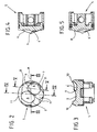
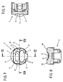
- FIGS. 1 and 6 equipped two side-by-side inlet valves 1 per cylinder. These inlet valves 1 are not located on one half of one shown cylinder and two side-by-side outlet valves 2 are on the other half of the cylinder.
- the Internal combustion engine has a spark plug 3, which is concentric to the axis of the cylinder is arranged.
- FIGS. 1 and 6 also show one in the cylinder of FIG Internal combustion engine arranged pistons 5 with two combustion chamber troughs 6, 6 'according to a first and a second embodiment.
- the fresh air flowing into the cylinder through the two inlet valves 1 forms a tumble flow within the combustion chamber. Training the tumble flow is favored when the two inlet valves 1 have a maximum distance from each other and one in the closed position have a minimum distance to the axis of the crankshaft.
- the inlet valves 1 and the outlet valves 2 are closed the spark plug 3 or arranged inclined to the axis of the cylinder.
- the injection valve 4 of the internal combustion engine is also on the axis of the cylinder arranged inclined, the angle of inclination a about 30 to 75 degrees is.
- the injector 4 provided with a bend angle that the injection jet E by about 15 degrees deflects so that the injection jet E depending on the operating state and crankshaft angle into the prevailing flow or into the second combustion chamber trough 6 'is directed.
- the injector comes 4, however, without a bend angle.
- the first embodiment in Figures 1 to 5 are the two combustion chamber troughs 6, 6 'to the center line M. of the piston 5 arranged offset.
- the first combustion chamber trough 6 is also somewhat smaller and less there deep as the second combustion chamber trough 6 '.
- the boundary wall 7 is the first combustion chamber trough 6 steeply rising to the side of the injection valves 1 and to Side of the exhaust valves 2 formed gently tapering, while the boundary wall 7 of the second combustion chamber trough 6 'to the side of the intake valves 1 gently tapering and rising steeply to the side of the exhaust valves 2 is trained.
- the boundary walls 7 formed in this way are special well suited for the tumble-like fresh air flow upwards redirected and the fuel injected into the second combustion chamber recess 6 ' can be.
- the deflection of the tumble flow is also supported through one or two ramps 8 next to the first combustion chamber trough 6, which the steeply rising boundary wall 7 of the second combustion bowl 6 ' are arranged adjacent.
- the two combustion chamber troughs 6, 6 ' are essentially straight by means of one Web 9 separated from each other. According to a further development, this web 9 can in the area below the spark plug 3 with one of the two combustion chamber troughs 6, 6 'connecting breakthrough. This breakthrough creates an additional space below the spark plug 3 for one stronger mixing of the gas mixtures and / or a safe ignition.
- pistons 5 according to the first and the second embodiment of the invention each formed roof-shaped, the ridge 10 in runs essentially along the center line M of the piston 5, which at the same time the dividing line between the inlet side and the outlet side of the piston 5.
- the piston 5 still has some squeezing surfaces 11 that are outside of the two combustion chamber troughs 6, 6 'are arranged.
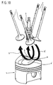
- FIGS. 10 and 11 are used to explain the method for mixture preparation the arrangement again for an internal combustion engine of gas exchange valves 1, 2, spark plug 3 and piston 5 of an internal combustion engine shown in Figure 1 and 6.
- the fuel is counter to the two flow branches S, S ', below the second flow branch S' ( Figure 10) or below the two flow branches S, S '( Figure 11) in the second combustion chamber bowl 6 'of the piston 5 is injected.
Abstract
Description
Die vorliegende Erfindung betrifft eine Brennkraftmaschine, die pro Zylinder zwei nebeneinander angeordnete Einlaßventile, wenigstens ein Auslaßventil, eine im wesentlichen koaxiale Zündkerze, ein Einspritzventil und einen Kolben pro Zylinder aufweist. Ferner betrifft die vorliegende Erfindung ein Verfahren zur Gemischaufbereitung bei einer Brennkraftmaschine.The present invention relates to an internal combustion engine per cylinder two inlet valves arranged side by side, at least one outlet valve, a substantially coaxial spark plug, an injector and a piston per cylinder. The present invention further relates to a method for mixture preparation in an internal combustion engine.
Eine derartige Brennkraftmaschine ist beispielsweise aus der Druckschrift US 4,617,896 bekannt. Bei dieser Brennkraftmaschine sind innerhalb des Saugrohres mehrere Einlaßkanäle vorgesehen, welche den Einlaßventilen zugeordnet werden können, und sind innerhalb dieser Einlaßkanäle zum Teil Drosselklappen vorgesehen. Der sich an das Saugrohr anschließende Zylinderkopf der Brennkraftmaschine weist dagegen einen den Einlaßventilen gemeinsamen Einlaßkanal auf, in den ein Einspritzventil mündet. Aufgrund der Gestaltung der Einlaßkanäle kann im gemeinsamen Einlaßkanal vor den Einlaßventilen eine gute Gemischverwirbelung stattfinden. Problematisch ist jedoch, daß dieses Gemisch nicht ohne erhebliche Strömungsverluste an den Einlaßventilen vorbei in den Brennraum der Brennkraftmaschine eingebracht werden kann. Zudem ist diese Ausführungsform für Brennkraftmaschinen mit Benzindirekteinspritzung kaum geeignet.Such an internal combustion engine is for example from the document US 4,617,896 known. In this internal combustion engine are within the Intake pipe provided several inlet channels, which are the inlet valves can be assigned, and are partly within these inlet channels Throttle valves provided. The cylinder head connected to the intake manifold the engine, however, has one of the intake valves common inlet channel into which an injection valve opens. Because of the design of the inlet channels can be in the common inlet channel before Intake valves a good mixture swirl take place. Is problematic however, that this mixture is not without significant flow losses introduced the inlet valves into the combustion chamber of the internal combustion engine can be. In addition, this embodiment is for internal combustion engines hardly suitable with direct petrol injection.
Ausgehend von diesem Stand der Technik ist es Aufgabe der vorliegenden Erfindung, eine Brennkraftmaschine zu konzipieren, welche eine bessere Gemischaufbereitung sowie einen sparsameren Betrieb ermöglicht. Ferner ist es Aufgabe der Erfindung ein Verfahren zur Gemischaufbereitung bei einer Brennkraftmaschine bereitzustellen.Based on this prior art, it is the task of the present Invention to design an internal combustion engine, which a better Mixture preparation and a more economical operation enables. Further it is an object of the invention to provide a method for mixture preparation in a Provide internal combustion engine.
Zur Lösung dieser Aufgabe weist die Brennkraftmaschine die Merkmale des
Patentanspruchs 1 auf. Demnach ist das Einspritzventil zwischen den zwei
Einlaßventilen und dem an die beiden Einlaßventile angrenzenden Abschnitt
der Zylinderwand angeordnet und weist der Kolben eine erste und eine
zweite Brennraummulde auf, wobei die erste und die zweite Brennraummulde
zu dem Einspritzventil jeweils unterschiedlich beabstandet angeordnet
sind. Durch die Anordnung des Einspritzventils arbeitet die Brennkraftmaschine
als Direkteinspritzer, wodurch das Gemisch erst im Brennraum aufbereitet
wird. Dabei wird eine verbesserte Gemischaufbereitung erhalten, indem
der im Zylinder hin- und hergehende Kolben in Abstimmung zu den vorhergehenden
Merkmalen der Erfindung eine erste und eine zweite Brennraummulde
aufweist, wobei die erste und die zweite Brennraummulde zu
dem Einspritzventil jeweils unterschiedlich beabstandet angeordnet sind.
Denn dadurch wird erreicht, daß die tumbleförmig in den Brennraum einströmende
Frischluft, welche durch die von den Einlaßventilen beherrschten
Einlaßöffnungen eintritt und an der den Einlaßventilen gegenüberliegenden
Zylinderwand entlang nach unten in Richtung auf den Kolben zu strömt, sowie
der je nach Betriebszustand der Brennkraftmaschine früher oder später
eingespritzte Kraftstoff mit der Frischluft homogen durchmischt oder aber als
geschichtete Ladung aufbereitet, zur Zündkerze bewegt und dort gezündet
werden kann.To solve this problem, the internal combustion engine has the features of
Vorteilhaft ist bei der erfindungsgemäßen Brennkraftmaschine vorgesehen, daß die beiden Einlaßventile einen maximalen Abstand zueinander aufweisen. Zudem sollten die beiden Einlaßventile in Schließstellung einen minimalen Abstand zu der Achse der Kurbelwelle aufweisen. Diese beiden Merkmale begünstigen die Erzeugung der tumbleförmigen Frischluftströmung innerhalb des Brennraums.It is advantageously provided in the internal combustion engine according to the invention that that the two inlet valves are at a maximum distance from one another. In addition, the two inlet valves should have a minimum in the closed position Have a distance to the axis of the crankshaft. These two Features favor the generation of the tumble-shaped fresh air flow inside the combustion chamber.
Das Einspritzventil kann in einem Winkel von ca. 60 bis 80 Grad zur Achse des Zylinders geneigt angeordnet sein. Dadurch kann das zwischen den beiden Einlaßventilen sowie dem an die beiden Einlaßventile angrenzenden Abschnitt der Zylinderwand angeordnete Einspritzventil den zur Verfügung stehenden Bauraum in platzsparender Weise nutzen.The injection valve can be at an angle of approx. 60 to 80 degrees to the axis of the cylinder can be arranged inclined. This can be between the two Inlet valves and that adjacent to the two inlet valves Section of the cylinder wall arranged injection valve available use the available space in a space-saving manner.
Bevorzugt weist das Einspritzventil einen Bendwinkel auf, der den Einspritzstrahl ablenkt. Mit Hilfe dieses Bendwinkels wird die Richtung des Einspritzstrahls so eingestellt, daß der Einspritzstrahl für den homogenen Magerbetrieb bei einem ersten Kurbelwellenwinkelbereich in die Tumbleströmung erfolgt und für den geschichteten Betrieb bei einem zweiten Kurbelwellenwinkelbereich unterhalb der im Brennraum vorherrschenden Tumbleströmung in die zweite Brennraummulde erfolgt, wodurch in beiden Betriebsfällen eine möglichst optimale Gemischaufbereitung stattfindet. The injection valve preferably has a bend angle that defines the injection jet distracts. With the help of this bend angle, the direction of the injection jet set so that the injection jet for homogeneous lean operation at a first crankshaft angle range into the tumble flow and for stratified operation in a second crankshaft angle range below the tumble flow in the combustion chamber in the second combustion chamber trough takes place, whereby one in both operating cases optimal mixture preparation takes place.
Zweckmäßig spritzt das Einspritzventil für den homogenen Magerbetrieb während des Ansaugtaktes bei einem Kurbelwellenwinkel von ca. 440 bis 280 Grad, bevor der Kolben den oberen Totpunkt erreicht, Kraftstoff in den Zylinder ein. Denn auf diese Weise wird der Kraftstoff etwa mittig in die im Brennraum vorherrschende Frischluftströmung eingebracht, so daß der Kraftstoff und die Frischluft gut durchmischt werden können.The injection valve expediently sprays for homogeneous lean operation during the intake stroke at a crankshaft angle of approx. 440 to 280 degrees before the piston reaches top dead center, fuel into the Cylinder. Because in this way the fuel is approximately in the middle of the Prevailing fresh air flow introduced so that the Fuel and fresh air can be mixed well.
Und für den geschichteten Magerbetrieb spritzt das Einspritzventil während des Kompressionstaktes bei einem Kurbelwellenwinkel von ca. 120 bis 30 Grad, bevor der Kolben den oberen Totpunkt erreicht, Kraftstoff in die zweite Brennraummulde des Kolbens ein. Somit wird ein großer Teil des Kraftstoffs unterhalb der tumbleförmigen Frischluftströmung eingespritzt, von der Frischluftströmung mit nach oben gerissen und schließlich zur Zündkerze transportiert. Dabei dient die erste Brennraummulde zur Führung der tumbleförmigen Frischluftströmung, während die zweite Brennraummulde zur Stabilisierung der sich ausbildenden Schichtladung dient.And for stratified lean operation, the injection valve sprays during the compression stroke at a crankshaft angle of approx. 120 to 30 Degrees before the piston reaches top dead center, fuel into the second Combustion chamber bowl of the piston. So a large part of the fuel injected below the tumble-shaped fresh air flow, from the Fresh air flow torn up and finally to the spark plug transported. The first combustion bowl serves to guide the tumble-shaped Fresh air flow, while the second combustion chamber trough Stabilization of the stratified charge is formed.
Bevorzugt sind die beiden Brennraummulden des Kolbens jeweils länglich ausgebildet. Und besonders bevorzugt ist die erste der beiden Brennraummulden etwas kleiner und weniger tief ausgebildet als die zweite der beiden Brennraummulden. Denn durch dieses Merkmal wird begünstigt, daß im geschichteten Magerbetrieb der Kraftstoff unterhalb der tumbleförmigen Frischluftströmung in die zweite der beiden Brennraummulden eingespritzt werden kann.The two combustion chamber troughs of the piston are each preferably elongated educated. And the first of the two combustion chamber troughs is particularly preferred somewhat smaller and less deep than the second of the two Firebox troughs. Because this characteristic favors that in the stratified Lean operation of the fuel below the tumble-shaped Fresh air flow injected into the second of the two combustion chamber troughs can be.
Die Begrenzungswand der ersten Brennraummulde kann zur Seite der Einlaßventile hin steil ansteigend und zur Seite der Auslaßventile hin sanft auslaufend ausgebildet sein, während die Begrenzungswand der zweiten Brennraummulde zur Seite der Einlaßventile hin sanft auslaufend und zur Seite der Auslaßventile hin steil ansteigend ausgebildet ist. Durch die sanft auslaufenden Begrenzungswände wird das Einlaufen der tumbleförmigen Frischluftströmung in die erste Brennraummulde bzw. das Einspritzen des kegelförmigen Kraftstoffstrahls in die zweite Brennraummulde erleichtert. Und durch die steil ansteigenden Begrenzungswände wird im weiteren Verlauf der Gemischaufbereitung die Durchmischung der Frischluft und des Kraftstoffs unterstützt.The boundary wall of the first combustion bowl can to the side of the intake valves rising steeply and gently tapering to the side of the exhaust valves be formed while the boundary wall of the second combustion chamber trough gently draining to the side of the inlet valves and to the side of the Exhaust valves is designed to rise steeply. Through the gently draining Boundary walls become the entry of the tumble-shaped fresh air flow into the first combustion chamber trough or the injection of the conical Fuel jet in the second combustion chamber recess facilitated. And through that The steeply rising boundary walls become in the further course of the mixture preparation supports the mixing of fresh air and fuel.
Die Brennraummulden können mittels eines im wesentlichen geraden Stegs voneinander getrennt sein. Die Abmessungen des Stegs bestimmen dabei, wie stark die tumbleförmige Frischluftströmung und der kegelförmige Einspritzstrahl im homogenen Magerbetrieb durchmischt werden oder im geschichteten Magerbetrieb gegeneinander stabilisiert werden.The combustion chamber troughs can be made by means of an essentially straight web be separated from each other. The dimensions of the web determine how strong the tumble-shaped fresh air flow and the conical injection jet be mixed in homogeneous lean operation or in stratified Lean operation can be stabilized against each other.
In einer ersten Ausführungsform ist der Steg zur Mittellinie des Kolbens schräg angeordnet und in einer zweiten Ausführungsform ist der Steg zur Mittellinie des Kolbens parallel angeordnet.In a first embodiment, the web is to the center line of the piston arranged obliquely and in a second embodiment, the web is for Center line of the piston arranged in parallel.
Gemäß einer Weiterbildung der Erfindung kann der Steg im Bereich unterhalb der Zündkerze mit einem die beiden Brennraummulden verbindenden Durchbruch versehen sein. Dieser Durchbruch schafft einen zusätzlichen Raum für eine noch stärkere Durchmischung von fettem und magerem Gasgemisch und gewährleistet eine sichere Entflammung. Es hat sich dabei bewährt, wenn der Durchbruch die Höhe des Stegs auf wenigstens die Hälfte reduziert und die Länge des Stegs um ca. 8-20 % des Kolbendurchmessers verringert.According to a development of the invention, the web can be in the area below the spark plug with one connecting the two combustion chamber troughs Breakthrough. This breakthrough creates an additional one Space for an even stronger mixing of rich and lean gas mixture and ensures a safe ignition. It has proven itself if the breakthrough the height of the web to at least half reduced and the length of the web by about 8-20% of the piston diameter decreased.
Vorteilhaft sollte der Kolben aufgrund der zueinander geneigt angeordneten Einlaß- und Auslaßventile dachförmig ausgebildet sein, wobei der Dachfirst im wesentlichen entlang der Mittellinie des Kolbens verlaufen sollte. Durch diese Ausgestaltung des Kolbens ist eine Brennraumform geschaffen, die ausreichend Möglichkeiten für Quetschflächen bietet und ein hohes Verdichtungsverhältnis sicherstellt.The piston should be advantageous due to the inclination to each other Inlet and outlet valves may be roof-shaped, the roof ridge should run substantially along the center line of the piston. By this configuration of the piston creates a combustion chamber shape that offers sufficient possibilities for crushing areas and a high compression ratio ensures.
Gelöst wird die Aufgabe der vorliegenden Erfindung ferner durch ein Verfahren zur Gemischaufbereitung bei einer Brennkraftmaschine gemäß Patentanspruch 17, indem innerhalb der Zylinder eine komplexe Luftströmung erzeugt wird, die als ein in zwei Strömungszweige aufgeteilter Doppeltumble ausgebildet ist. Mittels dieser beiden Strömungszweige wird die Gemischaufbereitung und damit der Wirkungsgrad der Brennkraftmaschine ganz erheblich verbessert.The object of the present invention is further achieved by a method for mixture preparation in an internal combustion engine according to claim 17 by creating a complex air flow within the cylinders which is divided into two flow branches is trained. The mixture preparation is carried out by means of these two flow branches and thus the efficiency of the internal combustion engine improved considerably.
Bevorzugt schließen die Achsen der beiden tumbleförmigen Strömungszweige des Doppeltumbles zusammen einen Winkel von ca. 0 bis +/- 45 Grad ein.The axes of the two tumble-shaped flow branches preferably close of the double surround together at an angle of approx. 0 to +/- 45 degrees on.
Für den homogenen Magerbetrieb der Brennkraftmaschine wird Kraftstoff entgegen die beiden Strömungszweige eingespritzt und für einen geschichteten Magerbetrieb wird Kraftstoff unterhalb eines der beiden Strömungszweige oder unterhalb die beiden Strömungszweige in die zweite Brennraummulde eingespritzt. Somit wird der eingespritzte Kraftstoff beim homogenen Magerbetrieb innerhalb des Brennraums gut verteilt und beim geschichteten Magerbetrieb als stabilisierte Gemischwolke zur Zündkerze transportiert, wo er dann entzündet werden kann.Fuel is used for the homogeneous lean operation of the internal combustion engine injected against the two flow branches and stratified for one Lean operation becomes fuel below one of the two flow branches or below the two flow branches in the second combustion chamber trough injected. Thus the injected fuel becomes homogeneous Lean operation well distributed within the combustion chamber and in the stratified Lean operation as a stabilized mixture cloud to the spark plug transported where it can then be ignited.
Die vorliegende Erfindung wird anhand der nachfolgenden Zeichnungsfiguren näher erläutert. Es zeigen:
Figur 1- Eine perspektivische Ansicht der Anordnung von Gaswechselventilen, Zündkerze, Einspritzventil und Kolben einer Brennkraftmaschine gemäß einer ersten Ausführungsform, in vereinfachter Darstellung;
Figur 2- eine Draufsicht des Kolbens aus
Figur 1; Figur 3- eine entlang der Linie III-III geschnittene Ansicht des Kolbens
aus
Figur 2; - Figur 4
- eine entlang der Linie IV-IV geschnittene Ansicht des Kolbens
aus
Figur 2; Figur 5- eine entlang der Linie V-V geschnittene Ansicht des Kolbens
aus
Figur 2; Figur 6- eine perspektivische Ansicht der Anordnung von Gaswechselventilen, Zündkerze, Einspritzventil und Kolben einer Brennkraftmaschine gemäß einer zweiten Ausführungsform, in vereinfachter Darstellung;
Figur 7- eine Draufsicht des Kolbens aus
Figur 6; Figur 8- eine entlang der Linie VIII-VIII geschnittene Ansicht des Kolbens
aus
Figur 7; Figur 9- eine entlang der Linie lX-lX geschnittene Ansicht des Kolbens
aus
Figur 7; Figur 10- eine perspektivische Ansicht der um 90 Grad gedrehten
Anordnung aus Figur 1, jedoch ohne Einspritzventil und mit einer pfeilartigen Darstellung der komplexen Luftströmung; und Figur 11- eine perspektivische Ansicht der Anordnung aus Figur 6, jedoch ohne Einspritzventil und mit einer pfeilartigen Darstellung der komplexen Luftströmung.
- Figure 1
- A perspective view of the arrangement of gas exchange valves, spark plug, injection valve and piston of an internal combustion engine according to a first embodiment, in a simplified representation;
- Figure 2
- a plan view of the piston of Figure 1;
- Figure 3
- a view along the line III-III of the piston of Figure 2;
- Figure 4
- a view taken along the line IV-IV of the piston of Figure 2;
- Figure 5
- a view along the line VV of the piston of Figure 2;
- Figure 6
- a perspective view of the arrangement of gas exchange valves, spark plug, injection valve and piston of an internal combustion engine according to a second embodiment, in a simplified representation;
- Figure 7
- a plan view of the piston of Figure 6;
- Figure 8
- a sectional view taken along the line VIII-VIII of the piston of Figure 7;
- Figure 9
- a view of the piston of Figure 7 cut along the line lX-lX;
- Figure 10
- 2 shows a perspective view of the arrangement from FIG. 1 rotated by 90 degrees, but without an injection valve and with an arrow-like representation of the complex air flow; and
- Figure 11
- a perspective view of the arrangement of Figure 6, but without an injection valve and with an arrow-like representation of the complex air flow.
Die erfindungsgemäße Brennkraftmaschine ist in den Figuren 1 und 6 mit
zwei nebeneinander angeordneten Einlaßventilen 1 pro Zylinder ausgestattet.
Diese Einlaßventile 1 befinden sich auf einer Halbseite eines nicht näher
dargestellten Zylinders und zwei nebeneinander angeordnete Auslaßventile
2 befinden sich auf der anderen Halbseite des Zylinders. Zudem weist die
Brennkraftmaschine eine Zündkerze 3 auf, die konzentrisch zu der Achse
des Zylinders angeordnet ist. Pro Zylinder ist außerdem ein Einspritzventil 4
vorgesehen, welches zwischen den beiden Einlaßventilen 1 und dem an die
beiden Einlaßventile 1 angrenzenden Abschnitt der Zylinderwand angeordnet
ist. Schließlich zeigen die Figuren 1 und 6 auch einen im Zylinder der
Brennkraftmaschine angeordneten Kolben 5 mit zwei Brennraummulden 6,
6' gemäß einer ersten und einer zweiten Ausführungsform.The internal combustion engine according to the invention is shown in FIGS. 1 and 6
equipped two side-by-
Die durch die beiden Einlaßventile 1 in den Zylinder einströmende Frischluft
bildet innerhalb des Brennraums eine Tumbleströmung aus. Die Ausbildung
der Tumbleströmung wird dabei begünstigt, wenn die beiden Einlaßventile 1
einen maximalen Abstand zueinander aufweisen und in Schließstellung einen
minimalen Abstand zu der Achse der Kurbelwelle aufweisen.The fresh air flowing into the cylinder through the two
In den Figuren 1 und 6 sind die Einlaßventile 1 sowie die Auslaßventile 2 zu
der Zündkerze 3 bzw. zu der Achse des Zylinders jeweils geneigt angeordnet.In FIGS. 1 and 6, the
Auch das Einspritzventil 4 der Brennkraftmaschine ist zu der Achse des Zylinders geneigt angeordnet, wobei der Neigungswinkel a ca. 30 bis 75 Grad beträgt. Bei der ersten Ausführungsform der Erfindung ist das Einspritzventil 4 mit einem Bendwinkel versehen, der den Einspritzstrahl E um ca. 15 Grad ablenkt, so daß der Einspritzstrahl E je nach Betriebszustand und Kurbelwellenwinkel in die vorherrschende Strömung bzw. in die zweite Brennraummulde 6' gerichtet ist. Bei der zweiten Ausführungsform kommt das Einspritzventil 4 dagegen ohne Bendwinkel aus.The injection valve 4 of the internal combustion engine is also on the axis of the cylinder arranged inclined, the angle of inclination a about 30 to 75 degrees is. In the first embodiment of the invention is the injector 4 provided with a bend angle that the injection jet E by about 15 degrees deflects so that the injection jet E depending on the operating state and crankshaft angle into the prevailing flow or into the second combustion chamber trough 6 'is directed. In the second embodiment, the injector comes 4, however, without a bend angle.
Um einen homogenen Magerbetrieb der Brennkraftmaschine zu realisieren,
wird durch das Einspritzventil 4 während des Ansaugtaktes bei einem Kurbelwellenwinkel
von ca. 440 bis 280 Grad, bevor der Kolben 5 den oberen
Totpunkt erreicht, Kraftstoff in die Frischluftströmung eingespritzt. Dadurch
verbleibt genügend Zeit für die Einspritzung einer ausreichenden Menge an
Kraftstoff sowie für eine homogene Durchmischung von Kraftstoff und
Frischluft.In order to achieve homogeneous lean operation of the internal combustion engine,
is through the injection valve 4 during the intake stroke at a crankshaft angle
from about 440 to 280 degrees before the
Um dagegen einen geschichteten Magerbetrieb der Brennkraftmaschine zu
realisieren, wird durch das Einspritzventil 4 während des Kompressionstaktes
bei einem Kurbelwellenwinkel von ca. 120 bis 30 Grad, bevor der Kolben
5 den oberen Totpunkt erreicht, Kraftstoff in die zweite Brennraummulde 6'
eingespritzt. Somit wird innerhalb des Brennraums eine geschichtete Gemischwolke
mit einem zündfähigen Anteil erzeugt. Die tumbleförmige
Frischluftströmung wird dabei in der ersten Brennraummulde 6 des Kolbens
5 zusammengeführt, während der eingespritzte Kraftstoff in der zweiten
Brennraummulde 6' gehalten bzw. stabilisiert wird und durch die weitere
Verdichtungsbewegung des Kolbens 5 in den Bereich unterhalb der Zündkerze
3 befördert wird, so daß der zündfähige Anteil der Gemischwolke von
einem Zündfunken der im Zylinder zentral angeordneten Zündkerze 3 erreichbar
ist.In order to achieve a stratified lean operation of the internal combustion engine
realize, is through the injection valve 4 during the compression stroke
at a crankshaft angle of about 120 to 30 degrees before the
Die Zentren der ersten und der zweiten Brennraummulde 6, 6' sind in beiden
Ausführungsformen der Erfindung jeweils unterschiedlich beabstandet zu
dem Einspritzventil 4 angeordnet. Gemäß der ersten Ausführungsform in
den Figuren 1 bis 5 sind die beiden Brennraummulden 6, 6' zur Mittellinie M
des Kolbens 5 versetzt angeordnet. Dabei sind die beiden Brennraummulden
6, 6' in der Projektion entlang der Achse des Zylinders jeweils leicht oval
ausgebildet, wobei die erste Brennraummulde 6 etwas kleiner und weniger
tief ist als die zweite Brennraummulde 6'. Und gemäß der zweiten Ausführungsform
in den Figuren 6 bis 9 sind die beiden Brennraummulden 6, 6' jeweils
seitlich neben der Mittellinie M des Kolbens 5 angeordnet, wobei deren
Längsachsen zur Mittellinie M des Kolbens 5 jeweils parallel angeordnet
sind. Auch dort ist die erste Brennraummulde 6 etwas kleiner und weniger
tief ausgebildet als die zweite Brennraummulde 6'. The centers of the first and
In beiden Ausführungsformen ist die Begrenzungswand 7 der ersten Brennraummulde
6 zur Seite der Einspritzventile 1 hin steil ansteigend und zur
Seite der Auslaßventile 2 hin sanft auslaufend ausgebildet, während die Begrenzungswand
7 der zweiten Brennraummulde 6' zur Seite der Einlaßventile
1 hin sanft auslaufend und zur Seite der Auslaßventile 2 hin steil ansteigend
ausgebildet ist. Die so ausgebildeten Begrenzungswände 7 sind besonders
gut geeignet, damit die tumbleartige Frischluftströmung nach oben
umgeleitet und der Kraftstoff in die zweite Brennraummulde 6' eingespritzt
werden kann. Unterstützt wird die Umlenkung der Tumbleströmung zudem
durch eine oder zwei Rampen 8 neben der ersten Brennraummulde 6, die an
die steil ansteigende Begrenzungswand 7 der zweiten Brennraummulde 6'
angrenzend angeordnet sind.In both embodiments, the
Die beiden Brennraummulden 6, 6' sind mittels eines im wesentlichen geraden
Stegs 9 voneinander getrennt. Dieser Steg 9 kann gemäß einer Weiterbildung
im Bereich unterhalb der Zündkerze 3 mit einem die beiden Brennraummulden
6, 6' verbindenden Durchbruch versehen sein. Dieser Durchbruch
schafft einen zusätzlichen Raum unterhalb der Zündkerze 3 für eine
stärkere Durchmischung der Gasgemische und/oder eine sichere Entflammung.The two
Ferner sind die Kolben 5 gemäß der ersten und der zweiten Ausführungsform
der Erfindung jeweils dachförmig ausgebildet, wobei der Dachfirst 10 im
wesentlichen entlang der Mittellinie M des Kolbens 5 verläuft, welche gleichzeitig
die Trennlinie zwischen der Einlaßseite und der Auslaßseite des Kolbens
5 darstellt.Furthermore, the
Schließlich weist der Kolben 5 noch einige Quetschflächen 11 auf, die außerhalb
der beiden Brennraummulden 6, 6' angeordnet sind.Finally, the
In den Figuren 10 und 11 sind zur Erläuterung des Verfahrens zur Gemischaufbereitung
bei einer Brennkraftmaschine nochmals die Anordnung
von Gaswechselventilen 1, 2, Zündkerze 3 und Kolben 5 einer Brennkraftmaschine
aus Figur 1 bzw. 6 dargestellt. Dabei ist die komplexe Luftströmung
als ein in zwei Strömungszweige S, S' aufgeteilter Doppeltumble ausgebildet.FIGS. 10 and 11 are used to explain the method for mixture preparation
the arrangement again for an internal combustion engine
of
Die beiden Strömungszweige S, S' treten jeweils durch eine der von den
beiden Einlaßventilen 1 beherrschten Einlaßöffnungen in den Brennraum
ein, werden an der den Einlaßventilen 1 gegenüberliegenden Zylinderwand
nach unten abgelenkt und setzen sich daraufhin in der ersten Brennraummulde
6 fort, wo sie schließlich nach oben hin umgelenkt werden. Dabei
schließen die Tumbleachse des ersten Strömungszweigs S und die Tumbleachse
des zweiten Strömungszweigs S' zusammen einen Winkel von ca. 20
Grad ein.The two flow branches S, S 'each pass through one of the
two
Je nachdem, ob die Brennkraftmaschine nun im homogenen Magerbetrieb
oder im geschichteten Magerbetrieb arbeitet, wird der Kraftstoff entgegen die
beiden Strömungszweige S, S', unterhalb den zweiten Strömungszweig S'
(Figur 10) oder unterhalb die beiden Strömungszweige S, S' (Figur 11) in die
zweite Brennraummulde 6' des Kolbens 5 eingespritzt.Depending on whether the internal combustion engine is now in homogeneous lean operation
or works in stratified lean operation, the fuel is counter to the
two flow branches S, S ', below the second flow branch S'
(Figure 10) or below the two flow branches S, S '(Figure 11) in the
second combustion chamber bowl 6 'of the
Claims (20)
dadurch gekennzeichnet, daß
characterized in that
Applications Claiming Priority (2)
| Application Number | Priority Date | Filing Date | Title |
|---|---|---|---|
| DE19801607A DE19801607A1 (en) | 1998-01-17 | 1998-01-17 | Internal combustion engine and mixture preparation method for an internal combustion engine |
| DE19801607 | 1998-01-17 |
Publications (3)
| Publication Number | Publication Date |
|---|---|
| EP0930427A2 true EP0930427A2 (en) | 1999-07-21 |
| EP0930427A3 EP0930427A3 (en) | 2000-04-05 |
| EP0930427B1 EP0930427B1 (en) | 2004-08-18 |
Family
ID=7854886
Family Applications (1)
| Application Number | Title | Priority Date | Filing Date |
|---|---|---|---|
| EP99100595A Expired - Lifetime EP0930427B1 (en) | 1998-01-17 | 1999-01-14 | Internal combustion engine and method for its mixture preparation |
Country Status (2)
| Country | Link |
|---|---|
| EP (1) | EP0930427B1 (en) |
| DE (2) | DE19801607A1 (en) |
Cited By (4)
| Publication number | Priority date | Publication date | Assignee | Title |
|---|---|---|---|---|
| EP1199462A3 (en) * | 2000-10-20 | 2003-04-23 | Yamaha Hatsudoki Kabushiki Kaisha | Internal combustion engine and piston for internal combustion engine |
| EP1288461A3 (en) * | 2001-08-24 | 2004-08-04 | Toyota Jidosha Kabushiki Kaisha | In-cylinder injection type spark-ignition internal combustion engine |
| FR2853353A1 (en) * | 2003-04-04 | 2004-10-08 | Peugeot Citroen Automobiles Sa | Internal combustion engine, has injection pump injecting petrol at specific pressure to injector, and injection pump and spark plug placed in cylinder head along respective axes forming specific angle |
| FR2861431A1 (en) * | 2003-10-24 | 2005-04-29 | Renault Sa | Piston for use in spark ignition engine, has hollow zone with two symmetrical portions extending parallel to axial plane and perpendicular to axis of symmetry to form two oblong half-cavities which extend from ignition control |
Families Citing this family (1)
| Publication number | Priority date | Publication date | Assignee | Title |
|---|---|---|---|---|
| DE102006044698B4 (en) * | 2006-09-22 | 2017-08-03 | Bayerische Motoren Werke Aktiengesellschaft | Combustion process for a spark-ignition internal combustion engine powered by direct fuel injection and supercharging |
Citations (1)
| Publication number | Priority date | Publication date | Assignee | Title |
|---|---|---|---|---|
| US4617896A (en) | 1985-03-14 | 1986-10-21 | Yamaha Hatsudoki Kabushiki Kaisha | Internal combustion engine having three intake valves per cylinder |
Family Cites Families (12)
| Publication number | Priority date | Publication date | Assignee | Title |
|---|---|---|---|---|
| JPS61138816A (en) * | 1984-12-07 | 1986-06-26 | Toyota Motor Corp | Fuel evaporation rate control system for direct-injection inernal-combustion engine |
| DE4020262A1 (en) * | 1990-06-26 | 1992-01-09 | Daimler Benz Ag | Combustion chamber for IC engine - is formed by depression in piston crown |
| JPH05179961A (en) * | 1991-12-27 | 1993-07-20 | Toyota Motor Corp | Intra-cylinder injection type internal combustion engine |
| DE4415073A1 (en) * | 1994-04-29 | 1995-11-02 | Fev Motorentech Gmbh & Co Kg | IC engine using alcohol-based fuel with spark ignition and direct fuel injection |
| DE69615130T2 (en) * | 1995-03-28 | 2002-06-13 | Mitsubishi Motors Corp | DIRECT INJECTION ENGINE |
| KR970703480A (en) * | 1995-03-28 | 1997-07-03 | 츠카하라 시게히사 | Internal injection type internal combustion engine |
| JP3681080B2 (en) * | 1996-02-09 | 2005-08-10 | 富士重工業株式会社 | Combustion chamber structure of in-cylinder direct injection spark ignition engine |
| DE19713030C2 (en) * | 1996-04-01 | 2000-02-24 | Avl List Gmbh | Four-stroke internal combustion engine with spark ignition |
| DE19713028C2 (en) * | 1996-04-01 | 2000-02-24 | Avl List Gmbh | Four-stroke internal combustion engine with spark ignition |
| DE19713029C2 (en) * | 1996-04-01 | 2000-02-24 | Avl List Gmbh | Four-stroke internal combustion engine with spark ignition |
| DE19638024A1 (en) * | 1996-09-18 | 1998-03-19 | Bosch Gmbh Robert | Internal combustion engine |
| DE19741380C2 (en) * | 1996-09-20 | 2000-12-28 | Fev Motorentech Gmbh | Reciprocating internal combustion engine with direct fuel injection via an injector arranged on the inlet side |
-
1998
- 1998-01-17 DE DE19801607A patent/DE19801607A1/en not_active Withdrawn
-
1999
- 1999-01-14 DE DE59910231T patent/DE59910231D1/en not_active Expired - Lifetime
- 1999-01-14 EP EP99100595A patent/EP0930427B1/en not_active Expired - Lifetime
Patent Citations (1)
| Publication number | Priority date | Publication date | Assignee | Title |
|---|---|---|---|---|
| US4617896A (en) | 1985-03-14 | 1986-10-21 | Yamaha Hatsudoki Kabushiki Kaisha | Internal combustion engine having three intake valves per cylinder |
Cited By (4)
| Publication number | Priority date | Publication date | Assignee | Title |
|---|---|---|---|---|
| EP1199462A3 (en) * | 2000-10-20 | 2003-04-23 | Yamaha Hatsudoki Kabushiki Kaisha | Internal combustion engine and piston for internal combustion engine |
| EP1288461A3 (en) * | 2001-08-24 | 2004-08-04 | Toyota Jidosha Kabushiki Kaisha | In-cylinder injection type spark-ignition internal combustion engine |
| FR2853353A1 (en) * | 2003-04-04 | 2004-10-08 | Peugeot Citroen Automobiles Sa | Internal combustion engine, has injection pump injecting petrol at specific pressure to injector, and injection pump and spark plug placed in cylinder head along respective axes forming specific angle |
| FR2861431A1 (en) * | 2003-10-24 | 2005-04-29 | Renault Sa | Piston for use in spark ignition engine, has hollow zone with two symmetrical portions extending parallel to axial plane and perpendicular to axis of symmetry to form two oblong half-cavities which extend from ignition control |
Also Published As
| Publication number | Publication date |
|---|---|
| DE59910231D1 (en) | 2004-09-23 |
| DE19801607A1 (en) | 1999-07-22 |
| EP0930427A3 (en) | 2000-04-05 |
| EP0930427B1 (en) | 2004-08-18 |
Similar Documents
| Publication | Publication Date | Title |
|---|---|---|
| DE3690387C2 (en) | Two=stroke vehicle engine control method | |
| DE19804161C2 (en) | Four-stroke internal combustion engine | |
| EP1060330B1 (en) | Internal combustion engine with direct fuel injection | |
| DE102004058244B4 (en) | Direct injection engine | |
| DE3016139A1 (en) | INSERT FOR FORMING A CHAMBER IN THE CYLINDER HEAD OF A DIESEL MACHINE | |
| DE19741380C2 (en) | Reciprocating internal combustion engine with direct fuel injection via an injector arranged on the inlet side | |
| DE3718083C2 (en) | ||
| EP0897052B1 (en) | Spark ignition internal combustion engine | |
| DE3808672A1 (en) | COMBUSTION ENGINE | |
| DE10354682B4 (en) | Reciprocating internal combustion engine with direct fuel injection via an injector arranged on the inlet side | |
| EP0930427B1 (en) | Internal combustion engine and method for its mixture preparation | |
| WO2001049996A1 (en) | Internal combustion piston engine with direct fuel injection by means of an injector that is arranged on the input side | |
| DE10354827A1 (en) | fuel injection system | |
| DE2508081C3 (en) | Internal combustion engine with main and additional combustion chamber | |
| DE19820085B4 (en) | Direct injection internal combustion engine | |
| DE2454813A1 (en) | Torch-ignited reciprocating internal combustion engine | |
| EP1135583B1 (en) | Direct injection internal combustion engine | |
| DE19730842A1 (en) | IC engine | |
| DE10323000B4 (en) | Method and piston-cylinder unit for generating a combustible fuel-gas mixture in a combustion chamber of a reciprocating internal combustion engine | |
| DE19753963A1 (en) | Internal combustion engine with direct fuel injection | |
| DE102004007408B4 (en) | Fuel injection device for an internal combustion engine | |
| WO2006048128A1 (en) | Combustion chamber of an internal combustion engine with direct injection | |
| DE102004053050A1 (en) | Internal combustion engine | |
| DE19809066A1 (en) | IC engine with direct fuel injection | |
| DE2417838C3 (en) | Spark ignition four-stroke internal combustion engine with a combustion chamber and a pocket-shaped additional space |
Legal Events
| Date | Code | Title | Description |
|---|---|---|---|
| PUAI | Public reference made under article 153(3) epc to a published international application that has entered the european phase |
Free format text: ORIGINAL CODE: 0009012 |
|
| AK | Designated contracting states |
Kind code of ref document: A2 Designated state(s): BE DE FR GB |
|
| AX | Request for extension of the european patent |
Free format text: AL;LT;LV;MK;RO;SI |
|
| PUAL | Search report despatched |
Free format text: ORIGINAL CODE: 0009013 |
|
| AK | Designated contracting states |
Kind code of ref document: A3 Designated state(s): AT BE CH CY DE DK ES FI FR GB GR IE IT LI LU MC NL PT SE |
|
| AX | Request for extension of the european patent |
Free format text: AL;LT;LV;MK;RO;SI |
|
| RIC1 | Information provided on ipc code assigned before grant |
Free format text: 7F 02F 1/42 A, 7F 02B 23/10 B, 7F 02B 31/08 B |
|
| 17P | Request for examination filed |
Effective date: 20000717 |
|
| AKX | Designation fees paid |
Free format text: BE DE FR GB |
|
| 17Q | First examination report despatched |
Effective date: 20030702 |
|
| GRAP | Despatch of communication of intention to grant a patent |
Free format text: ORIGINAL CODE: EPIDOSNIGR1 |
|
| GRAS | Grant fee paid |
Free format text: ORIGINAL CODE: EPIDOSNIGR3 |
|
| GRAA | (expected) grant |
Free format text: ORIGINAL CODE: 0009210 |
|
| AK | Designated contracting states |
Kind code of ref document: B1 Designated state(s): BE DE FR GB |
|
| REG | Reference to a national code |
Ref country code: GB Ref legal event code: FG4D Free format text: NOT ENGLISH |
|
| REF | Corresponds to: |
Ref document number: 59910231 Country of ref document: DE Date of ref document: 20040923 Kind code of ref document: P |
|
| GBT | Gb: translation of ep patent filed (gb section 77(6)(a)/1977) | ||
| PG25 | Lapsed in a contracting state [announced via postgrant information from national office to epo] |
Ref country code: BE Free format text: LAPSE BECAUSE OF NON-PAYMENT OF DUE FEES Effective date: 20050131 |
|
| ET | Fr: translation filed | ||
| PLBE | No opposition filed within time limit |
Free format text: ORIGINAL CODE: 0009261 |
|
| STAA | Information on the status of an ep patent application or granted ep patent |
Free format text: STATUS: NO OPPOSITION FILED WITHIN TIME LIMIT |
|
| BERE | Be: lapsed |
Owner name: AUDI A.G. Effective date: 20050131 |
|
| 26N | No opposition filed |
Effective date: 20050519 |
|
| PGFP | Annual fee paid to national office [announced via postgrant information from national office to epo] |
Ref country code: GB Payment date: 20070109 Year of fee payment: 9 |
|
| PGFP | Annual fee paid to national office [announced via postgrant information from national office to epo] |
Ref country code: DE Payment date: 20070131 Year of fee payment: 9 |
|
| PG25 | Lapsed in a contracting state [announced via postgrant information from national office to epo] |
Ref country code: DE Free format text: LAPSE BECAUSE OF THE APPLICANT RENOUNCES Effective date: 20070217 |
|
| BERE | Be: lapsed |
Owner name: *AUDI A.G. Effective date: 20050131 |
|
| PGFP | Annual fee paid to national office [announced via postgrant information from national office to epo] |
Ref country code: FR Payment date: 20070105 Year of fee payment: 9 |
|
| GBPC | Gb: european patent ceased through non-payment of renewal fee |
Effective date: 20080114 |
|
| REG | Reference to a national code |
Ref country code: FR Ref legal event code: ST Effective date: 20081029 |
|
| PG25 | Lapsed in a contracting state [announced via postgrant information from national office to epo] |
Ref country code: GB Free format text: LAPSE BECAUSE OF NON-PAYMENT OF DUE FEES Effective date: 20080114 |
|
| PG25 | Lapsed in a contracting state [announced via postgrant information from national office to epo] |
Ref country code: FR Free format text: LAPSE BECAUSE OF NON-PAYMENT OF DUE FEES Effective date: 20080131 |