EP0930211A1 - Bogie for a tiltable railway vehicle - Google Patents
Bogie for a tiltable railway vehicle Download PDFInfo
- Publication number
- EP0930211A1 EP0930211A1 EP99890003A EP99890003A EP0930211A1 EP 0930211 A1 EP0930211 A1 EP 0930211A1 EP 99890003 A EP99890003 A EP 99890003A EP 99890003 A EP99890003 A EP 99890003A EP 0930211 A1 EP0930211 A1 EP 0930211A1
- Authority
- EP
- European Patent Office
- Prior art keywords
- pendulum
- bogie according
- self
- web plates
- plates
- Prior art date
- Legal status (The legal status is an assumption and is not a legal conclusion. Google has not performed a legal analysis and makes no representation as to the accuracy of the status listed.)
- Granted
Links
Images


Classifications
-
- B—PERFORMING OPERATIONS; TRANSPORTING
- B61—RAILWAYS
- B61F—RAIL VEHICLE SUSPENSIONS, e.g. UNDERFRAMES, BOGIES OR ARRANGEMENTS OF WHEEL AXLES; RAIL VEHICLES FOR USE ON TRACKS OF DIFFERENT WIDTH; PREVENTING DERAILING OF RAIL VEHICLES; WHEEL GUARDS, OBSTRUCTION REMOVERS OR THE LIKE FOR RAIL VEHICLES
- B61F5/00—Constructional details of bogies; Connections between bogies and vehicle underframes; Arrangements or devices for adjusting or allowing self-adjustment of wheel axles or bogies when rounding curves
- B61F5/50—Other details
- B61F5/52—Bogie frames
-
- B—PERFORMING OPERATIONS; TRANSPORTING
- B61—RAILWAYS
- B61F—RAIL VEHICLE SUSPENSIONS, e.g. UNDERFRAMES, BOGIES OR ARRANGEMENTS OF WHEEL AXLES; RAIL VEHICLES FOR USE ON TRACKS OF DIFFERENT WIDTH; PREVENTING DERAILING OF RAIL VEHICLES; WHEEL GUARDS, OBSTRUCTION REMOVERS OR THE LIKE FOR RAIL VEHICLES
- B61F5/00—Constructional details of bogies; Connections between bogies and vehicle underframes; Arrangements or devices for adjusting or allowing self-adjustment of wheel axles or bogies when rounding curves
- B61F5/02—Arrangements permitting limited transverse relative movements between vehicle underframe or bolster and bogie; Connections between underframes and bogies
- B61F5/22—Guiding of the vehicle underframes with respect to the bogies
Definitions
- the invention relates to a bogie for a rail vehicle with a pendulum support with a central opening, articulated on the pendulum arms of a tilt mechanism are and attack pneumatic spring elements.
- the bogie can be designed with or without a travel drive. Because of of the tilt mechanism and that required for good driving characteristics multiple suspension it comes in the design of the individual assemblies for maximum space economy. But also low weight with sufficient rigidity and manufacturing economy should be aimed at.
- a generic bogie is known from EP-189 382 A2, in which a pendulum support is essentially cuboid Box formed with a central opening and by means of Pendulum arms is connected to another pendulum support.
- One the pendulum support can be tilted in the transverse direction, the other is connected to the axle beams via springs.
- the breakthrough takes up the tilt drive.
- bellows-shaped air springs At the two ends of the pendulum support attack bellows-shaped air springs, which are due to the load considerable air volume take up a lot of space.
- the box is relatively heavy and because of its cuboid shape and the downwardly projecting brackets for the articulation of the pendulum arms not trained for the load. The initiation of supporting forces creates special problems.
- the pendulum support is a tightly welded one closed box formed of a pressure vessel forms in the pendulum bearing tubes on both sides of the opening are tightly welded. So the box can do that for the air springs Take up the required air volume. The air springs then require much less installation space and can be placed over the box be connected without special lines.
- the one in itself rigid box is closed by the internal pressure and the welded pendulum bearing tubes further stiffened. Latter also ensure perfect force transmission.
- the box is preferably formed by: two outer and two inner ones extending the length of the box Web plates, two bulkhead plates, pressure belts and tension belts, whereby the two inner web plates and the two bulkhead plates limit the central opening and the self-aligning bearing tubes connect an inner and an outer web plate (Claim 2).
- the web plates designed in this way become a very high moment of resistance in the bending direction and simple manufacture achieved, the inner breakthrough means none Weakening of the pendulum support more.
- the bulkhead and the Self-aligning bearing tubes stiffen the web plates against bending twists.
- the tension belts between the inner and outer web plates welded and connect to the self-aligning bearing tubes (Claim 3). So they take over the suspension forces directly from the self-aligning bearing tubes, can adapt to the force curve be curved and the weld is easily accessible if the pressure belt is welded last. They also allow the web plates for a further increase in stiffness fish-bellied to train.
- cylindrical roller bearings brings a particularly high load capacity and protection of the bearing bolts, which is the case with the usual Plain bearings and pendulum arms composed of lamellas are very susceptible to wear. Installation is particularly easy, if the self-aligning bearing tube has a circumferential slot for the Passage of a pendulum arm (claim 7).
- a further improvement in the bearing of the pendulum arm is achieved one in that the outer rings of the cylindrical roller bearing grooves have, in which O-rings are inserted (claim 8).
- Such Bearings are standard parts, the grooves for receiving Circlips are determined.
- O-rings becomes a seal of the lubrication chamber and a relief assembly, especially if the outer rings are still in place the cylindrical roller bearing is mounted in the self-aligning bearing tube with a sliding seat are (claim 9).
- the O-rings serve as anti-rotation, a separate anti-rotation device is then due to the limited tilting movement is no longer necessary.
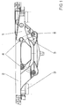
- Fig. 1 is a pendulum support with 1 and a traverse with 2 designated.
- the pendulum support 1 is supported by air springs 3 on the only indicated side members of a bogie frame from.
- Upper pendulum bearings 4 are provided on the pendulum support 1, in which pendulum arms 5 are pivotally mounted, the other End stored in lower self-aligning bearings 6 of the cross member 2 is. Due to the quadrilateral formed in this way, the one with the is not Carriage shown connected crossbar 2 tiltable.
- the traverse is partially torn off, so that on the right side of the pendulum support 1 is clearly visible.
- the pendulum support 1 is shown alone. It has a rectangular shape that can be seen in plan view (FIG. 3) Opening 10 for housing the tilt drive on. It forms a tightly welded area around the opening 10 closed box made of the following sheets is welded together: one inner web plate 11 and one outer Web plate 12 run the entire length of the pendulum support 1. According to the registered forces is theirs Outline fish-bellied.
- a first partition plate 13 and a second Bulkhead plate 14 connects the two inner web plates 11 and together with these form the opening 10.
- the Bulkhead plates 13, 14 are curved, they run vertically at first and approximately horizontal in its lower part.
- On the top are pressure belts 15 with the web plates 11, 12 and Bulkhead plates 13, 14 welded.
- the pressure belts 15 can have multiple more colliding sheets or a single sheet central opening 10 be.
- outer guide parts 21 sword-shaped brackets 22 for the attack of the not shown Tilt drive
- support plates 23 for the air springs 3 with a hole (not shown) for connecting it to the inside of the box 1 forming a pressure vessel
- two guide boxes 25 One is on each side outer web plate welded tight and thus forms one further pressure chamber, each with at least one hole 26 with the Pressure chamber in the interior of the pendulum carrier is connected.
- the inner web plates 11 point where they no longer have the opening Limit 10, cutouts 24 to reduce weight and around the spaces between the inner and outer web plates 11, 12 with the space between the inner web plates 11 to connect in terms of flow.
- FIG. 4 shows a section through the upper self-aligning bearing 4.
- Im Self-aligning bearing tube 19 is a bearing pin 30 by means of full complement Roller bearings stored.
- a inner roller bearing 31 and an outer roller bearing 32 are provided, both are, for example, double roller bearings of known design.
- the self-aligning bearing tube 19 with a circumferential groove 33 provided, the bottom in a leading out of the tube Slot 34 merges. Through this slot there are several interconnected slats existing pendulum arm 5 from the Pendulum bearing tube 19 led out.
- the bearings 31, 32 have circumferential grooves 35, which are normally can be used to hold circlips. Here but take up O-rings 36 which are essentially the same as those Seal the lubrication holes 37 and the spaces formed around them. In addition, they provide adequate anti-twist protection the bearing outer rings opposite the self-aligning bearing tube 19, if they are fitted with a sliding seat. Finally there is an inner washer 38 and a bearing pin 30 with a collar 39 provided that clamped together by means of a threaded bolt 40 become. In this way, the pendulum arm 5 between the Inner rings of the inner and outer roller bearings 31, 32 clamped. Since it is in the circumferential groove 33 and in the slot 34 is guided laterally, is an axial fixing of the bearing pin 30 not required.
- This arrangement is clean and low-wear and allows besides a simple assembly: after inserting the inner pane 38 is first the inner roller bearing 31 in the self-aligning bearing tube 19 inserted, then the pendulum arm 5 through the slot 34th inserted and inserted in the sequence of the bearing pin 30. Only then is the outer roller bearing 32 inserted and by means of the outer disc 39 clamped. This assembly is by the Fit sliding seat between the outer rings of the roller bearings 31,32 and the pendulum bearing tube much easier.
Landscapes
- Engineering & Computer Science (AREA)
- Mechanical Engineering (AREA)
- Bearings For Parts Moving Linearly (AREA)
Abstract
Description
Die Erfindung handelt von einem Drehgestell für ein Schienenfahrzeug mit einem einen mittigen Durchbruch aufweisenden Pendelträger, an dem Pendelarme eines Neigemechanismus angelenkt sind und pneumatische Federelemente angreifen. Ein solches Drehgestell kann mit oder ohne Fahrantrieb ausgeführt sein. Wegen des Neigemechanismus und der für gute Fahreigenschaften erforderlichen mehrfachen Federung kommt es bei der Gestaltung der einzelnen Baugruppen auf höchste Raumökonomie an. Aber auch geringes Gewicht bei ausreichender Steifigkeit und Fertigungsökonomie sind anzustreben.The invention relates to a bogie for a rail vehicle with a pendulum support with a central opening, articulated on the pendulum arms of a tilt mechanism are and attack pneumatic spring elements. Such one The bogie can be designed with or without a travel drive. Because of of the tilt mechanism and that required for good driving characteristics multiple suspension it comes in the design of the individual assemblies for maximum space economy. But also low weight with sufficient rigidity and manufacturing economy should be aimed at.
Aus der EP-189 382 A2 ist ein gattungsgemäßes Drehgestell bekannt, bei dem ein Pendelträger als im wesentlichen quaderförmiger Kasten mit mittigem Durchbruch ausgebildet und mittels Pendelarmen mit einem weiteren Pendelträger verbunden ist. Einer der Pendelträger ist in Querrichtung neigbar, der andere ist über Federn mit den Achsträgern verbunden. Der Durchbruch nimmt den Neigeantrieb auf. An den beiden Enden des Pendelträgers greifen balgförmige Luftfedern an, die wegen des lastbedingt erheblichen Luftvolumens sehr viel Bauraum beanspruchen. Der Kasten ist relativ schwer und wegen seiner Quaderform und den abwärts ragenden Konsolen für die Anlenkung der Pendelarme nicht belastungsgerecht ausgebildet. Die Einleitung der Stützkräfte bereitet dabei besondere Probleme. A generic bogie is known from EP-189 382 A2, in which a pendulum support is essentially cuboid Box formed with a central opening and by means of Pendulum arms is connected to another pendulum support. One the pendulum support can be tilted in the transverse direction, the other is connected to the axle beams via springs. The breakthrough takes up the tilt drive. At the two ends of the pendulum support attack bellows-shaped air springs, which are due to the load considerable air volume take up a lot of space. The box is relatively heavy and because of its cuboid shape and the downwardly projecting brackets for the articulation of the pendulum arms not trained for the load. The initiation of supporting forces creates special problems.
Es ist daher Ziel der Erfindung, den Pendelträger so zu gestalten, daß im gesamten Drehgestell höchste Raumökonomie erreicht wird, wobei er bei möglichst geringem Gewicht und einfacher Fertigung allen Kräften und Belastungen standhält.It is therefore the aim of the invention to design the pendulum support in such a way that maximum space economy is achieved in the entire bogie being, while being as light as possible and simpler Production withstands all forces and loads.
Erfindungsgemäß ist dazu der Pendelträger als dicht geschweißter geschlossener Kasten ausgebildet, der einen Druckbehälter bildet, in den beiderseits der Durchbrechung Pendellagerrohre dicht eingeschweißt sind. So kann der Kasten das für die Luftfedern erforderliche Luftvolumen aufnehmen. Die Luftfedern benötigen dann viel weniger Bauraum und können über den Kasten ohne besondere Leitungen verbunden sein. Der an sich schon steife geschlossene Kasten wird durch den Innendruck und die eingeschweißten Pendellagerrohre weiter versteift. Letztere sorgen zudem für eine einwandfreie Krafteinleitung.According to the invention, the pendulum support is a tightly welded one closed box formed of a pressure vessel forms in the pendulum bearing tubes on both sides of the opening are tightly welded. So the box can do that for the air springs Take up the required air volume. The air springs then require much less installation space and can be placed over the box be connected without special lines. The one in itself rigid box is closed by the internal pressure and the welded pendulum bearing tubes further stiffened. Latter also ensure perfect force transmission.
Vorzugsweise wird der Kasten gebildet von: zwei äusseren und zwei inneren sich über die Länge des Kastens erstreckenden Stegblechen, zwei Schottblechen, Druckgurten und Zuggurten, wobei die beiden inneren Stegbleche und die beiden Schottbleche den mittigen Durchbruch begrenzen und die Pendellagerrohre jeweils ein inneres und ein äusseres Stegblech verbinden (Anspruch 2). Durch die so ausgebildeten Stegbleche wird ein sehr hohes Widerstandmoment in Biegerichtung und einfache Fertigung erreicht, der innere Durchbruch bedeutet dadurch keine Schwächung des Pendelträgers mehr. Die Schottbleche und die Pendellagerrohre versteifen die Stegbleche gegen Biegedrillknicken.The box is preferably formed by: two outer and two inner ones extending the length of the box Web plates, two bulkhead plates, pressure belts and tension belts, whereby the two inner web plates and the two bulkhead plates limit the central opening and the self-aligning bearing tubes connect an inner and an outer web plate (Claim 2). The web plates designed in this way become a very high moment of resistance in the bending direction and simple manufacture achieved, the inner breakthrough means none Weakening of the pendulum support more. The bulkhead and the Self-aligning bearing tubes stiffen the web plates against bending twists.
In einer besonders vorteilhaften Ausführungsform der Erfindung sind die Zuggurten jeweils zwischen innerem und äusserem Stegblech angeschweißt und schließen an die Pendellagerrohre an (Anspruch 3). So übernehmen sie die Aufhängungskräfte direkt von den Pendellagerrohren, können dem Kraftverlauf entsprechend gebogen sein und die Schweißnaht ist leicht zugänglich, wenn der Druckgurt zuletzt geschweißt wird. Sie gestatten es nebstbei, die Stegbleche für weitere Erhöhung der Steifigkeit fischbauchförmig auszubilden.In a particularly advantageous embodiment of the invention are the tension belts between the inner and outer web plates welded and connect to the self-aligning bearing tubes (Claim 3). So they take over the suspension forces directly from the self-aligning bearing tubes, can adapt to the force curve be curved and the weld is easily accessible if the pressure belt is welded last. They also allow the web plates for a further increase in stiffness fish-bellied to train.
Zur weiteren Verringerung des Gewichtes ist es günstig, die beiden inneren Stegbleche dort, wo sie nicht die Durchbrechung bilden, mit Ausschnitten zu versehen (Anspruch 4). Ausserdem wird dadurch der Luftraum vor und hinter dem Durchbruch mit dem, zwischen den inneren und äusseren Stegblechen verbunden.To further reduce weight, it is convenient to two inner web plates where they do not have the opening form to provide with cutouts (claim 4). Furthermore the air space in front of and behind the breakthrough is connected between the inner and outer web plates.
Eine weitere Vergrößerung des Luftraumes, Erhöhung der Steifigkeit und Führung des Pendelträgers in Querrichtung wird dadurch erreicht, daß an den äusseren Stegblechen Führungskästen dicht angeschweißt sind, die Druckräume begrenzen, die durch Löcher in den äusseren Stegblechen mit dem Inneren des Kastens in Verbindung stehen (Anspruch 5).A further enlargement of the airspace, increasing the rigidity and guidance of the pendulum support in the transverse direction is thereby achieved that the outer web plates tight guide boxes are welded on, which delimit pressure chambers through holes in the outer web plates in connection with the inside of the box stand (claim 5).
In Weiterbildung der Erfindung kann in dem Pendellagerrohr ein Lagerbolzen für den Pendelarm mittels zweier Zylinderrollenlager gelagert sein, wobei der Pendelarm geschlossene Augen aufweist, mit denen er auf den Lagerbolzen zwischen den beiden Zylinderrollenlagern aufgefädelt ist (Anspruch 6). Dadurch wird das Pendellagerrohr symmetrisch und gleichmäßig belastet. Der Einsatz der Zylinderrollenlager bringt besonders hohe Tragfähigkeit und Schonung der Lagerbolzen, die bei den üblichen Gleitlagerungen und aus Lamellen zusammengesetzten Pendelarmen sehr verschleißanfällig sind. Die Montage wird besonders einfach, wenn das Pendellagerrohr einen Umfangsschlitz für den Durchtritt eines Pendelarmes aufweist (Anspruch 7).In a development of the invention, a can be in the self-aligning bearing tube Bearing pin for the pendulum arm using two cylindrical roller bearings be stored with the pendulum arm closed eyes, with which he is on the bearing pin between the two cylindrical roller bearings is threaded (claim 6). This will the pendulum bearing tube is loaded symmetrically and evenly. Of the The use of cylindrical roller bearings brings a particularly high load capacity and protection of the bearing bolts, which is the case with the usual Plain bearings and pendulum arms composed of lamellas are very susceptible to wear. Installation is particularly easy, if the self-aligning bearing tube has a circumferential slot for the Passage of a pendulum arm (claim 7).
Eine weitere Verbesserung der Lagerung des Pendelarmes erreicht man dadurch, daß die Aussenringe der Zylinderrollenlager Nuten aufweisen, in die O-Ringe eingelegt sind (Anspruch 8). Derartige Lager sind Normteile, wobei die Nuten für die Aufnahme von Sicherungsringen bestimmt sind. Durch Einlegen von O-Ringen wird eine Abdichtung des Schmierraumes und eine Erleichterung der Montage erreicht, vor allem wenn weiters die Aussenringe der Zylinderrollenlager im Pendellagerrohr mit Schiebesitz montiert sind (Anspruch 9). Weiters dienen die O-Ringe als Verdrehhemmung, eine eigene Verdrehsicherung ist dann wegen der begrenzten Neigebewegung nicht mehr nötig.A further improvement in the bearing of the pendulum arm is achieved one in that the outer rings of the cylindrical roller bearing grooves have, in which O-rings are inserted (claim 8). Such Bearings are standard parts, the grooves for receiving Circlips are determined. By inserting O-rings becomes a seal of the lubrication chamber and a relief assembly, especially if the outer rings are still in place the cylindrical roller bearing is mounted in the self-aligning bearing tube with a sliding seat are (claim 9). Furthermore, the O-rings serve as anti-rotation, a separate anti-rotation device is then due to the limited tilting movement is no longer necessary.
Im Folgenden wird die Erfindung anhand von Abbildungen eines Ausführungsbeispieles beschrieben und erläutert. Es stellen dar:
- Fig.1:
- Den erfindungsgemäßen Pendelträger im Zusammenwirken mit den Pendelarmen und der Traverse zur Aufnahme eines Wagenkastens, in Fahrtrichtung teils in Ansicht,
- Fig.2:
- Den erfindungsgemäßen Pendelträger in Seitenansicht,
- Fig.3:
- Den erfindungsgemäßen Pendelträger in Draufsicht, und
- Fig.4:
- Detailschnitt nach IV-IV in Fig.3, vergrößert.
- Fig.1:
- The pendulum carrier according to the invention in cooperation with the pendulum arms and the cross member for receiving a car body, partly in view in the direction of travel,
- Fig. 2:
- The pendulum support according to the invention in side view,
- Fig. 3:
- The pendulum carrier according to the invention in plan view, and
- Fig. 4:
- Detail section according to IV-IV in Fig.3, enlarged.
In Fig. 1 ist ein Pendelträger mit 1 und eine Traverse mit 2
bezeichnet. Der Pendelträger 1 stützt sich über Luftfedern 3
auf den nur mehr angedeuteten Längsträgern eines Drehgestellrahmens
ab. Am Pendelträger 1 sind obere Pendellager 4 vorgesehen,
in denen Pendelarme 5 schwenkbar gelagert sind, deren anderes
Ende in unteren Pendellagern 6 der Traverse 2 gelagert
ist. Durch das so gebildete Gelenkviereck ist die mit dem nicht
dargestellten Wagenkasten verbundene Traverse 2 neigbar. In
Fig. 1 ist die Traverse teilweise abgerissen, sodaß auf der
rechten Bildseite der Pendelträger 1 ganz sichtbar ist.In Fig. 1 is a pendulum support with 1 and a traverse with 2
designated. The
In den Figuren 2 und 3 ist der Pendelträger 1 alleine abgebildet.
Er weist eine in Draufsicht (Fig. 3) erkennbare rechteckige
Durchbrechung 10 für die Unterbringung des Neigeantriebes
auf. Er bildet um die Durchbrechung 10 herum einen dicht geschweißten
geschlossenen Kasten, der aus den folgenden Blechen
zusammengeschweißt ist: je ein inneres Stegblech 11 und ein äußeres
Stegblech 12 verlaufen über die gesamte Länge des Pendelträgers
1. Den eingetragenen Kräften entsprechend ist deren
Umriß fischbauchförmig. Ein erstes Schottblech 13 und ein zweites
Schottblech 14 verbinden die beiden inneren Stegbleche 11
und bilden so gemeinsam mit diesen die Durchbrechung 10. Die
Schottbleche 13,14 sind gebogen, sie verlaufen zuerst senkrecht
und in ihrem unteren Teil angenähert horizontal. Auf der Oberseite
sind Druckgurten 15 mit den Stegblechen 11,12 und den
Schottblechen 13,14 verschweißt. Die Druckgurten 15 können meh-,
rere aneinander stoßende Bleche oder ein einziges Blech mit
mittiger Durchbrechung 10 sein.In Figures 2 and 3, the
Jeweils zwischen innerem und äußerem Stegblech 11,12 sind zwei
Pendellagerrohre 19 eingeschweißt, die die oberen Pendellager 4
aufnehmen. Weiters sind zwischen inneren und äußeren Stegblechen
11,12 Zuggurten eingeschweißt, und zwar ein erster Zuggurt
16, der von außen bis an das Pendellagerrohr 19 herangeführt
und mit diesem verschweißt ist, ein zweiter Zuggurt 17 der von
einem Pendellagerrohr 19 zuerst abwärts, dann horizontal und
dann wieder aufwärts zum anderen Pendellagerrohr 19 geführt und
mit diesem verschweißt ist, und einem dritten Zuggurt 18 der
von dem anderen Pendellagerrohr 19 weiter nach außen führt. Mit
20 ist die Schweißnaht bezeichnet, mit der der Zuggurt 16 mit
dem Pendellagerrohr 19 verbunden ist. Die anderen Zuggurten
17,18 sind auf dieselbe Weise mit dem Pendellagerrohr 19 verschweißt.
Es ist zu erkennen, daß diese von unten bzw., wenn
die Druckgurten erst nachher aufgeschweißt werden, auch von
oben gut zugänglich und prüfbar ist.There are two between the inner and
Weitere Bauteile des Pendelträgers 1 sind äußere Führungsteile
21, schwertförmige Konsolen 22 für den Angriff des nicht dargestellten
Neigeantriebes, Aufstandsplatten 23 für die Luftfedern
3 mit einem nicht eingezeichneten Loch zu deren Verbindung mit
dem Inneren des einen Druckbehälter bildenden Kastens 1, und
zwei Führungskästen 25. Je ein solcher ist an jeder Seite am
äußeren Stegblech dicht angeschweißt und bildet somit einen
weiteren Druckraum, der über je mindestens ein Loch 26 mit dem
Druckraum im Inneren des Pendelträgers in Verbindung steht. Die
inneren Stegbleche 11 weisen dort, wo sie nicht mehr die Durchbrechung
10 begrenzen, Ausschnitte 24 auf, zur Gewichtsverringerung
und um die Räume zwischen den inneren und äußeren Stegblechen
11,12 mit dem Raum zwischen den inneren Stegblechen 11
strömungsmäßig zu verbinden.Other components of the
Figur 4 zeigt einen Schnitt durch das obere Pendellager 4. Im
Pendellagerrohr 19 ist ein Lagerbolzen 30 mittels vollrolliger
Rollenlager gelagert. Im gezeigten Ausführungsbeispiel ist ein
inneres Rollenlager 31 und ein äußeres Rollenlager 32 vorgesehen,
beide sind beispielsweise Doppelrollenlager bekannter Bauweise.
Weiters ist das Pendellagerrohr 19 mit einer Umfangsnut
33 versehen, die unten in einen aus dem Rohr herausführenden
Schlitz 34 übergeht. Durch diesen Schlitz ist der aus mehreren
miteinander verbundenen Lamellen bestehende Pendelarm 5 aus dem
Pendellagerrohr 19 herausgeführt.Figure 4 shows a section through the upper self-aligning
Die Lager 31, 32 weisen Umfangsnuten 35 auf, die normalerweise
für die Aufnahme von Sicherungsringen verwendet werden. Hier
aber nehmen sie O-Ringe 36 auf, die die im wesentlichen von den
Schmierbohrungen 37 und deren Umgebung gebildeten Räume abdichten.
Darüber hinaus bewirken sie eine ausreichende Verdrehsicherung
der Lageraußenringe gegenüber dem Pendellagerrohr 19,
wenn diese mit Schiebesitz eingepaßt sind. Schließlich ist noch
eine innere Scheibe 38 und ein Lagerbolzen 30 mit einem Bund 39
vorgesehen, die mittels eines Gewindebolzens 40 zusammengespannt
werden. Auf diese Weise ist der Pendelarm 5 zwischen den
Innenringen des inneren und des äußeren Rollenlagers 31,32
festgeklemmt. Da er in der Umfangsnut 33 und im Schlitz 34
seitlich geführt ist, ist eine achsiale Festlegung des Lagerbolzens
30 nicht erforderlich.The
Diese Anordnung ist sauber und verschleißarm und ermöglicht
nebstbei eine einfache Montage: nach Einlegen der Innenscheibe
38 wird zuerst das innere Rollenlager 31 in das Pendellagerrohr
19 eingesetzt, sodann wird der Pendelarm 5 durch den Schlitz 34
hineingesteckt und in der Folge der Lagerbolzen 30 eingeführt.
Dann erst wird das äußere Rollenlager 32 eingesetzt und mittels
der Außenscheibe 39 festgespannt. Diese Montage wird durch die
Passung Schiebesitz zwischen den Außenringen der Rollenlager
31,32 und dem Pendellagerrohr wesentlich erleichtert.This arrangement is clean and low-wear and allows
besides a simple assembly: after inserting the
Claims (9)
Priority Applications (1)
| Application Number | Priority Date | Filing Date | Title |
|---|---|---|---|
| AT99890003T ATE273823T1 (en) | 1998-01-16 | 1999-01-13 | BOGIE FOR A TILT RAIL VEHICLE |
Applications Claiming Priority (2)
| Application Number | Priority Date | Filing Date | Title |
|---|---|---|---|
| AT5598 | 1998-01-16 | ||
| AT0005598A AT406570B (en) | 1998-01-16 | 1998-01-16 | BOG FOR A TILTABLE RAIL VEHICLE |
Publications (2)
| Publication Number | Publication Date |
|---|---|
| EP0930211A1 true EP0930211A1 (en) | 1999-07-21 |
| EP0930211B1 EP0930211B1 (en) | 2004-08-18 |
Family
ID=3480342
Family Applications (1)
| Application Number | Title | Priority Date | Filing Date |
|---|---|---|---|
| EP99890003A Expired - Lifetime EP0930211B1 (en) | 1998-01-16 | 1999-01-13 | Bogie for a tiltable railway vehicle |
Country Status (3)
| Country | Link |
|---|---|
| EP (1) | EP0930211B1 (en) |
| AT (2) | AT406570B (en) |
| DE (1) | DE59910230D1 (en) |
Cited By (1)
| Publication number | Priority date | Publication date | Assignee | Title |
|---|---|---|---|---|
| WO2000024625A2 (en) * | 1998-10-23 | 2000-05-04 | Knorr-Bremse Systeme für Schienenfahrzeuge GmbH | Brake system for railway vehicles |
Citations (2)
| Publication number | Priority date | Publication date | Assignee | Title |
|---|---|---|---|---|
| EP0189382A2 (en) | 1985-01-18 | 1986-07-30 | FIAT FERROVIARIA SAVIGLIANO S.p.A. | High-speed railway vehicle with a variable-attitude body |
| US4753174A (en) * | 1987-07-29 | 1988-06-28 | Amsted Industries Incorporated | Railway vehicle bolster with integral and brake system car reservoir |
Family Cites Families (4)
| Publication number | Priority date | Publication date | Assignee | Title |
|---|---|---|---|---|
| CH632199A5 (en) * | 1978-09-04 | 1982-09-30 | Schweizerische Lokomotiv | RAIL VEHICLE. |
| JP2870603B2 (en) * | 1990-08-13 | 1999-03-17 | 川崎重工業株式会社 | Railway pendulum vehicle |
| JPH0773996B2 (en) * | 1991-08-05 | 1995-08-09 | 財団法人鉄道総合技術研究所 | Bogie frame for railway vehicles |
| IT1253908B (en) * | 1991-12-10 | 1995-08-31 | Firema Ricerche Srl | MULTI-FUNCTIONAL RAILWAY TROLLEY |
-
1998
- 1998-01-16 AT AT0005598A patent/AT406570B/en not_active IP Right Cessation
-
1999
- 1999-01-13 AT AT99890003T patent/ATE273823T1/en active
- 1999-01-13 DE DE59910230T patent/DE59910230D1/en not_active Expired - Lifetime
- 1999-01-13 EP EP99890003A patent/EP0930211B1/en not_active Expired - Lifetime
Patent Citations (2)
| Publication number | Priority date | Publication date | Assignee | Title |
|---|---|---|---|---|
| EP0189382A2 (en) | 1985-01-18 | 1986-07-30 | FIAT FERROVIARIA SAVIGLIANO S.p.A. | High-speed railway vehicle with a variable-attitude body |
| US4753174A (en) * | 1987-07-29 | 1988-06-28 | Amsted Industries Incorporated | Railway vehicle bolster with integral and brake system car reservoir |
Cited By (3)
| Publication number | Priority date | Publication date | Assignee | Title |
|---|---|---|---|---|
| WO2000024625A2 (en) * | 1998-10-23 | 2000-05-04 | Knorr-Bremse Systeme für Schienenfahrzeuge GmbH | Brake system for railway vehicles |
| WO2000024625A3 (en) * | 1998-10-23 | 2000-11-09 | Knorr Bremse Systeme | Brake system for railway vehicles |
| US6991301B2 (en) | 1998-10-23 | 2006-01-31 | Knorr-Bremse Systeme Fuer Schienenfahrzeuge Gmbh | Brake system for railway vehicles |
Also Published As
| Publication number | Publication date |
|---|---|
| EP0930211B1 (en) | 2004-08-18 |
| ATE273823T1 (en) | 2004-09-15 |
| AT406570B (en) | 2000-06-26 |
| DE59910230D1 (en) | 2004-09-23 |
| ATA5598A (en) | 1999-11-15 |
Similar Documents
| Publication | Publication Date | Title |
|---|---|---|
| DE3812431C2 (en) | ||
| DE69833376T2 (en) | REJUVEN CURVED LEAF SPRING FOR TRUCK HANGERS | |
| EP0963304B1 (en) | Rear wheel suspension of a motor vehicle | |
| WO1999033742A1 (en) | Cable elevator with a drive plate | |
| EP1428698A1 (en) | Axle suspension for rigid axles in vehicles | |
| DE3512213A1 (en) | LENGTH CARRIER SUPPORT FOR THE FRONT PANEL OF A SELF-SUPPORTING VEHICLE BODY | |
| DE10106495C2 (en) | heavy goods vehicle | |
| DE2929927C2 (en) | Rail vehicle | |
| WO2016045864A1 (en) | Chassis frame with spring cup | |
| EP1276653B1 (en) | Running gear for a rail vehicle | |
| WO1998038074A1 (en) | Lifting system for an air-suspended vehicle axle | |
| EP0930211A1 (en) | Bogie for a tiltable railway vehicle | |
| EP0940319A2 (en) | Chassis of a heavy utility vehicle | |
| DE19548437C1 (en) | Two-axle rail vehicle bogie | |
| AT408642B (en) | MOTOR VEHICLE, IN PARTICULAR RAILWAY HIGH-SPEED MOTOR VEHICLE | |
| CH620399A5 (en) | Support of a wagon body of a rail vehicle on a bogie | |
| AT405391B (en) | BOGE OF A RAIL VEHICLE AND METHOD FOR THE PRODUCTION THEREOF | |
| DE19620962C2 (en) | bogie | |
| DE19940986A1 (en) | Front of the vehicle with a water tank | |
| DE19733968A1 (en) | Crank axle for motor vehicles and trailers | |
| AT407138B (en) | Running gear with pressurized vessel | |
| EP0670258B1 (en) | Axle lift for pneumatically suspended vehicle axles | |
| AT410928B (en) | REAR BEARING OF THE TILTABLE CAB OF A FRONT HANDLEBLE TRUCK | |
| EP0371435A1 (en) | Running gear for railway vehicles | |
| DE4422109C2 (en) | Couplable undercarriage arrangement for supporting and transverse inclination of a car body |
Legal Events
| Date | Code | Title | Description |
|---|---|---|---|
| PUAI | Public reference made under article 153(3) epc to a published international application that has entered the european phase |
Free format text: ORIGINAL CODE: 0009012 |
|
| AK | Designated contracting states |
Kind code of ref document: A1 Designated state(s): AT CH DE DK FR GB LI |
|
| AX | Request for extension of the european patent |
Free format text: AL;LT;LV;MK;RO;SI |
|
| 17P | Request for examination filed |
Effective date: 19991202 |
|
| AKX | Designation fees paid |
Free format text: AT CH DE DK FR GB LI |
|
| 17Q | First examination report despatched |
Effective date: 20030328 |
|
| GRAP | Despatch of communication of intention to grant a patent |
Free format text: ORIGINAL CODE: EPIDOSNIGR1 |
|
| GRAS | Grant fee paid |
Free format text: ORIGINAL CODE: EPIDOSNIGR3 |
|
| GRAA | (expected) grant |
Free format text: ORIGINAL CODE: 0009210 |
|
| AK | Designated contracting states |
Kind code of ref document: B1 Designated state(s): AT CH DE DK FR GB LI |
|
| REG | Reference to a national code |
Ref country code: GB Ref legal event code: FG4D Free format text: NOT ENGLISH |
|
| RAP2 | Party data changed (patent owner data changed or rights of a patent transferred) |
Owner name: SIEMENS TRANSPORTATION SYSTEMS GMBH & CO. KG |
|
| REG | Reference to a national code |
Ref country code: CH Ref legal event code: EP |
|
| REF | Corresponds to: |
Ref document number: 59910230 Country of ref document: DE Date of ref document: 20040923 Kind code of ref document: P |
|
| PG25 | Lapsed in a contracting state [announced via postgrant information from national office to epo] |
Ref country code: DK Free format text: LAPSE BECAUSE OF FAILURE TO SUBMIT A TRANSLATION OF THE DESCRIPTION OR TO PAY THE FEE WITHIN THE PRESCRIBED TIME-LIMIT Effective date: 20041118 |
|
| GBT | Gb: translation of ep patent filed (gb section 77(6)(a)/1977) |
Effective date: 20041220 |
|
| PLBE | No opposition filed within time limit |
Free format text: ORIGINAL CODE: 0009261 |
|
| STAA | Information on the status of an ep patent application or granted ep patent |
Free format text: STATUS: NO OPPOSITION FILED WITHIN TIME LIMIT |
|
| ET | Fr: translation filed | ||
| 26N | No opposition filed |
Effective date: 20050519 |
|
| REG | Reference to a national code |
Ref country code: FR Ref legal event code: CJ Ref country code: FR Ref legal event code: CD Ref country code: FR Ref legal event code: CA |
|
| REG | Reference to a national code |
Ref country code: FR Ref legal event code: PLFP Year of fee payment: 18 |
|
| PGFP | Annual fee paid to national office [announced via postgrant information from national office to epo] |
Ref country code: DE Payment date: 20160321 Year of fee payment: 18 |
|
| PGFP | Annual fee paid to national office [announced via postgrant information from national office to epo] |
Ref country code: AT Payment date: 20151207 Year of fee payment: 18 Ref country code: GB Payment date: 20160111 Year of fee payment: 18 Ref country code: FR Payment date: 20160115 Year of fee payment: 18 |
|
| PGFP | Annual fee paid to national office [announced via postgrant information from national office to epo] |
Ref country code: CH Payment date: 20160404 Year of fee payment: 18 |
|
| REG | Reference to a national code |
Ref country code: DE Ref legal event code: R119 Ref document number: 59910230 Country of ref document: DE |
|
| REG | Reference to a national code |
Ref country code: CH Ref legal event code: PL |
|
| REG | Reference to a national code |
Ref country code: AT Ref legal event code: MM01 Ref document number: 273823 Country of ref document: AT Kind code of ref document: T Effective date: 20170113 |
|
| GBPC | Gb: european patent ceased through non-payment of renewal fee |
Effective date: 20170113 |
|
| REG | Reference to a national code |
Ref country code: FR Ref legal event code: ST Effective date: 20170929 |
|
| PG25 | Lapsed in a contracting state [announced via postgrant information from national office to epo] |
Ref country code: FR Free format text: LAPSE BECAUSE OF NON-PAYMENT OF DUE FEES Effective date: 20170131 Ref country code: LI Free format text: LAPSE BECAUSE OF NON-PAYMENT OF DUE FEES Effective date: 20170131 Ref country code: CH Free format text: LAPSE BECAUSE OF NON-PAYMENT OF DUE FEES Effective date: 20170131 Ref country code: AT Free format text: LAPSE BECAUSE OF NON-PAYMENT OF DUE FEES Effective date: 20170113 |
|
| PG25 | Lapsed in a contracting state [announced via postgrant information from national office to epo] |
Ref country code: DE Free format text: LAPSE BECAUSE OF NON-PAYMENT OF DUE FEES Effective date: 20170801 Ref country code: GB Free format text: LAPSE BECAUSE OF NON-PAYMENT OF DUE FEES Effective date: 20170113 |