EP0930185A1 - Air conditioning apparatus for vehicle - Google Patents
Air conditioning apparatus for vehicle Download PDFInfo
- Publication number
- EP0930185A1 EP0930185A1 EP97942219A EP97942219A EP0930185A1 EP 0930185 A1 EP0930185 A1 EP 0930185A1 EP 97942219 A EP97942219 A EP 97942219A EP 97942219 A EP97942219 A EP 97942219A EP 0930185 A1 EP0930185 A1 EP 0930185A1
- Authority
- EP
- European Patent Office
- Prior art keywords
- engine
- driving
- driving force
- compressor
- water
- Prior art date
- Legal status (The legal status is an assumption and is not a legal conclusion. Google has not performed a legal analysis and makes no representation as to the accuracy of the status listed.)
- Granted
Links
- 238000004378 air conditioning Methods 0.000 title description 23
- XLYOFNOQVPJJNP-UHFFFAOYSA-N water Substances O XLYOFNOQVPJJNP-UHFFFAOYSA-N 0.000 claims abstract description 100
- 238000005338 heat storage Methods 0.000 claims abstract description 98
- 239000003507 refrigerant Substances 0.000 claims abstract description 84
- 238000010438 heat treatment Methods 0.000 claims abstract description 78
- 238000001816 cooling Methods 0.000 claims abstract description 68
- 230000017525 heat dissipation Effects 0.000 claims description 16
- 239000000498 cooling water Substances 0.000 claims description 14
- 230000000694 effects Effects 0.000 abstract description 3
- 238000000034 method Methods 0.000 description 26
- 239000000446 fuel Substances 0.000 description 16
- 239000000463 material Substances 0.000 description 12
- 238000010586 diagram Methods 0.000 description 10
- 239000007858 starting material Substances 0.000 description 7
- 230000006866 deterioration Effects 0.000 description 6
- 230000007613 environmental effect Effects 0.000 description 6
- 230000005540 biological transmission Effects 0.000 description 5
- 238000007791 dehumidification Methods 0.000 description 4
- 230000002093 peripheral effect Effects 0.000 description 3
- 239000011810 insulating material Substances 0.000 description 2
- 239000003990 capacitor Substances 0.000 description 1
- 230000006835 compression Effects 0.000 description 1
- 238000007906 compression Methods 0.000 description 1
- 238000009833 condensation Methods 0.000 description 1
- 230000005494 condensation Effects 0.000 description 1
- 238000012790 confirmation Methods 0.000 description 1
- 238000002347 injection Methods 0.000 description 1
- 239000007924 injection Substances 0.000 description 1
- 230000005415 magnetization Effects 0.000 description 1
- 238000010248 power generation Methods 0.000 description 1
Images


Classifications
-
- B—PERFORMING OPERATIONS; TRANSPORTING
- B60—VEHICLES IN GENERAL
- B60H—ARRANGEMENTS OF HEATING, COOLING, VENTILATING OR OTHER AIR-TREATING DEVICES SPECIALLY ADAPTED FOR PASSENGER OR GOODS SPACES OF VEHICLES
- B60H1/00—Heating, cooling or ventilating [HVAC] devices
- B60H1/32—Cooling devices
- B60H1/3204—Cooling devices using compression
- B60H1/3222—Cooling devices using compression characterised by the compressor driving arrangements, e.g. clutches, transmissions or multiple drives
-
- B—PERFORMING OPERATIONS; TRANSPORTING
- B60—VEHICLES IN GENERAL
- B60H—ARRANGEMENTS OF HEATING, COOLING, VENTILATING OR OTHER AIR-TREATING DEVICES SPECIALLY ADAPTED FOR PASSENGER OR GOODS SPACES OF VEHICLES
- B60H1/00—Heating, cooling or ventilating [HVAC] devices
- B60H1/00492—Heating, cooling or ventilating [HVAC] devices comprising regenerative heating or cooling means, e.g. heat accumulators
-
- B—PERFORMING OPERATIONS; TRANSPORTING
- B60—VEHICLES IN GENERAL
- B60H—ARRANGEMENTS OF HEATING, COOLING, VENTILATING OR OTHER AIR-TREATING DEVICES SPECIALLY ADAPTED FOR PASSENGER OR GOODS SPACES OF VEHICLES
- B60H1/00—Heating, cooling or ventilating [HVAC] devices
- B60H1/32—Cooling devices
- B60H1/3204—Cooling devices using compression
- B60H1/3205—Control means therefor
- B60H1/3208—Vehicle drive related control of the compressor drive means, e.g. for fuel saving purposes
-
- F—MECHANICAL ENGINEERING; LIGHTING; HEATING; WEAPONS; BLASTING
- F02—COMBUSTION ENGINES; HOT-GAS OR COMBUSTION-PRODUCT ENGINE PLANTS
- F02B—INTERNAL-COMBUSTION PISTON ENGINES; COMBUSTION ENGINES IN GENERAL
- F02B63/00—Adaptations of engines for driving pumps, hand-held tools or electric generators; Portable combinations of engines with engine-driven devices
- F02B63/06—Adaptations of engines for driving pumps, hand-held tools or electric generators; Portable combinations of engines with engine-driven devices for pumps
-
- F—MECHANICAL ENGINEERING; LIGHTING; HEATING; WEAPONS; BLASTING
- F01—MACHINES OR ENGINES IN GENERAL; ENGINE PLANTS IN GENERAL; STEAM ENGINES
- F01P—COOLING OF MACHINES OR ENGINES IN GENERAL; COOLING OF INTERNAL-COMBUSTION ENGINES
- F01P11/00—Component parts, details, or accessories not provided for in, or of interest apart from, groups F01P1/00 - F01P9/00
- F01P11/14—Indicating devices; Other safety devices
- F01P2011/205—Indicating devices; Other safety devices using heat-accumulators
Definitions
- the present invention relates to an air conditioner for a vehicle, which is used in a vehicle having, as a power source for driving the vehicle, an engine or both an engine and an electric motor.
- a hybrid car has been proposed in which an electric motor which electrically produces driving force is provided in addition to an engine which produces driving force by combusting fuel such as gasoline.
- the electric motor is driven by electric power supplied from a battery, which has been previously charged or which is charged by power generated by the engine during traveling, so as to drive the hybrid car.
- JP-A Japanese Patent Application Laid-Open
- a motor used only for driving a compressor of an air conditioner becomes unnecessary, and the air conditioner can be operated without using the driving force of an electric motor or the electric power of a battery to operate the electric motor.
- an object of the present invention is to provide an air conditioner for a vehicle, which allows air conditioning by efficiently utilizing the driving force of an engine or the driving force of an engine and an electric motor without providing driving means used only for driving a compressor.
- the present invention is an air conditioner for a vehicle, which air conditions a vehicle interior by a refrigerating cycle formed to include a compressor and an evaporator, said air conditioner for a vehicle comprising a water cooling cycle which is formed by water refrigerant heat exchange means provided in the refrigerating cycle and cooling water which is supplied as a refrigerant, heat storage means for cooling in which one of water cooled by said water-refrigerant heat exchange means and cooling heat obtained from water is stored, and heat dissipation means for cooling which cools air to be blown out into the vehicle interior by water supplied as a refrigerant from said heat storage means for cooling.
- the present invention comprises a water heating cycle which is formed by heat storage means for heating in which one of water heated by an engine and heating heat obtained from water is stored, and heat dissipation means for heating, which heats air to be blown out into the vehicle interior by supplying, as a refrigerant, one of cooling water for the engine and water heated by heat stored in said heat storage means for heating so as to allow heating of the vehicle interior.
- cooling water heated by the engine at the time of being driven is stored in the heat storage means for heating.
- cooling water for the engine is used to heat air to be blown out into the vehicle interior.
- the cooling water during driving of the engine is supplied from the heat storage means for heating to the heat dissipation means for heating so as to allow heating of the air to be blown out into the vehicle interior.
- heating and cooling can be carried out according to a vehicle occupant's preference. Further, it is also possible to carry out heating for the vehicle interior while carrying out dehumidification, without operating the compressor.
- the present invention comprises: heat storage means which can be used as both the heat storage means for cooling and also as the heat storage means for heating; first circulating means which can circulate water which becomes a refrigerant between the engine and said heat dissipation means for heating; second circulating means which can circulate water which becomes a refrigerant between said water-refrigerant heat exchange means and said heat dissipation means for cooling; and circulating passage switching means which changes said heat storage means to said first circulating means and said second circulating means to allow circulation of the water by any one of said first circulating means and said second circulating means.
- the first and second circulating means each allowing circulation of water used as a refrigerant are switched, and cool storage or heat storage is carried out by a single heat storage means.
- water which becomes a refrigerant by the cool storage or the heat storage in the heat storage means is circulated to allow cooling or heating. Accordingly, reduction in the number of parts which are used for heating and cooling can be achieved.
- the determination as to whether the heat storage means is used as a heat source for heating or a heat source for cooling may be made in accordance with the operating state of the air conditioner or environmental conditions such as the outside air temperature, the vehicle-interior temperature, and the like. For example, when the cooling operation is carried out by the air conditioner, there is a high possibility of the cooling operation being continuously carried out. For this reason, the second circulating means may be switched to allow circulation of water so that the heat storage means is used as the heat source for cooling. Further, when the outside air temperature is low in the winter or the like, there is a high possibility the heating operation will be carried out, and therefore, the first circulating means may be used to allow the circulation of water, serving as a refrigerant, between the heat storage means and the first circulating means.
- the heat dissipation means for heating and the heat dissipation means for cooling may be used in common with each other.
- the circulating means needs to be switched between heating and cooling, and at the time of heat dissipation (heating or cooling), water serving as a refrigerant only needs to be supplied from the heat storage means to the heat dissipation means.
- heating or cooling can be carried out in accordance with the heat stored in the heat storage means. Accordingly, the structures of the water cooling cycle and the water heating cycle can be simplified.
- the present invention is an air conditioner for a vehicle, which is provided in a vehicle equipped with an engine and an electric motor and which air conditions a vehicle interior by a refrigerating cycle formed to include a compressor and an evaporator, said air conditioner for a vehicle comprising: driving shafts provided respectively in the engine and in the electric motor; an output shaft connected to said driving shafts of the engine and the electric motor and rotated synchronously with a driving source which is one of the engine and the electric motor; driving force transmitting means which connects a driving shaft of one of the engine and the electric motor and a driving shaft of the compressor so as to transmit a driving force of said output shaft to the compressor; and driving force switching means which switches a driving source of the driving force to be transmitted to the driving shaft of the compressor by said driving force transmitting means.
- the driving source of the compressor is switched by the driving force switching means to separate the driving shaft of the engine and the driving shaft of the compressor from each other, and the compressor is driven by the driving force of the electric motor.
- the driving force switching means to separate the driving shaft of the engine and the driving shaft of the compressor from each other, and the compressor is driven by the driving force of the electric motor.
- no load for rotating the driving shaft of the engine is applied to the electric motor, and therefore, the compressor can be driven by the driving force of the electric motor. It is not necessary to provide driving means used only for driving the compressor and also not necessary to start the engine to drive the compressor. Accordingly, consumption of fuel caused by driving the engine can be restrained.
- the present invention is characterized in that said driving force switching means is clutch means provided between the driving shafts of the engine and the electric motor and said output shaft.
- said driving force switching means is clutch means provided between the driving shafts of the engine and the electric motor and said output shaft.
- the present invention comprises: first driving force transmitting means, which is provided as said driving force transmitting means, for transmitting driving force from the driving shaft of the engine to the driving shaft of the compressor; second driving force transmitting means which transmits driving force from the driving shaft of the electric motor to the driving shaft of the compressor; and clutch means which is provided as said driving force switching means and separates one of said first driving force transmitting means and said second driving force transmitting means from the driving shaft of the compressor.
- the driving force switching means is provided at the side of the driving shaft of the compressor and the engine is driven, the driving force of the engine is transmitted by the first driving force transmitting means, and when the electric motor is driven, the driving force of the electric motor is transmitted by the second driving force transmitting means.
- the driving force switching means only a load for driving the compressor is applied to the driving force switching means, and as compared with the case in which the driving force switching means is provided in the output shaft, the capacity of the driving force switching means can be made extremely small.
- a clutch is used as the driving force switching means, a small-size and low-cost clutch can be obtained.
- the present invention is an air conditioner for a vehicle, which is provided in a vehicle equipped with an engine and an electric motor and which air conditions a vehicle interior by a refrigerating cycle formed to include a compressor and an evaporator
- said air conditioner for a vehicle comprising: driving shafts provided respectively in the engine and in the electric motor; an output shaft connected to said driving shafts of the engine and the electric motor and rotated synchronously with a driving source which is one of the engine and the electric motor; load reduction means for reducing the driving load of said output shaft which rotates integrally with the driving shaft of the engine when the electric motor is driven; and driving force transmitting means which connects said output shaft and the driving shaft of the compressor to transmit the driving force of said output shaft to the compressor.
- the driving load reduction means operates so as to, for example, open a valve which allows air supply and exhaust for a cylinder of the engine or open a throttle valve which opens and closes a passage of air to be supplied into the cylinder of the engine, compression of air within the cylinder of the engine or increase in air-intake resistance can be prevented, thereby allowing reduction of a load for rotating the driving shaft.
- the compressor can be driven by using the driving force of the electric motor.
- the present invention is an air conditioner for a hybrid car, which air conditions a vehicle interior by a refrigerating cycle formed to include a compressor and an evaporator
- said air conditioner for a hybrid car comprising: an auxiliary-machine motor which drives a plurality of auxiliary machines provided in the hybrid car; third driving force transmitting means which can transmit the driving force of the engine and the driving force of said auxiliary-machine motor to the plurality of auxiliary machines and also to the driving shaft of the compressor; driving force interrupting means which interrupts the driving shaft of the engine and said third driving force transmitting means; and control means which controls said driving force interrupting means and said auxiliary-machine motor in accordance with a state in which the engine is driven.
- the driving force of the engine is transmitted by the third driving force transmitting means to auxiliary machines including the compressor. Further, when the engine has been stopped, the driving shaft of the engine and the third driving force transmitting means are separated from each other by the driving force interrupting means and the compressor is driven by the driving force of the auxiliary-machine motor.
- the compressor when the engine is stopped, the compressor can be driven by the auxiliary-machine motor in the same way as in other auxiliary machines provided in the vehicle, and when the engine is being driven, the auxiliary machines including the compressor can be driven by the driving force of the engine.
- an electric motor provided as a driving source for a running operation may be used, or an electric motor provided as a driving source for driving various auxiliary machines including the compressor and the like may also be used. Further, in addition to the electric motor provided as the driving source for a running operation, an electric motor serving as a driving source of auxiliary machines may also be provided.
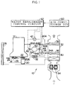
- FIG. 1 shows a schematic structure of an air conditioner for a vehicle (hereinafter referred to as "air conditioner 10") applied to a first embodiment.
- Fig. 2 schematically shows a portion of a hybrid car 12, which is an example of a vehicle equipped with the air conditioner 10.
- the hybrid car 12 equipped with the air conditioner 10 includes, as a power source for traveling, an electric motor 16 in addition to an engine 14.
- the electric motor 16 and the engine 14 are each connected to an output shaft 18 directly or indirectly.
- the output shaft 18 is connected to the electric motor 16 so that a driving shaft of the electric motor 16 becomes the output shaft 18, and a driving shaft 14A of the engine 14 is connected to the output shaft 18.
- the output shaft 18 is driven to rotate by the engine 14 or the electric motor 16.
- the electric motor 16 is driven by electric power supplied from, for example, a previously charged battery (not shown) mounted before traveling.
- the hybrid car 12 is provided with the compressor 20 disposed adjacent to the engine 14.
- a pulley 22 is mounted to a driving shaft 20A of the compressor 20 and an endless V belt 26 is entrained between the pulley 22 and a pulley 24 mounted to the driving shaft 14A of the engine 14.
- driving force is transmitted via the V belt 26 to the compressor 20.
- a refrigerating cycle is formed by a circulating passage of a refrigerant including the compressor 20, a capacitor 28, and an evaporator 30.
- a refrigerant liquefied by being compressed by the compressor 20 is supplied to the evaporator 30, and when the refrigerant is decompressed to be vaporized, air to be blown out into a vehicle interior is cooled.
- the pressure of the refrigerant supplied to the evaporator 30 is adjusted by controlling the capacity of the compressor 20. Further, water in the cooled air is applied to the evaporator 30 by dew condensation, and in the air conditioner 10, not only at the time of a cooling operation, but also at the time of a heating operation, a dehumidifying operation can be effected by operating the compressor 20 at a predetermined capacity.
- the evaporator 30 is provided within an air-conditioning duct 32.
- the air-conditioning duct 32 is provided with blower fans 34. Outside air or air within a vehicle interior is sucked into the air-conditioning duct 32 and is blown toward the evaporator 30, and the blown air is cooled by the evaporator 30 which is cooled by the circulating refrigerant, thereby allowing dehumidification.
- the air-conditioning duct 32 is provided with a heat-regenerative radiator (hereinafter referred to as "radiator 36") and a heater core 38, which are disposed adjacent to the evaporator 30. Air passing through the evaporator 30 further passes through the radiator 36 and the heater core 38 and is blown out from a blowout hole (not shown) into the vehicle interior.
- radiator 36 heat-regenerative radiator
- heater core 38 heater core
- a pair of hot-water pipes 40A and 40B are connected to the heater core 38 between the engine 14 and the heater core 38.
- An electrically operated pump 42 is provided at an intermediate portion of one hot-water pipe 40A. Driving the electrically operated pump 42 allows cooling water for the engine 14 to be supplied to the heater core 38.
- the heater core 38 heats air passing through the heater core 38 with the cooling water serving as a refrigerant (the cooling water will be hereinafter referred to as "water refrigerant").
- the other hot-water pipe 40B connected to the heater core 38 is branched off by a pair of branch pipes 44A and 44B.
- These branch pipes 44A, 44B are respectively provided with passage switching valves 46 and 48 in a pair.
- a heat storage tank 50 is connected to and between these passage switching valves 46 and 48. With the heat storage tank 50 communicating with the hot-water pipe 40B via the branch pipes 44A and 44B due to the operation of the passage switching valves 46 and 48, a water refrigerant circulated while being heated by the engine 14 is supplied to the heat storage tank 50.
- the heat storage tank 50 is filled with a heat accumulating material surrounded by a heat insulating material. With the water refrigerant circulated between the heat storage tank 50 and the engine 14 passing through the heat storage tank 50, the heat accumulating material is heated by the water refrigerant. The heat storage tank 50 is maintained with the temperature of the heat accumulating material being kept by the heat insulating material. Further, when, while the engine 14 is stopped, the electrically operated pump 42 is operated to allow the water refrigerant to be supplied to the heat core 38 to pass through the heat storage tank 50, the water refrigerant is heated due to heat exchange effected between the water refrigerant and the heat accumulating material. As a result, a water heating cycle is formed in which, even when the engine 14 is in a stopped state, air passing through the heater core 38 is heated to allow the vehicle interior to be heated.
- a water-refrigerant heat exchanger 52 is mounted between the evaporator 30 and the compressor 20, which form the refrigerating cycle.
- the water-refrigerant heat exchanger 52 is cooled in such a manner that a refrigerant passing through the evaporator 30 is supplied to the water-refrigerant heat exchanger 52 and is further decompressed.
- a pair of cold-water pipes 54A and 54B are connected to the radiator 36.
- One cold-water pipe 54B is connected to the water-refrigerant heat exchanger 52.
- the other cold-water pipe 54B is connected to the passage switching valve 48 and an electrically operated pump 56 is mounted at an intermediate portion of the other cold-water pipe 54B.
- the water-refrigerant heat exchanger 52 is connected to the passage switching valve 46 by a cold-water pipe 54C.
- the electrically operated pump 56 is operated to allow circulation of the water refrigerant, and the water refrigerant passes through the water-refrigerant heat exchanger 52, the cooled water refrigerant is supplied to the heat storage tank 50.
- the heat storage tank 50 allows the heat accumulating material to be cooled when the water refrigerant passes through the heat storage tank 50.
- the water refrigerant passing through the heat storage tank 50 is supplied to the radiator 36 by the operation of the electrically operated pump 56, the water refrigerant is cooled by the heat accumulating material within the heat storage tank 50.
- a water cooling cycle is formed in such a manner that the water refrigerant cooled in the heat storage tank 50 is supplied to the radiator 36 and air within the air-conditioning duct 32, passing through the radiator 36, is cooled.
- the air conditioner 10 includes an air-conditioner ECU 60 which controls air conditioning.
- the air-conditioner ECU 60 has a general structure in which, by controlling each operation of the compressor 20, the blower fans 34, and the like in accordance with an operating state of an unillustrated operation panel (setting of an operating condition) while detecting the outside air temperature, the indoor air temperature, and the like, air for a cooling/heating operation or a dehumidifying operation is blown out into the vehicle interior and the vehicle interior is thereby maintained in a desired air-conditioned state.
- an unillustrated operation panel setting of an operating condition
- the air conditioner 10 also includes a water-refrigerant control circuit 62.
- the water-refrigerant control circuit 62 is connected to the air-conditioner ECU 60 and also to an engine ECU (not shown) for controlling the engine 14. Further, the passage switching valves 46 and 48 and the electrically operated pumps 42 and 56 are each connected to the water-refrigerant control circuit 62.
- Signals corresponding to an operating state of the air conditioner 10 and environmental conditions such as the outside air temperature, the indoor air temperature, and the like are inputted from the air-conditioner ECU 60 to the water-refrigerant control circuit 62. Further, a signal which indicates an operating state of the engine 14 is inputted from the engine ECU.
- the water-refrigerant control circuit 62 controls the passage switching valves 46 and 48 and the electrically operated pumps 42 and 56 based on the various signals.
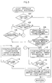
- the flow chart shown in Fig. 3 shows an example of heat storage processing for the heat storage tank 50.
- the first step 100 it is ascertained whether the engine 14 has been started (switched on), i.e., whether the hybrid car 12 is traveling using the engine 14.
- the process proceeds to step 102.
- step 102 it is ascertained whether the air conditioner 10 is switched on.
- step 104 in which it is ascertained whether the air conditioner 10 is operating in a cooling mode or a heating mode.
- step 106 environmental conditions such as the outside air temperature are measured.
- step 108 it is determined from the measured environmental conditions such as the outside air temperature whether the possibility is of the air conditioner 10 being operated in a cooling mode or in a heating mode. For example, in the summer period in which the outside air temperature or the indoor temperature is high, there is a high possibility of the air conditioner 10 being operated in a cooling mode.
- step 110 in which, by operating the passage switching valves 46 and 48, the heat storage tank 50 is connected to the cold-water pipes 54B and 54C and the electrically operated pump 56 is operated. As a result, circulation of the water refrigerant between the water-refrigerant heat exchanger 52 and the heat storage tank 50 is started.
- the driving force of the engine 14 is transmitted via the V belt 26 to the compressor 20 and the driving shaft 20A of the compressor 20 is thereby rotated.
- the refrigerant compressed and discharged from the compressor 20 is supplied to the water-refrigerant heat exchanger 36 and the water refrigerant circulated in the water-refrigerant heat exchanger 36 is cooled.
- the water refrigerant cooled by the water-refrigerant heat exchanger 36 is transferred to the heat storage tank 50 to cool the heat accumulating material within the heat storage tank 50. As a result, heat for a cooling operation is stored in the heat storage tank 50.
- step 112 in which by operating the passage switching valves 46 and 48, the heat storage tank 50 is connected to the branch pipes 44A and 44B branched off from the hot-water pipe 40B and the electrically operated pump 42 is operated.
- the passage switching valves 46 and 48 As a result, circulation of the water refrigerant heated by the engine 14 is started and the heated water refrigerant is supplied from the engine 14 to the heat storage tank 50.
- the heat accumulating material in the heat storage tank 50 is heated to allow storage of heat for the heating operation.
- the heat storage operation in the heat storage tank 50 is continuously carried out until it is determined that the engine 14 has been stopped in step 114 or in step 116.
- the passage switching valves 46 and 48 may be closed to prevent outflow of the water refrigerant from the heat storage tank 50, and the like.
- the time of completion of the heat storage operation in the heat storage tank 50 may be set, for example, for when the temperature of the heat accumulating material in the heat storage tank 50, which is detected by a temperature sensor or the like, reaches a predetermined temperature, or when the change in the temperature is reduced to nothing.
- Fig. 4 shows an example in which the heat storage tank 50 is used as a heat source for heating or air-cooling.
- the air conditioner 10 is switched on.
- the engine 14 is started (switched on).
- step 122 When the engine 14 is started, a normal air-conditioning operation is allowed in which the heat of cooling water for the engine 14 and the compressor 20 to be driven by the engine 14 are used. Accordingly, when the decision of step 122 is affirmative, the process proceeds to step 124, in which the normal operation of the air conditioner 10 is started.
- step 126 in which it is ascertained whether the air conditioner 10 can be operated with the heat storage tank 50 serving as the heat source.
- the operation mode of the air conditioner 10 and heat stored in the heat storage tank 50 coincide with each other, namely, when the air conditioner 10 is set in a cooling mode in a state in which heat for air-cooling is stored in the heat storage tank 50 and when the air conditioner 10 is set in a heating mode in a state in which heat for heating is stored in the heat storage tank 50, the decision of step 126 is made affirmative, and the process proceeds to step 128.
- step 128 is made negative and the process proceeds to step 130.
- the passage switching valves 46 and 48 are operated to allow connection between the heat storage tank 50 and each of the branch pipes 44A and 44B, and further, the electrically operated pump 42 is actuated to start circulation of the water refrigerant between the heat storage tank 50 and the heater core 38.
- the circulated water refrigerant is heated by the heat accumulating material as it passes through the heat storage tank 50 and is transferred to the heater core 38.
- the water refrigerant transferred to the heater core 38 heats air which passes through the heater core 38 within the air-conditioning duct 32. As a result, heated air is blown out from the air-conditioning duct 32 to allow the vehicle interior to be heated.
- step 128 when the air conditioner 10 is set in the cooling mode, the decision of step 128 is affirmative and the process proceeds to step 132.
- the passage switching valves 46 and 48 allow connection between the heat storage tank 50 and each of the cold-water pipes 54B and 54C, and further, the electrically operated pump 56 is actuated to start circulation of the water refrigerant between the heat storage tank 50 and the radiator 36.
- the water refrigerant transferred from the heat storage tank 50 to the radiator 36 due to the operation of the electrically operated pump 56 is cooled by the heat accumulating material in the heat storage tank 50 as it passes through the heat storage tank 50 and is further transferred to the radiator 36.
- the water refrigerant supplied to the radiator 36 allows the cooling of air passing through the radiator 36. As a result, air cooled by the radiator 36 is blown out into the vehicle interior and air-cooling for the vehicle interior is achieved.
- the cooling or heating operation using the heat storage tank 50 is continuously carried out based on the confirmation that the air conditioner 10 was switched on in step 134 or in step 136.
- the process proceeds to step 138, in which the process ends by the electrically operated pump 42 or the electrically operated pump 56 being stopped.
- the water-refrigerant control circuit 62 monitors to determine whether the engine 14 has been started. When the engine 14 is started, heating and air-cooling with the heat storage tank 50 used as the heat source is stopped and the heat storage operation in the heat storage tank 50 is started again.
- the air conditioner 10 is constructed in such a manner that, when the engine 14 is started, heat for air conditioning is stored in the heat storage tank 50, and when the air conditioner 10 is operated in the state in which the engine 14 has been stopped, cooling or heating for the vehicle interior is effected by the heat stored in the heat storage tank 50. For this reason, even when the engine 14 is stopped, the vehicle interior is able to be air-conditioned. Further, it is not necessary to provide a power source used only for operating the compressor 20 which effects air conditioning for the vehicle interior when the engine 14 is in a stopped state, and there is no possibility of the electrically operated motor 16 being actuated to operate the compressor 20. For this reason, no extra large load is applied to the battery.
- heat for cooling or heating is stored in the heat storage tank 50 by switching the circulating passage of the water refrigerant for the heat storage tank 50 by the passage switching valves 46 and 48.
- separate heat storage tanks may be respectively provided for the heating and cooling operations.
- either of the cooling and heating operations can be selected irrespective of environmental conditions and the like, so as to allow air conditioning (cooling and heating) according to a vehicle occupant's preference.
- the heat storage tank 50 is not limited to a structure which stores heat in the heat accumulating material.
- a structure in which a heated or cooled water refrigerant is stored and the stored water refrigerant is released as occasion demands may be used.
- the water-refrigerant control circuit 62 is provided separately from the air-conditioner ECU 60, but the air-conditioner 60 may be provided to serve as the water-refrigerant control circuit 62.
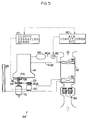
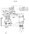
- an air conditioner 64 applied to the second embodiment is provided with the heater core 38 in the air-conditioning duct 32, but is not provided with the radiator 36.
- a pair of hot-water pipes 40A and 40B are connected to the heater core 38 and between the engine 14 and the heater core 38.
- the operation of the electrically operated pump 42 provided in the hot-water pipe 40A allows circulation of a water refrigerant between the engine 14 and the heater core 38.
- a heat storage tank 66 is provided in the hot-water pipe 40A between the electrically operated pump 42 and the engine 14. When the engine 14 is driven, heat for heating is stored in the heat storage tank 66.
- a V belt 26 is entrained between a pulley 22 mounted to the driving shaft 20A of the compressor 20 and a pulley 24 mounted to the output shaft 18.
- a clutch 68 serving as driving force switching means is provided in the output shaft 18 between the pulley 24 and the engine 14.
- the clutch 68 is operated by a clutch operating means 70 so that the driving shaft 14A of the engine 14 and the output shaft 18 are separated from each other in a relatively rotatable manner.
- the clutch operating means 70 is connected to the air-conditioner ECU 60.
- the air-conditioner ECU 60 When the air conditioner 64 is operated while the electric motor 16 is being driven, the air-conditioner ECU 60 outputs an operation signal of the clutch 68 to the clutch operating means 70.
- the clutch operating means 70 operates the clutch 68 so as to separate the output shaft 18 and the driving shaft 14A of the engine from each other.
- the heating operation when the heating operation is indicated (the heating mode is set by an unillustrated operation panel) with the engine 14 being driven, a water refrigerant is circulated between the engine 14 and the heater core 38.
- the water refrigerant which has been heated to a high temperature by cooling the engine 14 passes through the heater core 38 and heats air to be blown out into the vehicle interior, thereby allowing heating for the vehicle interior.
- the compressor 20 when air-cooling or dehumidification of the vehicle interior is carried out, the compressor 20 is actuated.
- the driving force of the engine 14 is transmitted from the driving shaft 14A to the output shaft 18 via the clutch 68.
- the rotation of the output shaft 18 is transmitted from the pulley 24 to the pulley 22 mounted to the driving shaft 20A of the compressor 20 by the V belt 26 and the compressor 20 is thereby driven.
- the operation signal of the clutch 68 is outputted to the clutch operating means 70.
- the clutch operating means 70 operates the clutch 68 so as to separate the output shaft 18 and the driving shaft 14A of the engine 14 from each other.
- the compressor 20 is driven to rotate by the electric motor 16 by separating the output shaft 18 to which the driving force of the electric motor 16 is outputted and the driving shaft 14A of the engine 14 from each other, there is no possibility of application of a large load which impedes driving of the electric motor 16, and the air conditioner 64 can be operated by the driving force of the electric motor 16.
- FIG. 6 shows a schematic structure of an air conditioner 200 applied to the third embodiment.
- a hybrid car equipped with the air conditioner 200 includes an engine 202 and an electric motor 204. Only the layout of the engine 202 and the electric motor 204 is different from the layout shown in the first and second embodiments, but each basic operation of the engine 202 and the electric motor 204 is the same as that of the engine 14 and the electric motor 16, which are applied to each of the first and second embodiments.
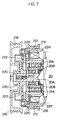
- a double pulley clutch 206 serving as driving force switching means is mounted to the driving shaft 20A of the compressor 20 in the air conditioner 200.
- the driving shaft 20A of the compressor 20 is disposed rotatably so as to project from a cylindrical housing 208, which projects from a compressor main body, with a bearing 210 interposed between the driving shaft 20A and the housing 208.
- a driving wheel 212 is disposed on an outer peripheral surface of the housing 208.
- the driving wheel 212 is rotatably supported by the housing 208 via a bearing 214 mounted on the outer peripheral surface of the housing 208.
- a pulley 216 is formed on an outer peripheral surface of the driving wheel 212 and the driving wheel 212 is rotated by driving force transmitted thereto via the pulley 216.
- a pulley 218 is mounted at an end portion of the driving shaft 20A of the compressor 20 projecting from the housing 208 and the driving shaft 20A thereby rotates integrally with the pulley 218.
- a passive wheel 220 is disposed in the driving shaft 20A of the compressor 20 between the pulley 218 and the driving wheel 212.
- the passive wheel 220 rotates integrally with the driving shaft 20A.
- a passive plate 222 is mounted on the driving wheel 212 side of the surface of the driving wheel 220.
- the passive plate 222 rotates integrally with the passive wheel 220 and is also mounted in such a manner as to be movable along an axial direction of the driving shaft 20A by a small amount.
- a space is formed within the driving wheel 212 and an electromagnetic coil 224 is disposed in the space. Further, the surface of the driving wheel 212 facing the passive plate 222 is formed as a driving plate 226. Namely, the electromagnetic coil 224 and the passive plate 222 are disposed with the driving plate 226 interposed therebetween.
- the electromagnetic coil 224 is mounted to the compressor 20 and is allowed to rotate relatively with the driving wheel 212.
- the passive plate 222 provided in the passive wheel 220 is slightly separated from the driving plate 226 of the driving wheel 212. As a result, the driving wheel 212 and the passive wheel 220 are allowed to rotate relatively. Further, the passive plate 222 adheres closely to the driving plate 226 due to being attracted by magnetic force caused by magnetization of the electromagnetic coil 224. As a result, the passive plate 222 and the driving plate 226 rotate integrally and rotating force transmitted to the pulley 216 is transmitted to the driving shaft 20A of the compressor 20 so as to drive and rotate the driving shaft 20A.
- a V belt 232 serving as first driving force transmitting means is entrained between the pulley 216 mounted to the double pulley clutch 206 and a pulley 230 mounted to a crank shaft 228 of the engine 202. Accordingly, the driving force of the engine 202 is transmitted from the crank shaft 228, which is driven to rotate by driving of the engine 202, to the pulley 218.
- a V belt 236 serving as second driving force transmitting means is entrained between the pulley 218 mounted to the double pulley clutch 206 and the pulley 234 mounted to the driving shaft 204A of the electric motor 204.
- the driving force of the electric motor 204 is transmitted to the driving shaft 20A of the compressor 20 via the V belt 236 and the pulley 218.
- the air conditioner 200 includes an air-conditioner ECU 238 for controlling the operation of the air conditioner 200.
- the air-conditioner ECU 238 is connected to an engine ECU 240 for controlling each operation of the engine 202 and the electric motor 204. Further, the double pulley clutch 206 is controlled by the air-conditioner ECU 238.
- the electromagnetic coil 224 of the double pulley clutch 206 is magnetized by the air-conditioner ECU 238, the driving force of the engine 202 to be transmitted to the pulley 216 is transmitted to the driving shaft 20A of the compressor 20 via the driving plate 226 and the passive plate 222. As a result, the compressor 20 is driven by the driving force of the engine 202. Further, with the electromagnetic coil 224 being brought into a non-magnetized (off) state, the passive plate 224 and the driving plate 226 is allowed to rotate relatively. At this time, even when the electric motor 204 is driven, no driving force of the electric motor 204 is transmitted to the crank shaft 228 of the engine 202 so as to prevent application of a load from the engine 202 to the electric motor 204.
- step 140 it is ascertained whether the air conditioner 200 has been operated (switched on).
- the decision of step 140 is negative and the process proceeds to step 142, in which the electromagnetic coil 224 is switched off.
- the driving plate 226 and the passive plate 222 are allowed to rotate relatively and no driving force of the engine 202 is transmitted to the compressor 20. Further, when the electric motor 204 is driven, no driving force of the electric motor 204 is transmitted to the engine 202.
- step 140 it is ascertained whether the engine 202 is driven.
- step 146 the electromagnetic coil 24 of the double pulley clutch 206 is switched on (magnetized).
- the driving force of the engine 202 is transmitted via the double pulley clutch 206 to the compressor 20, and with the compressor 20 being driven by the driving force of the engine 202, the air conditioner 200 is operated. At this time, it is not necessary that the electric motor 204 be driven, and therefore, the electric motor 204 is set in a stopped state.
- step 148 in which the double pulley clutch 206 is switched off (is not magnetized) and the electric motor 204 is switched on so as to drive the compressor 20.
- the driving force of the electric motor 204 is transmitted to the compressor 20 to drive the compressor 20.
- the electromagnetic coil 224 of the double pulley clutch 206 is set in a non-magnetized state. For this reason, no driving force of the electric motor 204 is transmitted to the engine 202 in a stopped state and no large load is thereby applied to the electric motor 204.
- the clutch 68 is provided, as the driving force switching means, in the output shaft 18 (see Fig. 5). Accordingly, the clutch 68 needs to have a capacity which allows transmission of the maximum driving force generated by the engine 14 and the electric motor 16, which results in a large size and a high cost.
- the maximum load is applied when the compressor 20 is operated at the maximum capacity, and the driving force required at this time can be set at an extremely small value as compared with the maximum driving force of the engine 14 (for example, about one tenth of the maximum driving force). Accordingly, a small capacity of the double pulley clutch 206 for transmission of driving force suffices (for example, about one tenth of the maximum driving force), and therefore, the driving force transmitting means can be formed to be of a small size and also at a low cost.
- an air conditioner 72 applied to the fourth embodiment allows heating by using heat of the engine 14 when the engine 14 is driven. Further, when the engine 14 is stopped, heating can be effected by using heat of the engine 14 stored in the heat storage tank 66 when the electrically operated pump 42 is actuated to drive the engine 14.
- the compressor 20 of the air conditioner 72 is rotated due to the driving force from the output shaft 18 to which the engine 14 and the electric motor 16 are each connected.
- An engine ECU 74 which controls the operation of the engine 14 is connected to the air-conditioner ECU 60.
- the engine ECU 74 is generally structured to operate based on a conventional publicly-known engine control method to control the engine 14. In the present embodiment, only the structure relating to the present invention will be described herein.
- a throttle valve 76 and a fuel injector 78 are each connected to the engine ECU 74.
- the throttle valve 76 is operated in accordance with an operation of an accelerator pedal (not shown) and the fuel injector 78 is actuated in accordance with the opening of the throttle valve 76 and the operating state of the engine 14. As a result, the proper amounts of both air and fuel are supplied to each cylinder of the engine 14.
- the engine 14 is provided with valve opening means 84 which opens an intake valve 80 and an exhaust valve 82.
- the valve opening means 84 is connected to the engine ECU 74, and based on an operation signal from the engine ECU 74, the valve opening means 84 opens the intake valve 80 and the exhaust valve 82.
- a valve opening signal is outputted to the engine ECU 74.
- the throttle valve 76 is brought into a full-open state and the intake valve 80 and the exhaust valve 82 are opened.
- the injection of fuel from the fuel injector 78 is, of course, prohibited.
- the opening of the throttle valve 76, the intake valve 80, and the exhaust valve 82 may be carried out not only at the time of the operation of the air conditioner 72, but also when the engine 14 is stopped or the electric motor 16 is being driven.
- the air conditioner 72 is operated in such a manner that the compressor 20 is rotated by the driving force of the electric motor 16. At this time, no large friction for rotating the driving shaft 14A of the engine 14 is applied to the electric motor 16, and therefore, the compressor 20 can be driven.
- the engine 14 be actuated when the air conditioner 72 is operated, thereby preventing deterioration of fuel consumption caused by starting the engine 14. Further, it is also not necessary to provide driving means used only for driving the compressor 20 in a state in which the engine 14 is stopped, and therefore, there is no need of an increase in parts for operating the air conditioner 72.
- the method for driving the compressor 20 without starting the engine 14 while the engine 14 is stopped is not limited to the above-described first, second, third, and fourth embodiments.
- a fifth embodiment will be hereinafter described with reference to Fig. 10.
- auxiliary machines such as a power steering pump
- the compressor 20 of the air conditioner 86 is, together with an alternator 88 and a power steering pump 90, driven by the driving force of an auxiliary machine motor 92.
- a V belt 94 is entrained between a pulley 92A mounted to a driving shaft of the auxiliary machine motor 92, a pulley 88A mounted to a driving shaft of the alternator 88, a pulley 90A mounted to a driving shaft of the power steering pump, and a pulley 22 of the compressor 20, and the compressor 20 is rotated by the driving force of the auxiliary machine motor 92.
- the compressor 20 can be driven without starting the engine 14. Further, a plurality of auxiliary machines are driven concurrently without providing driving means used only for driving the compressor 20, and therefore, it is not necessary to provide separate driving means for driving not only the compressor 20 but also the auxiliary machines.
- the alternator 88 is driven by the auxiliary machine motor 92 so as to allow the generation of a voltage different from that of the electric power for driving the electric motor 16.
- the working voltage of the electric motor 16 is set at a high value (for example, about 288V) because the electric motor 16 requires a large driving force.
- a suitable voltage for example, 12V
- electric power of this voltage (12V) can be directly generated by providing the alternator 88, and therefore, an effect that an expensive DC/DC converter becomes unnecessary is obtained, and further, reduction in cost of the parts used for a hybrid car can be achieved.
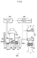
- the pulley 22 is mounted to the driving shaft 20A of the compressor 20 in an air conditioner 250.
- the auxiliary machine motor 92 is provided in the vicinity of an engine 202.
- a V belt 252 serving as third driving force transmitting means is entrained between the pulley 92A of the auxiliary machine motor 92, the pulley 22 of the compressor 20, and a pulley 230 mounted to a crank shaft 228 of the engine 202.
- the air conditioner 250 includes a water pump 254 mounted to the engine 202 in place of the electrically operated pump 42.
- the water pump 254 When the water pump 254 is driven, cooling water for the engine 202 is supplied to the heater core 38 so as to allow the vehicle interior to be heated.
- the V belt 252 is also entrained onto a pulley 256 mounted to a driving shaft 254A of the water pump 254, and the water pump 254 can be driven by the driving force of the engine 202 or the driving force of the auxiliary machine motor 92.
- other auxiliary machines such as the power steering pump 90 and the like (not shown in Fig. 11A) are also connected to the auxiliary machine motor 92, and when the pulley 92A is rotated by the driving force of the engine 202, the rotating force is also transmitted to these other auxiliary machines.
- a crank clutch 258 serving as driving force interruption means is provided in the crank shaft 228 and a compressor clutch 260 is provided in the driving shaft 20A of the compressor 20.
- the crank clutch 258 separates the crank shaft 228 of the engine 202 and the pulley 230 from each other enabling the crank shaft 228 and the pulley 230 to be relatively rotatable.
- the compressor clutch 260 separates the driving shaft 20A of the compressor 20 and the pulley 22 from each other enabling the driving shaft 20A and the pulley 22 to be relatively rotatable.
- crank clutch 258 and the compressor clutch 260 are each connected to an air-conditioner ECU 238, and the auxiliary machine motor 92 can also be driven by being controlled by the air-conditioner ECU 238.
- the air-conditioner ECU 238 is provided to control the auxiliary machine motor 92, the crank clutch 258, and the compressor clutch 260 in accordance with the operating state of the air conditioner 250 and the operating state of the engine 202.
- step 150 it is ascertained whether the engine 202 is started (switched on).
- the process proceeds to step 152, in which the crank clutch 258 is switched on (is connected) and the auxiliary machine motor 92 is stopped (is switched off).
- the V belt 252 is driven to rotate by the driving force of the engine 202 and other auxiliary machines connected to the water pump 254 or the auxiliary machine motor 92 are driven by the driving force of the engine 202.
- step 154 it is ascertained whether the air conditioner 250 has been switched on, namely, whether the compressor 20 need to be driven.
- the process proceeds to step 156, in which the compressor clutch 260 is switched on.
- the driving force of the engine 202 is transmitted to the compressor 20 and the compressor 20 is thereby driven by the driving force of the engine 202.
- step 158 in which the compressor clutch 260 is switched off.
- the compressor 20 is not driven and the water pump 254 is driven, and therefore, heating is made possible.
- other auxiliary machines connected to the auxiliary machine motor 92 are also driven by the driving force of the engine 202.
- step 160 in which the crank clutch 258 is switched off and the crank shaft 228 and the pulley 230 are separated from each other.
- step 162 it is ascertained whether the air conditioner 250 has been switched on.
- the process proceeds to step 164, in which the compressor clutch 260 is switched on and the auxiliary machine motor 92 is driven (switched on).
- the driving force of the auxiliary machine motor 92 is transmitted to the compressor 20 and also to the water pump 254 and the air conditioner 250 is operated by the driving force of the auxiliary machine motor 92.
- step 162 when the air conditioner 250 has not been switched on (when the decision of step 162 is negative), the process proceeds to step 166, in which the compressor clutch 260 is switched off.
- step 168 it is ascertained whether the heating operation is being effected, i.e., whether the heating operation is to be effected.
- step 170 the auxiliary machine motor 92 is driven.
- the driving force of the auxiliary machine motor 92 is transmitted via the V belt 252 to the water pump 254 and cooling water of the engine 202 is supplied to the heater core 38.
- the crank clutch 258 and the compressor clutch 260 are each switched off, and therefore, there is no possibility of an unnecessary load being applied to the auxiliary machine motor 92.
- step 172 in which the auxiliary machine motor 92 is left stopped. At this time, if it is necessary to operate other auxiliary machines connected to the auxiliary machine motor 92, the auxiliary machine motor 92 may be operated.
- the air conditioner 250 applied to the fifth embodiment as well, it is not necessary to use a motor used only for driving the compressor 20 and also not necessary to start the engine 202, thereby preventing deterioration of fuel consumption which is caused due to the engine 202 driving the compressor 20. Further, it is not necessary to provide the electrically operated pump 42 which is used to supply cooling water to the heater core 38 for the heating operation, and therefore, reduction in the number of parts and reduction in costs can be achieved.
- the transmission of driving force to the compressor 20 and the switching of a driving source are not limited to the aforementioned.
- a V belt 262 may be entrained between the pulley 216 and the pulley 92A of the auxiliary machine motor 92 and a V belt 264 may be entrained between the other pulley 218, a pulley 230, and a pulley 256.
- the double pulley clutch 206 be switched on at the time of operation (including a heating operation) of the air conditioner 250 using the auxiliary machine motor 92. Further, when the air conditioner 250 is not operated, so long as the double pulley clutch 206 is switched off, only the other auxiliary machines can be driven by the auxiliary machine motor 92 as occasion demands.
- the air-conditioner ECU 238 is used as the control means.
- the crank clutch 258, the compressor clutch 260, and the auxiliary machine motor may be each controlled by the engine ECU.
- a controller used only for these devices may be provided.
- the description given was that for a hybrid car, but the present invention can also be applied to vehicles of various structures, each traveling by the driving force of an engine without using an electric motor.
- a so-called economy running system has been proposed in which the engine is stopped when the vehicle stops so as to improve fuel consumption and also inhibit emission of exhaust gas.
- the economy running system when the engine is stopped, driving of the compressor is also stopped.
- the present invention when the present invention is applied, the vehicle interior can be maintained in a comfortable air-conditioned state without stopping air conditioning in the vehicle interior.
- an alternator/starter motor can be used in place of the electric motor.
- the alternator/starter motor operates as a starter motor at the time of starting the engine, and during the operation of the engine, it operates as an alternator which generates power by the driving force of the engine.
- air conditioning for the vehicle interior can be carried out by driving the compressor while effecting power generation/charging by the alternator/starter motor.
- the above-described present invention allows air-cooling and heating in which the power of an engine is efficiently utilized. Further, the present invention also allows the driving of a compressor by an electric motor without starting an engine and is useful as an air conditioner not only for a vehicle which travels by the driving force of the engine, but also for a hybrid car which travels by the driving force of the electric motor in addition to that of the engine.
Landscapes
- Engineering & Computer Science (AREA)
- Mechanical Engineering (AREA)
- Physics & Mathematics (AREA)
- Thermal Sciences (AREA)
- Chemical & Material Sciences (AREA)
- Combustion & Propulsion (AREA)
- General Engineering & Computer Science (AREA)
- Air-Conditioning For Vehicles (AREA)
- Hybrid Electric Vehicles (AREA)
Abstract
Description
Claims (8)
- An air conditioner for a vehicle, which air conditions a vehicle interior by a refrigerating cycle formed to include a compressor and an evaporator, said air conditioner for a vehicle comprising a water cooling cycle which is formed by water refrigerant heat exchange means provided in the refrigerating cycle and cooling water which is supplied as a refrigerant, heat storage means for cooling in which one of water cooled by said water-refrigerant heat exchange means and cooling heat obtained from water is stored, and heat dissipation means for cooling which cools air to be blown out into the vehicle interior by water supplied as a refrigerant from said heat storage means for cooling.
- An air conditioner for a vehicle according to claim 1, comprising a water heating cycle which is formed by heat storage means for heating in which one of water heated by an engine and heating heat obtained from water is stored, and heat dissipation means for heating, which heats air to be blown out into the vehicle interior by supplying, as a refrigerant, one of cooling water for the engine and water heated by heat stored in said heat storage means for heating so as to allow heating of the vehicle interior.
- An air conditioner for a vehicle according to claim 2, comprising: heat storage means which can be used as both the heat storage means for cooling and also as the heat storage means for heating; first circulating means which can circulate water which becomes a refrigerant between the engine and said heat dissipation means for heating; second circulating means which can circulate water which becomes a refrigerant between said water-refrigerant heat exchange means and said heat dissipation means for cooling; and circulating passage switching means which changes said heat storage means to said first circulating means and said second circulating means to allow circulation of the water by any one of said first circulating means and said second circulating means.
- An air conditioner for a vehicle, which is provided in a vehicle equipped with an engine and an electric motor and which air conditions a vehicle interior by a refrigerating cycle formed to include a compressor and an evaporator, said air conditioner for a vehicle comprising: driving shafts provided respectively in the engine and in the electric motor; an output shaft connected to said driving shafts of the engine and the electric motor and rotated synchronously with a driving source which is one of the engine and the electric motor; driving force transmitting means which connects a driving shaft of one of the engine and the electric motor and a driving shaft of the compressor so as to transmit a driving force of said output shaft to the compressor; and driving force switching means which switches a driving source of the driving force to be transmitted to the driving shaft of the compressor by said driving force transmitting means.
- An air conditioner for a vehicle according to claim 4, wherein said driving force switching means is clutch means provided between the driving shafts of the engine and the electric motor and said output shaft.
- An air conditioner for a vehicle according to claim 4, comprising: first driving force transmitting means, which is provided as said driving force transmitting means, for transmitting driving force from the driving shaft of the engine to the driving shaft of the compressor; second driving force transmitting means which transmits driving force from the driving shaft of the electric motor to the driving shaft of the compressor; and clutch means which is provided as said driving force switching means and separates one of said first driving force transmitting means and said second driving force transmitting means from the driving shaft of the compressor.
- An air conditioner for a vehicle, which is provided in a vehicle equipped with an engine and an electric motor and which air conditions a vehicle interior by a refrigerating cycle formed to include a compressor and an evaporator, said air conditioner for a vehicle comprising: driving shafts provided respectively in the engine and in the electric motor; an output shaft connected to said driving shafts of the engine and the electric motor and rotated synchronously with a driving source which is one of the engine and the electric motor; load reduction means for reducing the driving load of said output shaft which rotates integrally with the driving shaft of the engine when the electric motor is driven; and driving force transmitting means which connects said output shaft and the driving shaft of the compressor to transmit the driving force of said output shaft to the compressor.
- An air conditioner for a vehicle, which is provided in a vehicle equipped with an engine and an electric motor and which air conditions a vehicle interior by a refrigerating cycle formed to include a compressor and an evaporator, said air conditioner for a vehicle comprising: an auxiliary-machine motor which drives a plurality of auxiliary machines provided in the vehicle; third driving force transmitting means which can transmit the driving force of the engine and the driving force of said auxiliary-machine motor to the plurality of auxiliary machines and also to the driving shaft of the compressor; driving force interrupting means which interrupts the driving shaft of the engine and said third driving force transmitting means; and control means which controls said driving force interrupting means and said auxiliary-machine motor in accordance with a state in which the engine is driven.
Priority Applications (1)
| Application Number | Priority Date | Filing Date | Title |
|---|---|---|---|
| EP07011205A EP1829720A3 (en) | 1996-10-01 | 1997-10-01 | Air conditioning apparatus for vehicle |
Applications Claiming Priority (5)
| Application Number | Priority Date | Filing Date | Title |
|---|---|---|---|
| JP26101696 | 1996-10-01 | ||
| JP26101696 | 1996-10-01 | ||
| JP570997 | 1997-01-16 | ||
| JP570997 | 1997-01-16 | ||
| PCT/JP1997/003505 WO1998015420A1 (en) | 1996-10-01 | 1997-10-01 | Air conditioning apparatus for vehicle |
Related Child Applications (1)
| Application Number | Title | Priority Date | Filing Date |
|---|---|---|---|
| EP07011205A Division EP1829720A3 (en) | 1996-10-01 | 1997-10-01 | Air conditioning apparatus for vehicle |
Publications (3)
| Publication Number | Publication Date |
|---|---|
| EP0930185A1 true EP0930185A1 (en) | 1999-07-21 |
| EP0930185A4 EP0930185A4 (en) | 2001-08-22 |
| EP0930185B1 EP0930185B1 (en) | 2007-08-15 |
Family
ID=26339699
Family Applications (2)
| Application Number | Title | Priority Date | Filing Date |
|---|---|---|---|
| EP07011205A Ceased EP1829720A3 (en) | 1996-10-01 | 1997-10-01 | Air conditioning apparatus for vehicle |
| EP97942219A Expired - Lifetime EP0930185B1 (en) | 1996-10-01 | 1997-10-01 | Air conditioning apparatus for vehicle |
Family Applications Before (1)
| Application Number | Title | Priority Date | Filing Date |
|---|---|---|---|
| EP07011205A Ceased EP1829720A3 (en) | 1996-10-01 | 1997-10-01 | Air conditioning apparatus for vehicle |
Country Status (5)
| Country | Link |
|---|---|
| US (1) | US6427472B1 (en) |
| EP (2) | EP1829720A3 (en) |
| JP (1) | JP3432232B2 (en) |
| DE (1) | DE69738026T2 (en) |
| WO (1) | WO1998015420A1 (en) |
Cited By (5)
| Publication number | Priority date | Publication date | Assignee | Title |
|---|---|---|---|---|
| EP1249360A1 (en) * | 2001-04-10 | 2002-10-16 | Denso Corporation | Accessory equipment driving device for vehicle |
| EP1316453A1 (en) * | 2001-11-28 | 2003-06-04 | Denso Corporation | Functional combined equipment for motor vehicle |
| WO2004022366A1 (en) * | 2002-09-03 | 2004-03-18 | Robert Bosch Gmbh | Method and system for operating an air conditioner in a motor vehicle |
| WO2008037980A3 (en) * | 2006-09-25 | 2008-05-22 | Univ Sussex | Vehicle power supply system |
| WO2008112046A2 (en) | 2007-03-07 | 2008-09-18 | The Gates Corporation | Vehicle stop/start system with regenerative braking |
Families Citing this family (16)
| Publication number | Priority date | Publication date | Assignee | Title |
|---|---|---|---|---|
| DE10065002A1 (en) * | 2000-12-23 | 2002-07-11 | Bosch Gmbh Robert | Cooling arrangement and method |
| JP3801027B2 (en) * | 2001-11-26 | 2006-07-26 | 株式会社デンソー | Air conditioner for vehicles |
| JP3775351B2 (en) * | 2002-06-12 | 2006-05-17 | 株式会社デンソー | HYBRID COMPRESSOR DEVICE AND HYBRID COMPRESSOR CONTROL METHOD |
| US20040144107A1 (en) * | 2003-01-27 | 2004-07-29 | Matthew Breton | HVAC controls for a vehicle with start-stop engine operation |
| DE102004019607A1 (en) | 2004-04-22 | 2006-01-12 | Webasto Ag | Heating and air conditioning system for a motor vehicle |
| CA2578992A1 (en) * | 2004-08-31 | 2006-03-09 | Groupe Enerstat Inc. | Climate control system for vehicle berths and cabs |
| US7412843B2 (en) | 2005-05-20 | 2008-08-19 | Martin Perry Heard | Manifold-superheated air conditioning system |
| US20090191804A1 (en) * | 2008-01-29 | 2009-07-30 | Lakhi Nandlal Goenka | Heating, ventilating, and air conditioning system having a thermal energy exchanger |
| US9038400B2 (en) | 2009-05-18 | 2015-05-26 | Gentherm Incorporated | Temperature control system with thermoelectric device |
| DE102010037446A1 (en) * | 2010-09-10 | 2012-03-15 | Ford Global Technologies, Llc. | Method for controlling an air conditioning system |
| JP5920178B2 (en) * | 2011-12-05 | 2016-05-18 | 株式会社デンソー | Heat pump cycle |
| US9389007B1 (en) * | 2013-01-09 | 2016-07-12 | New West Technologies, LLC | Transportation refrigeration system with integrated power generation and energy storage |
| US20140208794A1 (en) * | 2013-01-30 | 2014-07-31 | Visteon Global Technologies, Inc. | Thermal energy exchanger with heat pipe |
| JP6751716B2 (en) | 2014-12-19 | 2020-09-09 | ジェンサーム インコーポレイテッドGentherm Incorporated | Vehicle area thermal control systems and methods |
| US10625566B2 (en) | 2015-10-14 | 2020-04-21 | Gentherm Incorporated | Systems and methods for controlling thermal conditioning of vehicle regions |
| DE102019101371A1 (en) * | 2019-01-21 | 2020-07-23 | Volkswagen Aktiengesellschaft | Method for operating a hybrid vehicle |
Family Cites Families (28)
| Publication number | Priority date | Publication date | Assignee | Title |
|---|---|---|---|---|
| US2865558A (en) * | 1954-01-22 | 1958-12-23 | Otto J Schemmel | Hydraulically operated compressors |
| US2962873A (en) * | 1959-03-30 | 1960-12-06 | Polar Bear Inc | Refrigeration system |
| US3941012A (en) * | 1974-02-11 | 1976-03-02 | Westinghouse Electric Corporation | Dual drive mechanism |
| GB1510779A (en) * | 1974-05-24 | 1978-05-17 | Ass Eng Ltd | Air-conditioning systems |
| US4587936A (en) * | 1981-09-10 | 1986-05-13 | Honda Giken Kogyo Kabushiki Kaisha | Control apparatus for intake and exhaust valves of an internal combustion engine |
| JPS58211906A (en) * | 1982-06-03 | 1983-12-09 | Nissan Motor Co Ltd | Vehicle air conditioner |
| JPS59114106A (en) | 1982-12-21 | 1984-07-02 | Nissan Motor Co Ltd | Regenerator of space heating apparatus for vehicle |
| JPS61150818A (en) * | 1984-12-22 | 1986-07-09 | Nippon Denso Co Ltd | Air conditioner for automobile |
| JPS639023A (en) | 1986-06-30 | 1988-01-14 | Matsushita Electric Ind Co Ltd | Production of magnetic recording tape |
| JPH0343045Y2 (en) * | 1986-07-07 | 1991-09-10 | ||
| JPS6335843A (en) | 1986-07-24 | 1988-02-16 | ユニチカ株式会社 | Polyester processed product and its production |
| JPH03266765A (en) * | 1990-03-16 | 1991-11-27 | Hitachi Ltd | Air conditioning system for railway vehicles |
| JPH04126628A (en) * | 1990-09-19 | 1992-04-27 | Hitachi Ltd | Driving method of compressor for vehicle cooling system |
| JP3119281B2 (en) * | 1991-10-14 | 2000-12-18 | 株式会社デンソー | Vehicle air conditioner |
| JPH05328521A (en) | 1992-05-15 | 1993-12-10 | Mitsubishi Motors Corp | How to drive a hybrid vehicle |
| JPH064344A (en) | 1992-06-17 | 1994-01-14 | Hokkaido Nippon Denki Software Kk | Displaying the type of the referenced variable in the program |
| JPH064344U (en) * | 1992-06-26 | 1994-01-21 | 富士重工業株式会社 | Hybrid engine controller |
| US5277038A (en) * | 1992-08-28 | 1994-01-11 | Instatherm Company | Thermal storage system for a vehicle |
| JPH06156062A (en) | 1992-11-17 | 1994-06-03 | Toyota Motor Corp | Cold/heat-storing type air conditioner |
| JP3180506B2 (en) | 1993-03-31 | 2001-06-25 | 株式会社エクォス・リサーチ | Air conditioning control device for hybrid vehicle |
| US5558173A (en) * | 1993-09-23 | 1996-09-24 | General Motors Corporation | Integrated hybrid transmission with mechanical accessory drive |
| US5553662A (en) * | 1993-12-10 | 1996-09-10 | Store Heat & Producte Energy, Inc. | Plumbed thermal energy storage system |
| DE19513710B4 (en) * | 1994-04-20 | 2006-05-04 | Volkswagen Ag | Method for operating an air conditioning system and arrangement thereof in a motor vehicle |
| JP3045015B2 (en) * | 1994-09-28 | 2000-05-22 | トヨタ自動車株式会社 | Control method of hybrid electric vehicle |
| JPH08142642A (en) * | 1994-11-17 | 1996-06-04 | Mitsubishi Heavy Ind Ltd | Air conditioner for vehicle |
| FR2727902A1 (en) * | 1994-12-09 | 1996-06-14 | Valeo Thermique Habitacle | DEVICE FOR AIR CONDITIONING A VEHICLE IN TRAFFIC AND PARKING |
| JP3266765B2 (en) | 1995-07-19 | 2002-03-18 | キヤノン株式会社 | Facsimile machine |
| JPH09267647A (en) * | 1996-04-02 | 1997-10-14 | Honda Motor Co Ltd | Power transmission mechanism of hybrid vehicle |
-
1997
- 1997-10-01 JP JP51737398A patent/JP3432232B2/en not_active Expired - Fee Related
- 1997-10-01 WO PCT/JP1997/003505 patent/WO1998015420A1/en not_active Ceased
- 1997-10-01 EP EP07011205A patent/EP1829720A3/en not_active Ceased
- 1997-10-01 DE DE69738026T patent/DE69738026T2/en not_active Expired - Lifetime
- 1997-10-01 EP EP97942219A patent/EP0930185B1/en not_active Expired - Lifetime
-
1999
- 1999-03-31 US US09/282,422 patent/US6427472B1/en not_active Expired - Fee Related
Cited By (9)
| Publication number | Priority date | Publication date | Assignee | Title |
|---|---|---|---|---|
| EP1249360A1 (en) * | 2001-04-10 | 2002-10-16 | Denso Corporation | Accessory equipment driving device for vehicle |
| US6801842B2 (en) | 2001-04-10 | 2004-10-05 | Denso Corporation | Accessory equipment driving device for vehicle |
| EP1316453A1 (en) * | 2001-11-28 | 2003-06-04 | Denso Corporation | Functional combined equipment for motor vehicle |
| US6729998B2 (en) | 2001-11-28 | 2004-05-04 | Denso Corporation | Functional combined equipment for motor vehicle |
| WO2004022366A1 (en) * | 2002-09-03 | 2004-03-18 | Robert Bosch Gmbh | Method and system for operating an air conditioner in a motor vehicle |
| WO2008037980A3 (en) * | 2006-09-25 | 2008-05-22 | Univ Sussex | Vehicle power supply system |
| WO2008112046A2 (en) | 2007-03-07 | 2008-09-18 | The Gates Corporation | Vehicle stop/start system with regenerative braking |
| WO2008112046A3 (en) * | 2007-03-07 | 2009-08-06 | Gates Corp | Vehicle stop/start system with regenerative braking |
| CN101626931B (en) * | 2007-03-07 | 2013-03-27 | 盖茨公司 | Vehicle stop/start system with regenerative braking |
Also Published As
| Publication number | Publication date |
|---|---|
| EP0930185A4 (en) | 2001-08-22 |
| DE69738026D1 (en) | 2007-09-27 |
| WO1998015420A1 (en) | 1998-04-16 |
| EP1829720A3 (en) | 2007-09-26 |
| DE69738026T2 (en) | 2008-05-15 |
| JP3432232B2 (en) | 2003-08-04 |
| EP0930185B1 (en) | 2007-08-15 |
| EP1829720A2 (en) | 2007-09-05 |
| US6427472B1 (en) | 2002-08-06 |
Similar Documents
| Publication | Publication Date | Title |
|---|---|---|
| EP0930185A1 (en) | Air conditioning apparatus for vehicle | |
| JP4526755B2 (en) | Air conditioner for vehicles | |
| JPWO1998015420A1 (en) | Vehicle air conditioning system | |
| US6823690B2 (en) | Integrated electrical generator/starter and air conditioning compressor device and system and method for controlling same | |
| US7007856B2 (en) | Extended engine off passenger climate control system and method | |
| US6755033B2 (en) | Hybrid compressor apparatus and method of controlling the same | |
| JPH07304338A (en) | Battery cooling device for electric vehicles | |
| JP2003326962A (en) | Vehicle air conditioner | |
| US6367272B1 (en) | Compressor capacity control system and method | |
| US20080264088A1 (en) | Reversible mode vehicle heating and cooling system for vehicles and method therefor | |
| JP3918328B2 (en) | Air conditioner for vehicles | |
| US6659727B2 (en) | Control method for a dual mode compressor drive system | |
| JP4669640B2 (en) | Air conditioner for vehicles | |
| JP3381592B2 (en) | Hybrid vehicle air conditioner | |
| JP2002370529A (en) | Air-conditioner for vehicle | |
| KR101154207B1 (en) | Heat system control method for hybrid vehicle | |
| JP4156955B2 (en) | Driving method of hybrid compressor for vehicle air conditioner | |
| JP3928959B2 (en) | Vehicle with air conditioner | |
| KR100642131B1 (en) | Compressor drive device of hybrid vehicle and control method of compressor drive device | |
| JP3656439B2 (en) | Air conditioner for vehicles | |
| JP4447390B2 (en) | Cooling method for heat generating equipment for vehicles | |
| JP2003146061A (en) | Air-conditioning system for automobile | |
| JPH11245657A (en) | Engine control device for hybrid electric vehicle | |
| JPH11190213A (en) | Engine cooling system for hybrid vehicles | |
| JP2005101349A (en) | Inverter cooling structure |
Legal Events
| Date | Code | Title | Description |
|---|---|---|---|
| PUAI | Public reference made under article 153(3) epc to a published international application that has entered the european phase |
Free format text: ORIGINAL CODE: 0009012 |
|
| 17P | Request for examination filed |
Effective date: 19990503 |
|
| AK | Designated contracting states |
Kind code of ref document: A1 Designated state(s): DE FR GB |
|
| RIC1 | Information provided on ipc code assigned before grant |
Free format text: 7B 60H 1/08 A, 7B 60H 1/32 B, 7B 60H 1/00 B |
|
| A4 | Supplementary search report drawn up and despatched |
Effective date: 20010705 |
|
| AK | Designated contracting states |
Kind code of ref document: A4 Designated state(s): DE FR GB |
|
| 17Q | First examination report despatched |
Effective date: 20040827 |
|
| GRAP | Despatch of communication of intention to grant a patent |
Free format text: ORIGINAL CODE: EPIDOSNIGR1 |
|
| GRAS | Grant fee paid |
Free format text: ORIGINAL CODE: EPIDOSNIGR3 |
|
| GRAA | (expected) grant |
Free format text: ORIGINAL CODE: 0009210 |
|
| AK | Designated contracting states |
Kind code of ref document: B1 Designated state(s): DE FR GB |
|
| REG | Reference to a national code |
Ref country code: GB Ref legal event code: FG4D |
|
| REF | Corresponds to: |
Ref document number: 69738026 Country of ref document: DE Date of ref document: 20070927 Kind code of ref document: P |
|
| ET | Fr: translation filed | ||
| PLBE | No opposition filed within time limit |
Free format text: ORIGINAL CODE: 0009261 |
|
| STAA | Information on the status of an ep patent application or granted ep patent |
Free format text: STATUS: NO OPPOSITION FILED WITHIN TIME LIMIT |
|
| 26N | No opposition filed |
Effective date: 20080516 |
|
| PGFP | Annual fee paid to national office [announced via postgrant information from national office to epo] |
Ref country code: DE Payment date: 20100929 Year of fee payment: 14 |
|
| PGFP | Annual fee paid to national office [announced via postgrant information from national office to epo] |
Ref country code: GB Payment date: 20110928 Year of fee payment: 15 |
|
| PGFP | Annual fee paid to national office [announced via postgrant information from national office to epo] |
Ref country code: FR Payment date: 20111103 Year of fee payment: 15 |
|
| GBPC | Gb: european patent ceased through non-payment of renewal fee |
Effective date: 20121001 |
|
| REG | Reference to a national code |
Ref country code: FR Ref legal event code: ST Effective date: 20130628 |
|
| PG25 | Lapsed in a contracting state [announced via postgrant information from national office to epo] |
Ref country code: GB Free format text: LAPSE BECAUSE OF NON-PAYMENT OF DUE FEES Effective date: 20121001 Ref country code: DE Free format text: LAPSE BECAUSE OF NON-PAYMENT OF DUE FEES Effective date: 20130501 |
|
| REG | Reference to a national code |
Ref country code: DE Ref legal event code: R119 Ref document number: 69738026 Country of ref document: DE Effective date: 20130501 |
|
| PG25 | Lapsed in a contracting state [announced via postgrant information from national office to epo] |
Ref country code: FR Free format text: LAPSE BECAUSE OF NON-PAYMENT OF DUE FEES Effective date: 20121031 |