EP0930005A2 - Truck for shredding and mixing products for zootechnical use - Google Patents
Truck for shredding and mixing products for zootechnical use Download PDFInfo
- Publication number
- EP0930005A2 EP0930005A2 EP99100391A EP99100391A EP0930005A2 EP 0930005 A2 EP0930005 A2 EP 0930005A2 EP 99100391 A EP99100391 A EP 99100391A EP 99100391 A EP99100391 A EP 99100391A EP 0930005 A2 EP0930005 A2 EP 0930005A2
- Authority
- EP
- European Patent Office
- Prior art keywords
- container
- truck
- truck according
- opening
- fodder
- Prior art date
- Legal status (The legal status is an assumption and is not a legal conclusion. Google has not performed a legal analysis and makes no representation as to the accuracy of the status listed.)
- Granted
Links
- 230000033001 locomotion Effects 0.000 claims abstract description 11
- 238000007599 discharging Methods 0.000 claims description 4
- 238000009826 distribution Methods 0.000 description 10
- 244000144972 livestock Species 0.000 description 4
- 230000008901 benefit Effects 0.000 description 3
- 230000000295 complement effect Effects 0.000 description 3
- 238000007689 inspection Methods 0.000 description 3
- 239000002184 metal Substances 0.000 description 3
- 230000006872 improvement Effects 0.000 description 2
- 238000000034 method Methods 0.000 description 2
- 238000005457 optimization Methods 0.000 description 2
- 230000008569 process Effects 0.000 description 2
- 238000005303 weighing Methods 0.000 description 2
- 235000006085 Vigna mungo var mungo Nutrition 0.000 description 1
- 240000005616 Vigna mungo var. mungo Species 0.000 description 1
- 230000009471 action Effects 0.000 description 1
- 239000000654 additive Substances 0.000 description 1
- 230000002860 competitive effect Effects 0.000 description 1
- 239000012141 concentrate Substances 0.000 description 1
- 230000003247 decreasing effect Effects 0.000 description 1
- 230000008021 deposition Effects 0.000 description 1
- 230000000694 effects Effects 0.000 description 1
- 238000005516 engineering process Methods 0.000 description 1
- 235000013312 flour Nutrition 0.000 description 1
- 239000004459 forage Substances 0.000 description 1
- 229910052500 inorganic mineral Inorganic materials 0.000 description 1
- 230000000670 limiting effect Effects 0.000 description 1
- 238000004519 manufacturing process Methods 0.000 description 1
- 239000000463 material Substances 0.000 description 1
- 230000009347 mechanical transmission Effects 0.000 description 1
- 239000011707 mineral Substances 0.000 description 1
- 230000004048 modification Effects 0.000 description 1
- 238000012986 modification Methods 0.000 description 1
- 239000004033 plastic Substances 0.000 description 1
- 229920003023 plastic Polymers 0.000 description 1
- 102000004169 proteins and genes Human genes 0.000 description 1
- 108090000623 proteins and genes Proteins 0.000 description 1
- 230000000087 stabilizing effect Effects 0.000 description 1
- 239000010902 straw Substances 0.000 description 1
- 239000000126 substance Substances 0.000 description 1
Images
Classifications
-
- A—HUMAN NECESSITIES
- A01—AGRICULTURE; FORESTRY; ANIMAL HUSBANDRY; HUNTING; TRAPPING; FISHING
- A01K—ANIMAL HUSBANDRY; AVICULTURE; APICULTURE; PISCICULTURE; FISHING; REARING OR BREEDING ANIMALS, NOT OTHERWISE PROVIDED FOR; NEW BREEDS OF ANIMALS
- A01K5/00—Feeding devices for stock or game ; Feeding wagons; Feeding stacks
- A01K5/001—Fodder distributors with mixer or shredder
- A01K5/004—Fodder distributors with mixer or shredder with mixing or shredding element rotating on vertical axis
-
- B—PERFORMING OPERATIONS; TRANSPORTING
- B01—PHYSICAL OR CHEMICAL PROCESSES OR APPARATUS IN GENERAL
- B01F—MIXING, e.g. DISSOLVING, EMULSIFYING OR DISPERSING
- B01F27/00—Mixers with rotary stirring devices in fixed receptacles; Kneaders
- B01F27/80—Mixers with rotary stirring devices in fixed receptacles; Kneaders with stirrers rotating about a substantially vertical axis
- B01F27/92—Mixers with rotary stirring devices in fixed receptacles; Kneaders with stirrers rotating about a substantially vertical axis with helices or screws
-
- B—PERFORMING OPERATIONS; TRANSPORTING
- B01—PHYSICAL OR CHEMICAL PROCESSES OR APPARATUS IN GENERAL
- B01F—MIXING, e.g. DISSOLVING, EMULSIFYING OR DISPERSING
- B01F33/00—Other mixers; Mixing plants; Combinations of mixers
- B01F33/50—Movable or transportable mixing devices or plants
- B01F33/502—Vehicle-mounted mixing devices
- B01F33/5021—Vehicle-mounted mixing devices the vehicle being self-propelled, e.g. truck mounted, provided with a motor, driven by tracks
-
- B—PERFORMING OPERATIONS; TRANSPORTING
- B01—PHYSICAL OR CHEMICAL PROCESSES OR APPARATUS IN GENERAL
- B01F—MIXING, e.g. DISSOLVING, EMULSIFYING OR DISPERSING
- B01F33/00—Other mixers; Mixing plants; Combinations of mixers
- B01F33/50—Movable or transportable mixing devices or plants
- B01F33/502—Vehicle-mounted mixing devices
- B01F33/5023—Vehicle-mounted mixing devices the vehicle being a trailer which is hand moved or coupled to self-propelling vehicles
-
- B—PERFORMING OPERATIONS; TRANSPORTING
- B01—PHYSICAL OR CHEMICAL PROCESSES OR APPARATUS IN GENERAL
- B01F—MIXING, e.g. DISSOLVING, EMULSIFYING OR DISPERSING
- B01F2101/00—Mixing characterised by the nature of the mixed materials or by the application field
- B01F2101/06—Mixing of food ingredients
- B01F2101/18—Mixing animal food ingredients
-
- B—PERFORMING OPERATIONS; TRANSPORTING
- B01—PHYSICAL OR CHEMICAL PROCESSES OR APPARATUS IN GENERAL
- B01F—MIXING, e.g. DISSOLVING, EMULSIFYING OR DISPERSING
- B01F35/00—Accessories for mixers; Auxiliary operations or auxiliary devices; Parts or details of general application
- B01F35/75—Discharge mechanisms
Definitions
- the present invention relates to a truck for shredding and mixing products for zootechnical use.
- Each scroll is welded to a shaft which is rotationally coupled to the bottom of the container and is turned by means of adapted hydraulic and mechanical transmissions which are kinematically connected to actuation elements, such as for example the power take-off of a tractor or directly the engine in the case of a self-propelled truck.
- the products to be mixed are loaded from above, while the product ready for feeding is discharged through an outlet with an opening and closure door which is present on the lateral part of the container, usually in the front region of the truck.
- the aim of the present invention is to provide an improved truck for shredding and mixing products for zootechnical use which solves the above-mentioned drawbacks in known cases and is provided in particular with fodder distribution means whose position and profile do not interfere with the troughs, which are often provided with relatively high walls.
- an important object of the present invention is to provide a truck which allows the operator to adequately view the distribution process.
- a further object of the present invention is to provide a truck in which it is also possible to serve litters at a distance from said truck which exceeds its transverse profile.
- a further object of the present invention is to provide a truck in which the distribution means provide space optimization.
- a further object of the present invention is to provide a truck which can be manufactured with known technologies and at competitive costs with respect to known trucks.
- a truck for shredding and mixing products for zootechnical use which comprises, on a self-propelled or towed wheeled chassis, a mixing container which contains one or more rotating scrolls provided with shredding blades, said container having a front opening for the passage of shredded and mixed fodder, said opening being associated with a closure door which has a vertical shutter-like movement, characterized in that it comprises, at the outlet of said opening, two continuous conveyance elements for conveying and distributing the fodder, a first one of said conveyance elements being arranged longitudinally with respect to the chassis and being arranged adjacent to said opening, a second one of said conveyance elements being arranged transversely with respect to said first one, from which it receives the fodder.
- a truck for shredding and mixing products for zootechnical use is generally designated by the reference numeral 10 in a first embodiment.
- the truck 10 is of the towed type and comprises, on a chassis 11 with wheels 12, a frustum-shaped container 13 which tapers downward and is provided with a scroll 14, shown in dashed lines in the figures, which rotates about a vertical axis and has an external profile which lies on a substantially conical imaginary surface.
- Shredder blades 14a are mounted at said profile and cooperate with complementary blades 14b which can be arranged so as to protrude internally from the container 13.
- the container 13 has an opening 15 for the passage of shredded and mixed fodder which faces the direction of motion of the truck 10, in this case in a front position, and is associated with a closure door 16 which has a vertical shutter-like movement which is produced in this case by an actuator 17 associated with the container 13.
- the truck 10 comprises at the outlet, at the opening 15, two continuous conveyance elements which are constituted in this case by two conveyor belts for conveying and distributing the fodder.
- a first conveyance element 18 is arranged longitudinally with respect to the chassis 11 and is inclined with respect to the ground, with a lower end 19 which is adjacent to the opening 15, and a second conveyance element 20, is arranged transversely to the first one 18 and is adjacent to the upper end thereof, from which it receives the fodder.
- the second conveyor belt 20 has, along the edge that is external with respect to the container 13, a gate 21 (shown in dashed lines in the Figures), which in this case can be turned over outward.
- the second conveyor belt 20 is fixed to a supporting structure, designated by the reference numeral 22, which oscillates and is moved by the corresponding actuation means, not shown (for example a hydraulic cylinder), with a rotation axis which is substantially parallel to the longitudinal axis of the chassis 11.
- actuation means for example a hydraulic cylinder
- the second conveyor belt 20 is also movably supported by the structure 22 so that it can perform a translatory motion, in association with corresponding actuation means, not shown (in this case also, for example, a hydraulic cylinder), in a direction which is parallel to its longitudinal extension so as to protrude from the transverse dimensions of the truck 10.
- actuation means not shown (in this case also, for example, a hydraulic cylinder)
- the first belt can be extendable.
- the truck 10 in this case, is also provided with a finned roller 23 which is arranged above the first conveyor belt 18 and is adapted to improve dosage and prevent the occurrence of reverse flows or stagnations of fodder on the belt.
- the roller 23 can also be supported by a pivoted structure which allows it to perform oscillating motions (for example by means of a hydraulic cylinder) in order to make it at least partially enter the container 13.
- At least one magnet 28 can also cooperate with at least one of the two belts, preferably with the first one.
- the magnet is mounted adjacent to the product passage region and is adapted to retain any potentially damaging metal pieces.
- the truck 10 also has, in this case, a blower 24 for aspirating the shredded product, if only straw is introduced, and for discharging it so as to form litters.
- blower 24 It is possible to provide various positions of the blower 24 depending on the operating requirements, for example above the conveyor belt 18 or on the other side of the truck 10.
- the supporting structure 22 which in this case is at least partially formed by means of tubular elements, supports the second conveyor belt 20, the first conveyor belt 18 and the container 13, so that they are mutually rigidly coupled and rest on common load cells 25, so that it is possible to weigh the fodder without the influence of irrelevant weights.
- the truck 10 is also provided with a ladder 26 with an inspection platform 27 which is supported by the chassis 11 and is entirely independent of the structure 22, with which it does not interfere in any way.
- an improved truck for shredding and mixing products for zootechnical use is generally designated by the reference numeral 100 in a second embodiment.
- the truck 100 is of the self-propelled type and also comprises a driver's cabin 101.
- the truck 100 is also provided with a frustum-shaped container 102 which tapers downward, with a rotating scroll 103 which has a vertical axis and an external profile which lies on a substantially conical imaginary surface whereat shredding blades 104 are fitted.
- Complementary blades 104a protrude from the internal surface of the container 102.
- the container 102 has an opening 105 for the passage of the shredded and mixed fodder which faces the direction of motion of the truck 100 and is associated with a closure door 106 which moves in a vertical shutter-like manner.
- the truck 100 comprises, at the outlet of the opening 105, two conveyor belts for conveying and distributing the fodder: a first conveyor belt 107, which is arranged longitudinally with respect to the chassis of the truck 100 and is inclined with respect to the ground, with a lower end 108 in the vicinity of the opening 105, and a second conveyor belt 109, which lies transversely to the first one 107 and is adjacent to the upper vertex thereof.
- the structure of the distribution means allows both to reach beyond the height of some troughs and to reach them even considerably beyond the transverse dimensions of the truck.
- the arrangement of the conveyor belts as described also allows to provide spaces which can be utilized to accommodate auxiliary equipment or motor drives.
- the particular structure of the distribution means constituted by the combination of the first and second conveyor belts does not affect in any way the weighing of the product that is distributed, since the belts are rigidly coupled to the container so as to constitute a very specific tare which can accordingly be easily eliminated when calculating the net weight of the distributed fodder.
- the inclined longitudinal belt has the advantage of conveying the product in the direction in which it is to fall (not at right angles, as currently occurs), consequently avoiding the creation of friction angles and performing a first dosage, decreasing the stress to which the transverse conveyor belt is subjected.
- a consequent important effect is the possibility to use a belt made of plastics, rather than one having a metal structure, which can have a chosen speed for propelling the product into the trough.
- the livestock is moved further away from the discharge elements, preventing the livestock from moving closer and amputating their tongue as currently occurs.
- the present invention is susceptible of numerous modifications and variations, such as the fact that the container may also be horizontal with horizontal internal scrolls.
- the materials and the dimensions may be any according to requirements.
Landscapes
- Chemical Kinetics & Catalysis (AREA)
- Chemical & Material Sciences (AREA)
- Life Sciences & Earth Sciences (AREA)
- Environmental Sciences (AREA)
- Birds (AREA)
- Biodiversity & Conservation Biology (AREA)
- Animal Husbandry (AREA)
- Apparatuses For Bulk Treatment Of Fruits And Vegetables And Apparatuses For Preparing Feeds (AREA)
- Materials Applied To Surfaces To Minimize Adherence Of Mist Or Water (AREA)
- Compositions Of Macromolecular Compounds (AREA)
- Mirrors, Picture Frames, Photograph Stands, And Related Fastening Devices (AREA)
- Preparation Of Clay, And Manufacture Of Mixtures Containing Clay Or Cement (AREA)
- Crushing And Pulverization Processes (AREA)
Abstract
Description
- The present invention relates to a truck for shredding and mixing products for zootechnical use.
- It is known that combined shredding and mixing trucks are already currently commercially available which substantially comprise a chassis with wheels, suitable to facilitate transport, whereon a substantially frustum-shaped container is fixed. The container is internally provided with one or more vertical mixing scrolls.
- Each scroll is welded to a shaft which is rotationally coupled to the bottom of the container and is turned by means of adapted hydraulic and mechanical transmissions which are kinematically connected to actuation elements, such as for example the power take-off of a tractor or directly the engine in the case of a self-propelled truck.
- The products to be mixed, particularly coarse or fibrous forage with mineral protein additives together with concentrates such as flours, mashes, pulps etcetera, are loaded from above, while the product ready for feeding is discharged through an outlet with an opening and closure door which is present on the lateral part of the container, usually in the front region of the truck.
- In order to facilitate the distribution of the product, under the discharge outlet there is a hydraulically-actuated conveyor belt.
- A drawback that has been noted in these trucks is the fact that the conveyor belt, due to problems related to transport, must not protrude considerably from the overall width profile of the truck and is therefore too short to distribute, at the outlet, the mixed product to the intended regions, which are often located far beyond the space occupied by the truck.
- Improvements to the above-described truck have led to the production of a mixing truck which is fully similar to the one described but has a container whereto the support of a discharging conveyor belt is rigidly coupled, said belt being movably coupled to said support.
- The proposed improvement, however, is not final, since it does not fully solve distribution problems because it does not allow the operator, whether on the towing vehicle or in the cabin of the truck if self-propelled, an adequate view of the distribution process occurring at the outlet of the container.
- Moreover, conventional mixing trucks have an inspection ladder in their front part, in practice above the conveyor belt.
- Although the presence of the conveyor belt and of the ladder with an inspection platform is absolutely necessary from a practical point of view, it induces considerable problems as regards spaces and weighing, which must be performed both to obtain the intended dosages of the various substances with respect to each other and to know the exact amount of fodder distributed to the livestock.
- The aim of the present invention is to provide an improved truck for shredding and mixing products for zootechnical use which solves the above-mentioned drawbacks in known cases and is provided in particular with fodder distribution means whose position and profile do not interfere with the troughs, which are often provided with relatively high walls.
- Within the scope of this aim, an important object of the present invention is to provide a truck which allows the operator to adequately view the distribution process.
- A further object of the present invention is to provide a truck in which it is also possible to serve litters at a distance from said truck which exceeds its transverse profile.
- A further object of the present invention is to provide a truck in which the distribution means provide space optimization.
- A further object of the present invention is to provide a truck which can be manufactured with known technologies and at competitive costs with respect to known trucks.
- This aim, these objects and others which will become apparent hereinafter are achieved by a truck for shredding and mixing products for zootechnical use, which comprises, on a self-propelled or towed wheeled chassis, a mixing container which contains one or more rotating scrolls provided with shredding blades, said container having a front opening for the passage of shredded and mixed fodder, said opening being associated with a closure door which has a vertical shutter-like movement, characterized in that it comprises, at the outlet of said opening, two continuous conveyance elements for conveying and distributing the fodder, a first one of said conveyance elements being arranged longitudinally with respect to the chassis and being arranged adjacent to said opening, a second one of said conveyance elements being arranged transversely with respect to said first one, from which it receives the fodder.
- Further characteristics and advantages of the present invention will become apparent from the following detailed description of two embodiments thereof, illustrated only by way of non-limitative example in the accompanying drawings, wherein:
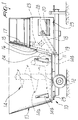
- Figure 1 is a side view of a truck according to the invention in a first embodiment;
- Figure 2 is a rear view of the truck of Figure 1;
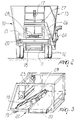
- Figure 3 is a perspective view of a detail of the truck of Figure 1;
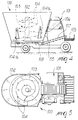
- Figure 4 is a side view of a truck according to the invention in a second embodiment;
- Figure 5 is a plan view of the truck of Figure 4.
-
- With particular reference to Figures 1 to 3, a truck for shredding and mixing products for zootechnical use, according to the invention, is generally designated by the
reference numeral 10 in a first embodiment. - The
truck 10 is of the towed type and comprises, on achassis 11 withwheels 12, a frustum-shapedcontainer 13 which tapers downward and is provided with ascroll 14, shown in dashed lines in the figures, which rotates about a vertical axis and has an external profile which lies on a substantially conical imaginary surface. - Shredder blades 14a are mounted at said profile and cooperate with
complementary blades 14b which can be arranged so as to protrude internally from thecontainer 13. - In particular, the
container 13 has an opening 15 for the passage of shredded and mixed fodder which faces the direction of motion of thetruck 10, in this case in a front position, and is associated with a closure door 16 which has a vertical shutter-like movement which is produced in this case by anactuator 17 associated with thecontainer 13. - The
truck 10 comprises at the outlet, at the opening 15, two continuous conveyance elements which are constituted in this case by two conveyor belts for conveying and distributing the fodder. Afirst conveyance element 18 is arranged longitudinally with respect to thechassis 11 and is inclined with respect to the ground, with alower end 19 which is adjacent to the opening 15, and asecond conveyance element 20, is arranged transversely to thefirst one 18 and is adjacent to the upper end thereof, from which it receives the fodder. - In other cases it is possible to provide other conveyance elements, such as scroll conveyors.
- In particular, the
second conveyor belt 20 has, along the edge that is external with respect to thecontainer 13, a gate 21 (shown in dashed lines in the Figures), which in this case can be turned over outward. - Moreover, the
second conveyor belt 20 is fixed to a supporting structure, designated by the reference numeral 22, which oscillates and is moved by the corresponding actuation means, not shown (for example a hydraulic cylinder), with a rotation axis which is substantially parallel to the longitudinal axis of thechassis 11. - The
second conveyor belt 20 is also movably supported by the structure 22 so that it can perform a translatory motion, in association with corresponding actuation means, not shown (in this case also, for example, a hydraulic cylinder), in a direction which is parallel to its longitudinal extension so as to protrude from the transverse dimensions of thetruck 10. - The latter movement, in particular, allows to combine dimensions of the
truck 10 which are adapted for transporting it even during operation with the need to serve even fodder distribution regions which greatly exceed its transverse dimensions. - As an alternative, the first belt can be extendable.
- The
truck 10, in this case, is also provided with afinned roller 23 which is arranged above thefirst conveyor belt 18 and is adapted to improve dosage and prevent the occurrence of reverse flows or stagnations of fodder on the belt. - The
roller 23 can also be supported by a pivoted structure which allows it to perform oscillating motions (for example by means of a hydraulic cylinder) in order to make it at least partially enter thecontainer 13. - As an alternative it is possible to provide a simple gate located in front of the opening 15.
- At least one
magnet 28 can also cooperate with at least one of the two belts, preferably with the first one. The magnet is mounted adjacent to the product passage region and is adapted to retain any potentially damaging metal pieces. - The
truck 10 also has, in this case, ablower 24 for aspirating the shredded product, if only straw is introduced, and for discharging it so as to form litters. - It is possible to provide various positions of the
blower 24 depending on the operating requirements, for example above theconveyor belt 18 or on the other side of thetruck 10. - As already mentioned, the supporting structure 22, which in this case is at least partially formed by means of tubular elements, supports the
second conveyor belt 20, thefirst conveyor belt 18 and thecontainer 13, so that they are mutually rigidly coupled and rest oncommon load cells 25, so that it is possible to weigh the fodder without the influence of irrelevant weights. - The
truck 10 is also provided with aladder 26 with aninspection platform 27 which is supported by thechassis 11 and is entirely independent of the structure 22, with which it does not interfere in any way. - With particular reference to Figures 4 and 5, an improved truck for shredding and mixing products for zootechnical use, according to the invention, is generally designated by the
reference numeral 100 in a second embodiment. - In particular, the
truck 100 is of the self-propelled type and also comprises a driver'scabin 101. - The
truck 100 is also provided with a frustum-shaped container 102 which tapers downward, with arotating scroll 103 which has a vertical axis and an external profile which lies on a substantially conical imaginary surface whereatshredding blades 104 are fitted. -
Complementary blades 104a protrude from the internal surface of thecontainer 102. - The
container 102 has an opening 105 for the passage of the shredded and mixed fodder which faces the direction of motion of thetruck 100 and is associated with aclosure door 106 which moves in a vertical shutter-like manner. - The
truck 100 comprises, at the outlet of the opening 105, two conveyor belts for conveying and distributing the fodder: afirst conveyor belt 107, which is arranged longitudinally with respect to the chassis of thetruck 100 and is inclined with respect to the ground, with a lower end 108 in the vicinity of the opening 105, and asecond conveyor belt 109, which lies transversely to the first one 107 and is adjacent to the upper vertex thereof. - There is also a gate 109a similar to the preceding one 21.
- Reference is made to the description of the
truck 10 of the first embodiment for further constructive details. - In practice it has been observed that the present invention has achieved the intended aim and objects.
- In particular, it should be observed that the structure of the distribution means allows both to reach beyond the height of some troughs and to reach them even considerably beyond the transverse dimensions of the truck.
- Moreover, in the case of a self-propelled truck, attention is drawn to the excellent view of the state of the distribution of the fodder provided to the operator/driver without having to leave the cabin, furthermore allowing to monitor the product being discharged and the livestock at the same time.
- The arrangement of the conveyor belts as described also allows to provide spaces which can be utilized to accommodate auxiliary equipment or motor drives.
- In particular, it has been possible to move the cabin closer to the container and reduce the distance between the wheels, consequently reducing the overall dimensions of the truck and achieving space optimization.
- It should also be noted that the particular structure of the distribution means constituted by the combination of the first and second conveyor belts does not affect in any way the weighing of the product that is distributed, since the belts are rigidly coupled to the container so as to constitute a very specific tare which can accordingly be easily eliminated when calculating the net weight of the distributed fodder.
- It should also be noted that the inclined longitudinal belt has the advantage of conveying the product in the direction in which it is to fall (not at right angles, as currently occurs), consequently avoiding the creation of friction angles and performing a first dosage, decreasing the stress to which the transverse conveyor belt is subjected.
- A consequent important effect is the possibility to use a belt made of plastics, rather than one having a metal structure, which can have a chosen speed for propelling the product into the trough.
- It should also be noted that the livestock is moved further away from the discharge elements, preventing the livestock from moving closer and amputating their tongue as currently occurs.
- Other advantages observed with respect to conventional trucks are:
- -- the inside of the container cannot be accessed easily, as currently occurs, through the belt and the discharge door;
- -- the discharging action is more uniform, since the longitudinal belt acts as a deposition surface when the initial lower part of the scroll is not adjacent to the opening;
- -- the discharge extensions currently used in many cases because the discharge is currently not adequate to the requirements of stables are eliminated;
- -- there are no more constraints for positioning the complementary blades, as currently entailed by the existing metal plates for protecting the belt;
- -- in towed trucks, the discharge is now closer to the wheels of the tractor and this increases visibility, so as to avoid, during maneuvers, any collision against obstacles with the discharge belt.
-
- The present invention is susceptible of numerous modifications and variations, such as the fact that the container may also be horizontal with horizontal internal scrolls.
- The technical details may be replaced with other technically equivalent elements.
- The materials and the dimensions may be any according to requirements.
- The disclosures in Italian Utility Model Application No. PD98U000008 from which this application claims priority are incorporated herein by reference.
- Where technical features mentioned in any claim are followed by reference signs, those reference signs have been included for the sole purpose of increasing the intelligibility of the claims and accordingly, such reference signs do not have any limiting effect on the interpretation of each element identified by way of example by such reference signs.
Claims (14)
- A truck for shredding and mixing products for zootechnical use, which comprises, on a self-propelled or towed wheeled chassis, a mixing container which contains one or more rotating scrolls provided with shredding blades, said container having a front opening for the passage of shredded and mixed fodder, said opening being associated with a closure door which has a vertical shutter-like movement, characterized in that it comprises, at the outlet of said opening, two continuous conveyance elements for conveying and distributing the fodder, a first one of said conveyance elements being arranged longitudinally with respect to the chassis and being arranged adjacent to said opening, a second one of said conveyance elements being arranged transversely with respect to said first one, from which it receives the fodder.
- The truck according to claim 1, characterized in that said container is frustum-shaped and tapers downward, with a scroll which rotates about a vertical axis and has an external profile which lies on a substantially conical imaginary surface whereat shredder blades are fitted.
- The truck according to claim 1, characterized in that said continuous conveyance elements are conveyor belts.
- The truck according to claim 1, characterized in that said first conveyance element is inclined with respect to the ground, with its lower end adjacent to said opening, and in that said second conveyance element, arranged transversely to the first one, is adjacent to the upper end thereof, from which it receives the fodder.
- The truck according to claim 1, characterized in that said second conveyance element has a gate along the outer edge with respect to said container.
- The truck according to claim 5, characterized in that said gate can be turned over outward with respect to the container.
- The truck according to claim 1, characterized in that said second conveyance element is pivoted to a supporting structure so as to oscillate, being moved by corresponding actuation means, with a rotation axis which is substantially parallel to said first conveyance element.
- The truck according to claim 1, characterized in that said second conveyance element is movably supported by said structure so as to perform a translatory motion, in association with corresponding actuation means, in a direction which is substantially parallel to its longitudinal extension, so as to protrude from the transverse dimensions of said truck.
- The truck according to claim 1, characterized in that it comprises a finned roller which is arranged substantially so as to lie above said first conveyance element adjacent to said opening.
- The truck according to claim 9, characterized in that said finned roller is supported by a pivoted structure which allows, by means of an actuator, oscillating movements thereof in order to make it enter the container at least partially.
- The truck according to claim 1, characterized in that a gate is arranged in front of said opening of said container.
- The truck according to claim 1, characterized in that it comprises a blower for aspirating the fodder from said container and for discharging it so as to produce litters.
- The truck according to claim 1, characterized in that at least one magnet cooperates with at least one of said continuous conveyance elements, said magnet being installed adjacent to a product passage region and being adapted to retain any potentially damaging metallic objects.
- The truck according to claim 1, characterized in that said container and said first and second conveyance elements are mutually rigidly coupled and rest on load cells.
Applications Claiming Priority (2)
| Application Number | Priority Date | Filing Date | Title |
|---|---|---|---|
| IT1998PD000008U IT245022Y1 (en) | 1998-01-20 | 1998-01-20 | PERFECTED WAGON FOR SHREDDING AND MIXING OF ZOOTECHNICAL PRODUCTS |
| ITPD980008U | 1998-01-20 |
Publications (3)
| Publication Number | Publication Date |
|---|---|
| EP0930005A2 true EP0930005A2 (en) | 1999-07-21 |
| EP0930005A3 EP0930005A3 (en) | 2000-01-05 |
| EP0930005B1 EP0930005B1 (en) | 2002-10-16 |
Family
ID=11392015
Family Applications (1)
| Application Number | Title | Priority Date | Filing Date |
|---|---|---|---|
| EP99100391A Expired - Lifetime EP0930005B1 (en) | 1998-01-20 | 1999-01-18 | Truck for shredding and mixing products for zootechnical use |
Country Status (5)
| Country | Link |
|---|---|
| EP (1) | EP0930005B1 (en) |
| AT (1) | ATE226009T1 (en) |
| DE (1) | DE69903477T2 (en) |
| ES (1) | ES2186256T3 (en) |
| IT (1) | IT245022Y1 (en) |
Cited By (16)
| Publication number | Priority date | Publication date | Assignee | Title |
|---|---|---|---|---|
| EP1286757A1 (en) * | 2000-05-02 | 2003-03-05 | Christopher Albright | A mixer apparatus |
| FR2874477A1 (en) * | 2004-08-31 | 2006-03-03 | Mb Nutrimel Entpr Unipersonnel | Product e.g. fodder, mixing and dispensing machine for e.g. livestock feeding, has chassis extending outside by platform, and loading device including cup lifting apparatus to remove product doses and to pour them inside case |
| EP1982585A1 (en) * | 2007-04-19 | 2008-10-22 | Kuhn-Audureau S.A. | Agricultural machine for distribution of products |
| ITPD20080248A1 (en) * | 2008-08-08 | 2010-02-09 | Faresin Ind S P A | PREPARATION AND DISTRIBUTION PLANT FOR FOODSTUFFS FOR BREEDING ANIMALS |
| EP2478763A1 (en) | 2011-01-20 | 2012-07-25 | Kongskilde Industries A/S | An apparatus for mixing and dispensing material |
| ITPD20110205A1 (en) * | 2011-06-20 | 2012-12-21 | Faccia Technology S R L Unipersona Le | MIXING WAGON |
| ITPD20110207A1 (en) * | 2011-06-20 | 2012-12-21 | Faccia Technology S R L Unipersona Le | MIXING WAGON |
| RU2555594C1 (en) * | 2014-06-17 | 2015-07-10 | Государственное научное учреждение Всероссийский научно-исследовательский институт механизации животноводства Российской академии сельскохозяйственных наук, ГНУ ВНИИМЖ Россельхозакадемии | Feed cutter - feed distributor |
| WO2015119562A1 (en) | 2014-02-05 | 2015-08-13 | Delaval Holding Ab | Magnetic catcher device and animal feed handling device |
| EP3001893A1 (en) | 2014-10-03 | 2016-04-06 | Sitrex S.p.a. | Mixing wagon |
| EP3108755A1 (en) * | 2015-06-23 | 2016-12-28 | Almetech S.N.C. di Lazzarotto Antonio & Emiri Mariano | Mixer-wagon for animal food products |
| ITUA20163044A1 (en) * | 2016-04-11 | 2017-10-11 | Ivan Filippini | MAGNETIC DEVICE FOR THE CATCH OF FERROUS IMPURITIES IN THE TRINCIA WAGONS UNIFEED MIXERS |
| EP3257368A1 (en) * | 2016-06-14 | 2017-12-20 | Studio Progettazione Industriale di Pecis Ing. Luigi S.A.S. | Device for distributing material in granules or in filaments |
| CN107660479A (en) * | 2017-10-30 | 2018-02-06 | 务川自治县石磨岩种养有限公司 | Automatically upper feed device |
| EP2853154B1 (en) * | 2013-09-30 | 2020-01-15 | Studio Progettazione Industriale di Pecis Ing. Luigi S.A.S. | Device for the uniform distribution of fodder |
| WO2020013686A1 (en) * | 2018-07-10 | 2020-01-16 | Lely Patent N.V. | Feed-mixing device having a calibrating function |
Families Citing this family (5)
| Publication number | Priority date | Publication date | Assignee | Title |
|---|---|---|---|---|
| US3964748A (en) * | 1975-04-28 | 1976-06-22 | Harvey Jr David C | Mallet game |
| US4261572A (en) * | 1978-12-18 | 1981-04-14 | Breinholt Mark W | Pyramidal fortune-telling game |
| DE102005016358A1 (en) * | 2005-04-09 | 2006-10-19 | Maschinenfabrik Bernard Van Lengerich Gmbh & Co | Device for mixing and distributing bulk materials |
| DE102005016357A1 (en) * | 2005-04-09 | 2006-10-12 | Maschinenfabrik Bernard Van Lengerich Gmbh & Co | Device for mixing and distributing bulk materials |
| CN103238911B (en) * | 2013-04-28 | 2015-12-09 | 安徽安凯金达机械制造有限公司 | Bidirectional flow guide screw conveyor |
Citations (4)
| Publication number | Priority date | Publication date | Assignee | Title |
|---|---|---|---|---|
| SU1066512A1 (en) * | 1982-07-16 | 1984-01-15 | Zajtsev Petr V | Fodder distributor |
| EP0387547A1 (en) * | 1989-03-10 | 1990-09-19 | Tiziano Faccia | Fibrous product mixing truck |
| EP0574942A1 (en) * | 1992-06-19 | 1993-12-22 | von der Heide, Hans | Machine for gathering, transporting, cutting and distributing fodder or mulch |
| EP0754405A1 (en) * | 1995-07-21 | 1997-01-22 | Tiziano Faccia | Improved machine for shredding and mixing fibrous products for technical use in zoo |
-
1998
- 1998-01-20 IT IT1998PD000008U patent/IT245022Y1/en active
-
1999
- 1999-01-18 ES ES99100391T patent/ES2186256T3/en not_active Expired - Lifetime
- 1999-01-18 AT AT99100391T patent/ATE226009T1/en not_active IP Right Cessation
- 1999-01-18 EP EP99100391A patent/EP0930005B1/en not_active Expired - Lifetime
- 1999-01-18 DE DE69903477T patent/DE69903477T2/en not_active Expired - Lifetime
Patent Citations (4)
| Publication number | Priority date | Publication date | Assignee | Title |
|---|---|---|---|---|
| SU1066512A1 (en) * | 1982-07-16 | 1984-01-15 | Zajtsev Petr V | Fodder distributor |
| EP0387547A1 (en) * | 1989-03-10 | 1990-09-19 | Tiziano Faccia | Fibrous product mixing truck |
| EP0574942A1 (en) * | 1992-06-19 | 1993-12-22 | von der Heide, Hans | Machine for gathering, transporting, cutting and distributing fodder or mulch |
| EP0754405A1 (en) * | 1995-07-21 | 1997-01-22 | Tiziano Faccia | Improved machine for shredding and mixing fibrous products for technical use in zoo |
Cited By (19)
| Publication number | Priority date | Publication date | Assignee | Title |
|---|---|---|---|---|
| EP1286757A1 (en) * | 2000-05-02 | 2003-03-05 | Christopher Albright | A mixer apparatus |
| EP1286757A4 (en) * | 2000-05-02 | 2006-08-30 | Christopher Albright | A mixer apparatus |
| FR2874477A1 (en) * | 2004-08-31 | 2006-03-03 | Mb Nutrimel Entpr Unipersonnel | Product e.g. fodder, mixing and dispensing machine for e.g. livestock feeding, has chassis extending outside by platform, and loading device including cup lifting apparatus to remove product doses and to pour them inside case |
| EP1982585A1 (en) * | 2007-04-19 | 2008-10-22 | Kuhn-Audureau S.A. | Agricultural machine for distribution of products |
| FR2915057A1 (en) * | 2007-04-19 | 2008-10-24 | Kuhn Andureau S A Sa | AGRICULTURAL MACHINE FOR THE DISTRIBUTION OF PRODUCTS. |
| ITPD20080248A1 (en) * | 2008-08-08 | 2010-02-09 | Faresin Ind S P A | PREPARATION AND DISTRIBUTION PLANT FOR FOODSTUFFS FOR BREEDING ANIMALS |
| EP2478763A1 (en) | 2011-01-20 | 2012-07-25 | Kongskilde Industries A/S | An apparatus for mixing and dispensing material |
| ITPD20110207A1 (en) * | 2011-06-20 | 2012-12-21 | Faccia Technology S R L Unipersona Le | MIXING WAGON |
| ITPD20110205A1 (en) * | 2011-06-20 | 2012-12-21 | Faccia Technology S R L Unipersona Le | MIXING WAGON |
| EP2537425A1 (en) | 2011-06-20 | 2012-12-26 | Faccia Technology s.r.l. unipersonale | Mixing truck |
| EP2853154B1 (en) * | 2013-09-30 | 2020-01-15 | Studio Progettazione Industriale di Pecis Ing. Luigi S.A.S. | Device for the uniform distribution of fodder |
| WO2015119562A1 (en) | 2014-02-05 | 2015-08-13 | Delaval Holding Ab | Magnetic catcher device and animal feed handling device |
| RU2555594C1 (en) * | 2014-06-17 | 2015-07-10 | Государственное научное учреждение Всероссийский научно-исследовательский институт механизации животноводства Российской академии сельскохозяйственных наук, ГНУ ВНИИМЖ Россельхозакадемии | Feed cutter - feed distributor |
| EP3001893A1 (en) | 2014-10-03 | 2016-04-06 | Sitrex S.p.a. | Mixing wagon |
| EP3108755A1 (en) * | 2015-06-23 | 2016-12-28 | Almetech S.N.C. di Lazzarotto Antonio & Emiri Mariano | Mixer-wagon for animal food products |
| ITUA20163044A1 (en) * | 2016-04-11 | 2017-10-11 | Ivan Filippini | MAGNETIC DEVICE FOR THE CATCH OF FERROUS IMPURITIES IN THE TRINCIA WAGONS UNIFEED MIXERS |
| EP3257368A1 (en) * | 2016-06-14 | 2017-12-20 | Studio Progettazione Industriale di Pecis Ing. Luigi S.A.S. | Device for distributing material in granules or in filaments |
| CN107660479A (en) * | 2017-10-30 | 2018-02-06 | 务川自治县石磨岩种养有限公司 | Automatically upper feed device |
| WO2020013686A1 (en) * | 2018-07-10 | 2020-01-16 | Lely Patent N.V. | Feed-mixing device having a calibrating function |
Also Published As
| Publication number | Publication date |
|---|---|
| ITPD980008V0 (en) | 1998-01-20 |
| EP0930005B1 (en) | 2002-10-16 |
| ATE226009T1 (en) | 2002-11-15 |
| ITPD980008U1 (en) | 1999-07-20 |
| ES2186256T3 (en) | 2003-05-01 |
| EP0930005A3 (en) | 2000-01-05 |
| DE69903477D1 (en) | 2002-11-21 |
| IT245022Y1 (en) | 2002-03-19 |
| DE69903477T2 (en) | 2003-10-23 |
Similar Documents
| Publication | Publication Date | Title |
|---|---|---|
| EP0930005B1 (en) | Truck for shredding and mixing products for zootechnical use | |
| US5553937A (en) | Truck for shredding and mixing products for zootechnical use including improved cutters | |
| US3797807A (en) | Material mixer | |
| US5622323A (en) | Hay processing system for a mixer feeder | |
| US7028932B2 (en) | Machine for mixing and distributing products used to feed livestock | |
| US5294064A (en) | Machine for preparing litters for animals | |
| US5386943A (en) | All purpose V-shaped manure spreader | |
| US7097123B2 (en) | Bale processor with grain mixing attachment | |
| US6199781B1 (en) | Animal feed processor | |
| US4082198A (en) | Bale handling and shredding apparatus | |
| CA2167251A1 (en) | Grain cart equipped with independently driven drag auger | |
| CN201294799Y (en) | Feeding vehicle of a feeding system | |
| EP1434478B1 (en) | Cart for bulk filling intermodal containers | |
| US20190380277A1 (en) | Mobile bale and feed processor and method | |
| US20100071333A1 (en) | Loading auger deflector | |
| EP0102751A1 (en) | Apparatus for dispensing material | |
| US4369927A (en) | Self-loading feed mixer and transport apparatus with improved grinding and loading mechanism | |
| US20040179929A1 (en) | Cart with inclined floor auger | |
| US2812210A (en) | High lift, side delivery, dump trailer | |
| US20130149088A1 (en) | Unloading Configuration for an Agricultural Grain Cart | |
| KR101711216B1 (en) | Head-feeding combine | |
| US2894756A (en) | Manure spreader body structure | |
| DE102012018253A1 (en) | Harvest wagon for receiving and transporting e.g. crop, has bottom conveyer provided in bottom portion of holding unit, and bottom adjusting element provided for adjusting bottom section of bottom portion of holding unit | |
| CA3008473C (en) | Mobile bale and feed processor and method | |
| CA2282895C (en) | Animal feed processor |
Legal Events
| Date | Code | Title | Description |
|---|---|---|---|
| PUAI | Public reference made under article 153(3) epc to a published international application that has entered the european phase |
Free format text: ORIGINAL CODE: 0009012 |
|
| AK | Designated contracting states |
Kind code of ref document: A2 Designated state(s): AT BE DE DK ES FR GB IT LU NL PT |
|
| AX | Request for extension of the european patent |
Free format text: AL;LT;LV;MK;RO;SI |
|
| PUAL | Search report despatched |
Free format text: ORIGINAL CODE: 0009013 |
|
| AK | Designated contracting states |
Kind code of ref document: A3 Designated state(s): AT BE CH CY DE DK ES FI FR GB GR IE IT LI LU MC NL PT SE |
|
| AX | Request for extension of the european patent |
Free format text: AL;LT;LV;MK;RO;SI |
|
| RAP3 | Party data changed (applicant data changed or rights of an application transferred) |
Owner name: UNIFAST S.R.L. |
|
| 17P | Request for examination filed |
Effective date: 20000703 |
|
| AKX | Designation fees paid |
Free format text: AT BE DE DK ES FR GB IT LU NL PT |
|
| GRAG | Despatch of communication of intention to grant |
Free format text: ORIGINAL CODE: EPIDOS AGRA |
|
| 17Q | First examination report despatched |
Effective date: 20011210 |
|
| GRAG | Despatch of communication of intention to grant |
Free format text: ORIGINAL CODE: EPIDOS AGRA |
|
| GRAG | Despatch of communication of intention to grant |
Free format text: ORIGINAL CODE: EPIDOS AGRA |
|
| GRAH | Despatch of communication of intention to grant a patent |
Free format text: ORIGINAL CODE: EPIDOS IGRA |
|
| GRAH | Despatch of communication of intention to grant a patent |
Free format text: ORIGINAL CODE: EPIDOS IGRA |
|
| GRAA | (expected) grant |
Free format text: ORIGINAL CODE: 0009210 |
|
| AK | Designated contracting states |
Kind code of ref document: B1 Designated state(s): AT BE DE DK ES FR GB IT LU NL PT |
|
| PG25 | Lapsed in a contracting state [announced via postgrant information from national office to epo] |
Ref country code: BE Free format text: LAPSE BECAUSE OF FAILURE TO SUBMIT A TRANSLATION OF THE DESCRIPTION OR TO PAY THE FEE WITHIN THE PRESCRIBED TIME-LIMIT Effective date: 20021016 Ref country code: AT Free format text: LAPSE BECAUSE OF FAILURE TO SUBMIT A TRANSLATION OF THE DESCRIPTION OR TO PAY THE FEE WITHIN THE PRESCRIBED TIME-LIMIT Effective date: 20021016 |
|
| REF | Corresponds to: |
Ref document number: 226009 Country of ref document: AT Date of ref document: 20021115 Kind code of ref document: T |
|
| REG | Reference to a national code |
Ref country code: GB Ref legal event code: FG4D |
|
| REF | Corresponds to: |
Ref document number: 69903477 Country of ref document: DE Date of ref document: 20021121 |
|
| PG25 | Lapsed in a contracting state [announced via postgrant information from national office to epo] |
Ref country code: PT Free format text: LAPSE BECAUSE OF FAILURE TO SUBMIT A TRANSLATION OF THE DESCRIPTION OR TO PAY THE FEE WITHIN THE PRESCRIBED TIME-LIMIT Effective date: 20030116 Ref country code: DK Free format text: LAPSE BECAUSE OF FAILURE TO SUBMIT A TRANSLATION OF THE DESCRIPTION OR TO PAY THE FEE WITHIN THE PRESCRIBED TIME-LIMIT Effective date: 20030116 |
|
| PG25 | Lapsed in a contracting state [announced via postgrant information from national office to epo] |
Ref country code: LU Free format text: LAPSE BECAUSE OF NON-PAYMENT OF DUE FEES Effective date: 20030118 Ref country code: GB Free format text: LAPSE BECAUSE OF NON-PAYMENT OF DUE FEES Effective date: 20030118 |
|
| ET | Fr: translation filed | ||
| REG | Reference to a national code |
Ref country code: ES Ref legal event code: FG2A Ref document number: 2186256 Country of ref document: ES Kind code of ref document: T3 |
|
| PLBE | No opposition filed within time limit |
Free format text: ORIGINAL CODE: 0009261 |
|
| STAA | Information on the status of an ep patent application or granted ep patent |
Free format text: STATUS: NO OPPOSITION FILED WITHIN TIME LIMIT |
|
| GBPC | Gb: european patent ceased through non-payment of renewal fee | ||
| 26N | No opposition filed |
Effective date: 20030717 |
|
| PG25 | Lapsed in a contracting state [announced via postgrant information from national office to epo] |
Ref country code: IT Free format text: LAPSE BECAUSE OF NON-PAYMENT OF DUE FEES Effective date: 20090118 |
|
| PGRI | Patent reinstated in contracting state [announced from national office to epo] |
Ref country code: IT Effective date: 20110616 |
|
| REG | Reference to a national code |
Ref country code: DE Ref legal event code: R082 Ref document number: 69903477 Country of ref document: DE Representative=s name: FLACCUS, ROLF DIETER, DIPL.-CHEM. DR.RER.NAT., DE |
|
| REG | Reference to a national code |
Ref country code: NL Ref legal event code: SD Effective date: 20140312 |
|
| REG | Reference to a national code |
Ref country code: ES Ref legal event code: PC2A Owner name: SITREX S.P.A. Effective date: 20140410 |
|
| REG | Reference to a national code |
Ref country code: DE Ref legal event code: R082 Ref document number: 69903477 Country of ref document: DE Representative=s name: FLACCUS, ROLF DIETER, DIPL.-CHEM. DR.RER.NAT., DE Effective date: 20140307 Ref country code: DE Ref legal event code: R081 Ref document number: 69903477 Country of ref document: DE Owner name: SITREX S.P.A., CITTA DI CASTELLO, IT Free format text: FORMER OWNER: UNIFAST S.R.L., BAGNOLI DI SOPRA, PADOVA, IT Effective date: 20140307 Ref country code: DE Ref legal event code: R081 Ref document number: 69903477 Country of ref document: DE Owner name: SITREX S.P.A., IT Free format text: FORMER OWNER: UNIFAST S.R.L., BAGNOLI DI SOPRA, IT Effective date: 20140307 |
|
| REG | Reference to a national code |
Ref country code: FR Ref legal event code: TP Owner name: SIMAK S.R.L., IT Effective date: 20140414 Ref country code: FR Ref legal event code: CJ Effective date: 20140414 Ref country code: FR Ref legal event code: CD Owner name: SIMAK S.R.L., IT Effective date: 20140414 |
|
| REG | Reference to a national code |
Ref country code: FR Ref legal event code: TP Owner name: SITREX S.P.A., IT Effective date: 20140530 |
|
| REG | Reference to a national code |
Ref country code: FR Ref legal event code: PLFP Year of fee payment: 18 |
|
| REG | Reference to a national code |
Ref country code: FR Ref legal event code: PLFP Year of fee payment: 19 |
|
| REG | Reference to a national code |
Ref country code: FR Ref legal event code: PLFP Year of fee payment: 20 |
|
| PGFP | Annual fee paid to national office [announced via postgrant information from national office to epo] |
Ref country code: IT Payment date: 20171214 Year of fee payment: 20 |
|
| PGFP | Annual fee paid to national office [announced via postgrant information from national office to epo] |
Ref country code: NL Payment date: 20180119 Year of fee payment: 20 |
|
| PGFP | Annual fee paid to national office [announced via postgrant information from national office to epo] |
Ref country code: ES Payment date: 20180226 Year of fee payment: 20 Ref country code: DE Payment date: 20180122 Year of fee payment: 20 |
|
| PGFP | Annual fee paid to national office [announced via postgrant information from national office to epo] |
Ref country code: FR Payment date: 20180119 Year of fee payment: 20 |
|
| REG | Reference to a national code |
Ref country code: DE Ref legal event code: R071 Ref document number: 69903477 Country of ref document: DE |
|
| REG | Reference to a national code |
Ref country code: NL Ref legal event code: MK Effective date: 20190117 |
|
| REG | Reference to a national code |
Ref country code: ES Ref legal event code: FD2A Effective date: 20200724 |
|
| PG25 | Lapsed in a contracting state [announced via postgrant information from national office to epo] |
Ref country code: ES Free format text: LAPSE BECAUSE OF EXPIRATION OF PROTECTION Effective date: 20190119 |