EP0929078A1 - Apparatus for treating air containing hydrogen gas - Google Patents
Apparatus for treating air containing hydrogen gas Download PDFInfo
- Publication number
- EP0929078A1 EP0929078A1 EP98901523A EP98901523A EP0929078A1 EP 0929078 A1 EP0929078 A1 EP 0929078A1 EP 98901523 A EP98901523 A EP 98901523A EP 98901523 A EP98901523 A EP 98901523A EP 0929078 A1 EP0929078 A1 EP 0929078A1
- Authority
- EP
- European Patent Office
- Prior art keywords
- hydrogen
- hydrogen gas
- gas
- catalyst bed
- containing hydrogen
- Prior art date
- Legal status (The legal status is an assumption and is not a legal conclusion. Google has not performed a legal analysis and makes no representation as to the accuracy of the status listed.)
- Withdrawn
Links
Images


Classifications
-
- B—PERFORMING OPERATIONS; TRANSPORTING
- B01—PHYSICAL OR CHEMICAL PROCESSES OR APPARATUS IN GENERAL
- B01J—CHEMICAL OR PHYSICAL PROCESSES, e.g. CATALYSIS OR COLLOID CHEMISTRY; THEIR RELEVANT APPARATUS
- B01J12/00—Chemical processes in general for reacting gaseous media with gaseous media; Apparatus specially adapted therefor
- B01J12/007—Chemical processes in general for reacting gaseous media with gaseous media; Apparatus specially adapted therefor in the presence of catalytically active bodies, e.g. porous plates
-
- G—PHYSICS
- G21—NUCLEAR PHYSICS; NUCLEAR ENGINEERING
- G21F—PROTECTION AGAINST X-RADIATION, GAMMA RADIATION, CORPUSCULAR RADIATION OR PARTICLE BOMBARDMENT; TREATING RADIOACTIVELY CONTAMINATED MATERIAL; DECONTAMINATION ARRANGEMENTS THEREFOR
- G21F9/00—Treating radioactively contaminated material; Decontamination arrangements therefor
- G21F9/02—Treating gases
-
- B—PERFORMING OPERATIONS; TRANSPORTING
- B01—PHYSICAL OR CHEMICAL PROCESSES OR APPARATUS IN GENERAL
- B01J—CHEMICAL OR PHYSICAL PROCESSES, e.g. CATALYSIS OR COLLOID CHEMISTRY; THEIR RELEVANT APPARATUS
- B01J19/00—Chemical, physical or physico-chemical processes in general; Their relevant apparatus
- B01J19/0006—Controlling or regulating processes
- B01J19/0013—Controlling the temperature of the process
-
- B—PERFORMING OPERATIONS; TRANSPORTING
- B01—PHYSICAL OR CHEMICAL PROCESSES OR APPARATUS IN GENERAL
- B01J—CHEMICAL OR PHYSICAL PROCESSES, e.g. CATALYSIS OR COLLOID CHEMISTRY; THEIR RELEVANT APPARATUS
- B01J19/00—Chemical, physical or physico-chemical processes in general; Their relevant apparatus
- B01J19/0006—Controlling or regulating processes
- B01J19/002—Avoiding undesirable reactions or side-effects, e.g. avoiding explosions, or improving the yield by suppressing side-reactions
-
- C—CHEMISTRY; METALLURGY
- C01—INORGANIC CHEMISTRY
- C01B—NON-METALLIC ELEMENTS; COMPOUNDS THEREOF; METALLOIDS OR COMPOUNDS THEREOF NOT COVERED BY SUBCLASS C01C
- C01B5/00—Water
-
- B—PERFORMING OPERATIONS; TRANSPORTING
- B01—PHYSICAL OR CHEMICAL PROCESSES OR APPARATUS IN GENERAL
- B01J—CHEMICAL OR PHYSICAL PROCESSES, e.g. CATALYSIS OR COLLOID CHEMISTRY; THEIR RELEVANT APPARATUS
- B01J2219/00—Chemical, physical or physico-chemical processes in general; Their relevant apparatus
- B01J2219/00049—Controlling or regulating processes
- B01J2219/00051—Controlling the temperature
- B01J2219/00132—Controlling the temperature using electric heating or cooling elements
-
- B—PERFORMING OPERATIONS; TRANSPORTING
- B01—PHYSICAL OR CHEMICAL PROCESSES OR APPARATUS IN GENERAL
- B01J—CHEMICAL OR PHYSICAL PROCESSES, e.g. CATALYSIS OR COLLOID CHEMISTRY; THEIR RELEVANT APPARATUS
- B01J2219/00—Chemical, physical or physico-chemical processes in general; Their relevant apparatus
- B01J2219/00049—Controlling or regulating processes
- B01J2219/00245—Avoiding undesirable reactions or side-effects
- B01J2219/00259—Preventing runaway of the chemical reaction
- B01J2219/00263—Preventing explosion of the chemical mixture
-
- B—PERFORMING OPERATIONS; TRANSPORTING
- B01—PHYSICAL OR CHEMICAL PROCESSES OR APPARATUS IN GENERAL
- B01J—CHEMICAL OR PHYSICAL PROCESSES, e.g. CATALYSIS OR COLLOID CHEMISTRY; THEIR RELEVANT APPARATUS
- B01J2219/00—Chemical, physical or physico-chemical processes in general; Their relevant apparatus
- B01J2219/32—Details relating to packing elements in the form of grids or built-up elements for forming a unit of module inside the apparatus for mass or heat transfer
- B01J2219/322—Basic shape of the elements
- B01J2219/32296—Honeycombs
-
- B—PERFORMING OPERATIONS; TRANSPORTING
- B01—PHYSICAL OR CHEMICAL PROCESSES OR APPARATUS IN GENERAL
- B01J—CHEMICAL OR PHYSICAL PROCESSES, e.g. CATALYSIS OR COLLOID CHEMISTRY; THEIR RELEVANT APPARATUS
- B01J2219/00—Chemical, physical or physico-chemical processes in general; Their relevant apparatus
- B01J2219/32—Details relating to packing elements in the form of grids or built-up elements for forming a unit of module inside the apparatus for mass or heat transfer
- B01J2219/324—Composition or microstructure of the elements
- B01J2219/32466—Composition or microstructure of the elements comprising catalytically active material
- B01J2219/32475—Composition or microstructure of the elements comprising catalytically active material involving heat exchange
Definitions
- the present invention relates to an apparatus for treating air containing hydrogen gas, and in particular, an apparatus for safely treating the hydrogen gas contained in the air in a nuclear reactor containment vessel.
- an electric hydrogen recombining unit In response to the needs described above, an electric hydrogen recombining unit, an ignition type hydrogen burner, a catalytic hydrogen recombining unit and the like have been proposed, are under development or are being used. Describing them in outline, the electric hydrogen recombining unit shown in Fig. 4 mainly used where the generation of hydrogen gas is slow and the concentration of hydrogen is less than four percent, treats hydrogen by taking a gas mixture of hydrogen and air though a suction port 3 into the recombining unit and discharges an exhaust gas from an exhaust port 7 after hydrogen and oxygen is recombined with an electric heater 5.
- the ignition type hydrogen burner 10 shown in Figs. 5 and 6 is installed in a free space and a heater 13 is energized from an electric source 11 of about 120V to ignite a gas mixture containing hydrogen and to burn the hydrogen content by propagating a flame.
- the ignition type hydrogen burner 10 has a protective housing 15, a conduit for electric supply, and a protective umbrella 19 in addition to the heater 13. This protective umbrella 19 protects the heater 13 from liquid droplets sprayed from emergency cooling sprays in the containment vessel.
- the catalytic hydrogen recombining unit 20 shown in Fig. 7 is composed of a removable catalyzer bed 21 consisting of a stack of plate type catalyst carrying platinum or palladium as the catalytic substance deposited thereon, an intake opening 23, an exhaust opening 25 and a protective housing 27. Then, when hydrogen gas is generated in a containment vessel where it is installed, a gas mixture containing hydrogen and oxygen flows into the catalyzer bed 21 through the intake opening 23 under natural circulation. Hydrogen and oxygen recombine on the catalytic surface in the catalyzer bed 21, the catalyzer bed 21 is heated with the heat of reaction, and the gas takes on a hot state as it passes through the catalyzer bed 21. The catalyst is activated by being heated and the reaction is further activated. Thereafter, the heated hot discharge gas is exhausted through the exhaust opening 25 to complete the treatment of the hydrogen gas.
- a removable catalyzer bed 21 consisting of a stack of plate type catalyst carrying platinum or palladium as the catalytic substance deposited thereon, an intake
- the ignition type hydrogen burner can treat a large quantity of hydrogen within a free space in a short period of time because the gas mixture containing hydrogen is directly ignited and a pilot (flame) is propagated therein, there is another problem in that hydrogen can not be treated when the hydrogen concentration is below about six percent above which the flame can propagate with burning.
- the use thereof should be confined to emergency situations when a large quantity of hydrogen gas is produced, because the treatment uses flames and there is a fear that other equipment such as safety system components, electricity supply cables and nuclear instrumentation systems may be adversely influenced.
- the catalytic hydrogen recombining unit can treat gas mixtures to remove hydrogen in a wide range of lower to higher concentrations, the treatment speed is so slow that generated hydrogen gas can not be wholly treated when a large quantity of the gas is generated in a short period, thereby allowing the generation of higher hydrogen concentrations.
- An ignition in those states of higher hydrogen concentration raises another problem by causing deflagration or detonation.
- an emergency situation such as a case when a large amount of hydrogen gas is generated, there is a problem that various kinds of substances are included into an atmosphere in the containment vessel and the catalyst can be poisoned by poisoning substances in the included ones so as to lower the activity of the catalyst, making the treatment of the hydrogen gas impossible.
- an object of the present invention is to provide a treatment apparatus for an air containing hydrogen gas which can reliably and safely treat hydrogen in a gaseous mixture containing hydrogen even with any concentration of hydrogen or with various kinds of poisoning substances contained in the gaseous mixture.
- an apparatus for air containing hydrogen gas comprises a housing defining a gas passage therein with an intake port and an exhaust port, a catalyst bed disposed in the gas passage and a heater disposed in or adjacent to the catalyst bed.
- the catalyst bed is composed of a plate type catalyzer
- an electric heater maybe disposed by extending it through and laying it in contact with the catalyst bed
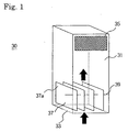
- a protective housing or cover 31 of a hydrogen recombining unit 30 for treating atmosphere containing hydrogen gas in a nuclear reactor containment vessel is provided with an intake port 33 at its lower portion and an exhaust port 35 at its upper side portion, respectively, and an air passage communicating thereto is defined therein.
- a catalyst bed 37 comprising a plurality of plate type catalyzers 37a is disposed in the air passage close to the intake port 33 and air flow paths are defined between the plate type catalyzers 37 thereby allowing the air to flow therethrough.
- an electric heater 39 is disposed extending through the plate type catalyzers 37 and its heating section is adjacent to the plate type catalyzers.
- the catalysts adjacent to the area where recombination reactions are generated are heated by heat conduction of the heat generation and the recombination reaction is promoted there to thus activate the entire area of the plate type catalyzers 37a.
- This activation promoting phenomenon on the plate type catalyzers 37a is generated over the entire catalyst bed 37 and the recombination of hydrogen and oxygen is promoted thereby resulting in rapid treatment of the hydrogen. Air that has risen in temperature through heat generated in the recombination reaction flows farther on through the gas passage and is discharged from the exhaust port 35.
- the electric heater 39 becomes a source of ignition and treats a large quantity of hydrogen gas by propagated combustion out of the device through the intake opening 33 or discharge opening 35.
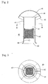
- a housing or container 41 of a hydrogen recombining unit 40 for treating an air containing hydrogen gas in a nuclear reactor containment vessel is provided with an intake port 43 at its lower portion and a discharge port 44 at its upper portion and an air passage 42 communicating therewith is defined therein.
- the discharge port 44 of the container 41 is covered with a protective cover 46 apart therefrom, and an annular exhaust opening 45 is defined at the side thereof.
- a catalyst bed 47 composed of honeycomb type catalysts is disposed in the air passage 42 inside of the container, and an electric heater 49 is disposed in the air passage 42 below the catalyst bed 47. A heating section of the electric heater 49 is close, but not adjacent to the catalyst bed 47.
- the hydrogen recombining unit 40 As described above, when hydrogen gas is generated resulting from an accident in the nuclear reactor containment vessel, a gas mixture containing hydrogen and oxygen, or hydrogen-gas-contained air flows into the air passage 42 in the container 41 through the intake port 43 and comes into contact with the catalyst bed 47. Thereafter, hydrogen and oxygen combine on surfaces of the catalysts thereby generating heat.
- the electric heater 49 is supplied with electricity and produces electric resistance heat thereby heating and activating a lower portion of the catalyst close thereto. As a result, the recombination reaction is promoted.
- the catalyst adjacent to an area where the combination reaction is caused is heated through conduction of heat by exothermic reaction and the recombination reaction there is promoted.
- the catalyst of the catalyst layer 47 is heated successively and the phenomenon of promoting the activation is created over the entire catalyst layer 47 thereby promoting combination of hydrogen and oxygen.
- the air that has risen in temperature from the heat of the recombination reaction flows through the air passage 42 and is discharged out through the exhaust opening 45.
- the electric heater 49 functions as an ignition source and treats a large quantities of hydrogen gas by the propagation of combustion wave.
- the heater serves as an ignition source and starts combustion reactions thereby rapidly treating the hydrogen.
Landscapes
- Chemical & Material Sciences (AREA)
- Organic Chemistry (AREA)
- Chemical Kinetics & Catalysis (AREA)
- High Energy & Nuclear Physics (AREA)
- Physics & Mathematics (AREA)
- General Engineering & Computer Science (AREA)
- Engineering & Computer Science (AREA)
- Inorganic Chemistry (AREA)
- Structure Of Emergency Protection For Nuclear Reactors (AREA)
- Gas Burners (AREA)
- Exhaust Gas Treatment By Means Of Catalyst (AREA)
- Catalysts (AREA)
- Devices And Processes Conducted In The Presence Of Fluids And Solid Particles (AREA)
Abstract
Description
- The present invention relates to an apparatus for treating air containing hydrogen gas, and in particular, an apparatus for safely treating the hydrogen gas contained in the air in a nuclear reactor containment vessel.
- When hydrogen gas is contained in air, hydrogen and oxygen coexist, making it easy for the hydrogen to begin a combustion reaction. Further since hydrogen reacts explosively with oxygen when the hydrogen concentration rises above a certain value, sufficient countermeasures must be provided in certain kinds of plants handling hydrogen gas or generating hydrogen gas. For example, in a nuclear power plant, if a nuclear core is heated excessively, zirconium in the zirconium base alloy used for fuel cladding tubes of the nuclear reactor fuel, etc., and water steam react with each other to produce a large quantity of hydrogen gas. Furthermore, radiolysis of water caused by radioactive material that flows into a sump in the nuclear reactor containment vessel during an accident generates a large quantity of hydrogen gas slowly but over a long period to accumulate it in the reactor containment vessel. When the hydrogen concentration in the atmosphere within the containment vessel rises above four percent, particularly above six percent, there is a possibility that the hydrogen will burn and the hydrogen will burn explosively if the concentration goes up above ten percent. Accordingly, to insure safety, the hydrogen gas must be treated and removed when it is in lower concentrations and concentration rises to higher levels must be prevented.
- In response to the needs described above, an electric hydrogen recombining unit, an ignition type hydrogen burner, a catalytic hydrogen recombining unit and the like have been proposed, are under development or are being used. Describing them in outline, the electric hydrogen recombining unit shown in Fig. 4 mainly used where the generation of hydrogen gas is slow and the concentration of hydrogen is less than four percent, treats hydrogen by taking a gas mixture of hydrogen and air though a
suction port 3 into the recombining unit and discharges an exhaust gas from an exhaust port 7 after hydrogen and oxygen is recombined with anelectric heater 5. - The ignition
type hydrogen burner 10 shown in Figs. 5 and 6 is installed in a free space and aheater 13 is energized from anelectric source 11 of about 120V to ignite a gas mixture containing hydrogen and to burn the hydrogen content by propagating a flame. In addition, the ignitiontype hydrogen burner 10 has aprotective housing 15, a conduit for electric supply, and aprotective umbrella 19 in addition to theheater 13. Thisprotective umbrella 19 protects theheater 13 from liquid droplets sprayed from emergency cooling sprays in the containment vessel. - Furthermore, the catalytic hydrogen recombining unit 20 shown in Fig. 7 is composed of a
removable catalyzer bed 21 consisting of a stack of plate type catalyst carrying platinum or palladium as the catalytic substance deposited thereon, an intake opening 23, an exhaust opening 25 and aprotective housing 27. Then, when hydrogen gas is generated in a containment vessel where it is installed, a gas mixture containing hydrogen and oxygen flows into thecatalyzer bed 21 through the intake opening 23 under natural circulation. Hydrogen and oxygen recombine on the catalytic surface in thecatalyzer bed 21, thecatalyzer bed 21 is heated with the heat of reaction, and the gas takes on a hot state as it passes through thecatalyzer bed 21. The catalyst is activated by being heated and the reaction is further activated. Thereafter, the heated hot discharge gas is exhausted through the exhaust opening 25 to complete the treatment of the hydrogen gas. - In the electric hydrogen recombining unit described before, there are problems in that the treatment is slow because it is performed under recombining reaction without burning propagation and in that the apparatus can not be actually used for gas mixtures with a hydrogen concentration above four percent in order to protect the apparatus from the strong combustion that would occur.
- Further, although the ignition type hydrogen burner can treat a large quantity of hydrogen within a free space in a short period of time because the gas mixture containing hydrogen is directly ignited and a pilot (flame) is propagated therein, there is another problem in that hydrogen can not be treated when the hydrogen concentration is below about six percent above which the flame can propagate with burning. In spite of the advantages of the burner, it can be said that the use thereof should be confined to emergency situations when a large quantity of hydrogen gas is produced, because the treatment uses flames and there is a fear that other equipment such as safety system components, electricity supply cables and nuclear instrumentation systems may be adversely influenced.
- Furthermore, though the catalytic hydrogen recombining unit can treat gas mixtures to remove hydrogen in a wide range of lower to higher concentrations, the treatment speed is so slow that generated hydrogen gas can not be wholly treated when a large quantity of the gas is generated in a short period, thereby allowing the generation of higher hydrogen concentrations. An ignition in those states of higher hydrogen concentration raises another problem by causing deflagration or detonation. Besides, in an emergency situation such as a case when a large amount of hydrogen gas is generated, there is a problem that various kinds of substances are included into an atmosphere in the containment vessel and the catalyst can be poisoned by poisoning substances in the included ones so as to lower the activity of the catalyst, making the treatment of the hydrogen gas impossible.
- Accordingly, an object of the present invention is to provide a treatment apparatus for an air containing hydrogen gas which can reliably and safely treat hydrogen in a gaseous mixture containing hydrogen even with any concentration of hydrogen or with various kinds of poisoning substances contained in the gaseous mixture.
- In order to solve the problems described above, according to the present invention, an apparatus for air containing hydrogen gas comprises a housing defining a gas passage therein with an intake port and an exhaust port, a catalyst bed disposed in the gas passage and a heater disposed in or adjacent to the catalyst bed. In an embodiment where the catalyst bed is composed of a plate type catalyzer, an electric heater maybe disposed by extending it through and laying it in contact with the catalyst bed, and in another embodiment where the catalyst is composed of a honey comb type catalyzer, it is preferred that an electric heater be disposed in the gas passage at an upstream side of and close to the honey comb type catalyzer.
-
- Fig. 1 is a schematic view showing a general construction of the embodiment according to the present invention;
- Fig. 2 is a sectional elevational view showing another embodiment according to the present invention;
- Fig. 3 is a horizontal sectional view taken off along line III - III in Fig. 1;
- Fig. 4 is a general perspective view showing an example of prior art apparatus;
- Fig. 5 is a general perspective view of another prior art apparatus;
- Fig. 6 is an enlarged view showing a portion in Fig. 5; and
- Fig. 7 is an exploded view of another prior art apparatus.
-
- In reference to the drawings attached, an embodiment of the present invention is hereinbelow described. Referring to Fig. 1 first, a protective housing or
cover 31 of ahydrogen recombining unit 30 for treating atmosphere containing hydrogen gas in a nuclear reactor containment vessel is provided with anintake port 33 at its lower portion and anexhaust port 35 at its upper side portion, respectively, and an air passage communicating thereto is defined therein. Further, acatalyst bed 37 comprising a plurality ofplate type catalyzers 37a is disposed in the air passage close to theintake port 33 and air flow paths are defined between theplate type catalyzers 37 thereby allowing the air to flow therethrough. Further, anelectric heater 39 is disposed extending through theplate type catalyzers 37 and its heating section is adjacent to the plate type catalyzers. - In the
hydrogen recombining unit 30 with the construction described above, when hydrogen gas is generated resulting from an accident in the nuclear reactor containment vessel, a gaseous mixture containing hydrogen and oxygen, that is, air containing hydrogen gas flows through theintake port 33 into the gas passage in thecover 31 and on the catalytic surfaces of theplate type catalyzers 37a hydrogen and oxygen combine with the generation of heat. During an accident where there is the generation of hydrogen gas, theelectric heater 39 is designed to be energized to generate electric resistance heat thereby heating adjacent catalysts, activating them and to promote recombination reaction. The catalysts adjacent to the area where recombination reactions are generated are heated by heat conduction of the heat generation and the recombination reaction is promoted there to thus activate the entire area of theplate type catalyzers 37a. This activation promoting phenomenon on theplate type catalyzers 37a is generated over theentire catalyst bed 37 and the recombination of hydrogen and oxygen is promoted thereby resulting in rapid treatment of the hydrogen. Air that has risen in temperature through heat generated in the recombination reaction flows farther on through the gas passage and is discharged from theexhaust port 35. - During abnormal conditions when hydrogen gas is generated, although the mixture containing water steam and poison material produced with the leaking out of the coolant at high pressure and high temperature flows in though the intake opening 33 and comes into contact with the
catalyzer bed 37, the hydrogen gas treatment is rapidly performed with the aid of catalyst activation caused by the heating of theelectric heater 39. - In addition, when the hydrogen concentration rises above four percent from the generation of large quantities of hydrogen gas, the
electric heater 39 becomes a source of ignition and treats a large quantity of hydrogen gas by propagated combustion out of the device through theintake opening 33 ordischarge opening 35. - Next, a hydrogen recombining unit using a honey comb type catalyst will be described. Referring to Figs. 2 and 3, a housing or
container 41 of ahydrogen recombining unit 40 for treating an air containing hydrogen gas in a nuclear reactor containment vessel is provided with anintake port 43 at its lower portion and adischarge port 44 at its upper portion and anair passage 42 communicating therewith is defined therein. Thedischarge port 44 of thecontainer 41 is covered with aprotective cover 46 apart therefrom, and anannular exhaust opening 45 is defined at the side thereof. Then, acatalyst bed 47 composed of honeycomb type catalysts is disposed in theair passage 42 inside of the container, and anelectric heater 49 is disposed in theair passage 42 below thecatalyst bed 47. A heating section of theelectric heater 49 is close, but not adjacent to thecatalyst bed 47. - In the
hydrogen recombining unit 40 as described above, when hydrogen gas is generated resulting from an accident in the nuclear reactor containment vessel, a gas mixture containing hydrogen and oxygen, or hydrogen-gas-contained air flows into theair passage 42 in thecontainer 41 through theintake port 43 and comes into contact with thecatalyst bed 47. Thereafter, hydrogen and oxygen combine on surfaces of the catalysts thereby generating heat. During the accident when the hydrogen gas is generated, theelectric heater 49 is supplied with electricity and produces electric resistance heat thereby heating and activating a lower portion of the catalyst close thereto. As a result, the recombination reaction is promoted. The catalyst adjacent to an area where the combination reaction is caused is heated through conduction of heat by exothermic reaction and the recombination reaction there is promoted. Thus, the catalyst of thecatalyst layer 47 is heated successively and the phenomenon of promoting the activation is created over theentire catalyst layer 47 thereby promoting combination of hydrogen and oxygen. The air that has risen in temperature from the heat of the recombination reaction flows through theair passage 42 and is discharged out through theexhaust opening 45. - During abnormal conditions when hydrogen gas is generated, although the mixture containing water steam and poison material produced with the leaking out of the coolant at high pressure and high temperature flows in though the
intake port 43 and comes into contact with thecatalyzer layer 47, the hydrogen gas treatment is rapidly performed with the aid of catalyst activation caused by the heating of theelectric heater 49. - In addition, when the hydrogen concentration rises above four percent from the generation of a large quantities of hydrogen gas, the
electric heater 49 functions as an ignition source and treats a large quantities of hydrogen gas by the propagation of combustion wave. - As described above, according to the invention, when hydrogen concentration in the air is low the hydrogen gas is treated by quick accomplishment of hydrogen recombination reaction with assistance of the catalyst activation which is promoted with the heater, while when the hydrogen concentration largely rises upon generation of a large quantity of the hydrogen gas, the heater serves as an ignition source and starts combustion reactions thereby rapidly treating the hydrogen.
Claims (3)
- An apparatus for treating air containing hydrogen gas, characterized in that the apparatus comprises a housing provided with an intake port and an exhaust port and defining a gas passage therein, a catalyst bed disposed in said gas passage, and a heater disposed in or close to said catalyst bed.
- The apparatus for treating air containing hydrogen gas as described in claim 1, characterized in that said catalyst bed is composed of plate type catalysts and an electric heater as said heater is disposed extending through the plate type catalysts.
- The apparatus for treating air containing hydrogen gas as described in claim 1, characterized in that said catalyst bed is composed of honeycomb type catalysts and an electric heater as said heater is disposed close to the honeycomb catalysts on an upstream side of the honeycomb catalysts in said gas passage.
Applications Claiming Priority (3)
| Application Number | Priority Date | Filing Date | Title |
|---|---|---|---|
| JP2396997 | 1997-02-06 | ||
| JP9023969A JPH10221490A (en) | 1997-02-06 | 1997-02-06 | Device for treating air containing hydrogen gas |
| PCT/JP1998/000485 WO1998035357A1 (en) | 1997-02-06 | 1998-02-05 | Apparatus for treating air containing hydrogen gas |
Publications (2)
| Publication Number | Publication Date |
|---|---|
| EP0929078A1 true EP0929078A1 (en) | 1999-07-14 |
| EP0929078A4 EP0929078A4 (en) | 2002-05-15 |
Family
ID=12125391
Family Applications (1)
| Application Number | Title | Priority Date | Filing Date |
|---|---|---|---|
| EP98901523A Withdrawn EP0929078A4 (en) | 1997-02-06 | 1998-02-05 | Apparatus for treating air containing hydrogen gas |
Country Status (7)
| Country | Link |
|---|---|
| EP (1) | EP0929078A4 (en) |
| JP (1) | JPH10221490A (en) |
| KR (1) | KR100309061B1 (en) |
| CN (1) | CN1216142A (en) |
| CA (1) | CA2249581C (en) |
| ID (1) | ID21815A (en) |
| WO (1) | WO1998035357A1 (en) |
Cited By (2)
| Publication number | Priority date | Publication date | Assignee | Title |
|---|---|---|---|---|
| DE102007060372A1 (en) * | 2007-12-12 | 2009-06-18 | Areva Np Gmbh | Rekombinatorelement |
| EP3622536A4 (en) * | 2017-05-10 | 2020-12-30 | Westinghouse Electric Company Llc | A vortex driven passive hydrogen recombiner and igniter |
Families Citing this family (5)
| Publication number | Priority date | Publication date | Assignee | Title |
|---|---|---|---|---|
| KR101636394B1 (en) * | 2014-12-22 | 2016-07-06 | 한국원자력연구원 | Containment filtered venting system having hydrogen reduction unit |
| CN107335426A (en) * | 2017-06-30 | 2017-11-10 | 东南大学 | Flat catalyst can adjust based on the electrically heated temperature of matrix |
| CN108053896B (en) * | 2017-11-28 | 2020-02-21 | 上海交通大学 | Hydrogen catalysis recombiner |
| JP7147508B2 (en) * | 2018-11-22 | 2022-10-05 | 株式会社Ihi | RADIOACTIVE WASTE TRANSPORTATION EQUIPMENT AND METHOD FOR CHARGING RADIOACTIVE WASTE FOR RADIOACTIVE WASTE TRANSPORTATION EQUIPMENT |
| CN113380430A (en) * | 2021-06-03 | 2021-09-10 | 哈尔滨工程大学 | Hydrogen recombiner catalyst loading box |
Citations (4)
| Publication number | Priority date | Publication date | Assignee | Title |
|---|---|---|---|---|
| US4741879A (en) * | 1986-06-10 | 1988-05-03 | The United States Of America As Represented By The United States Department Of Energy | Catalytic igniters and their use to ignite lean hydrogen-air mixtures |
| US5262131A (en) * | 1992-05-08 | 1993-11-16 | Abb Air Preheater, Inc. | Catalytic regenerative thermal oxidizer |
| US5492686A (en) * | 1991-07-29 | 1996-02-20 | Siemens Aktiengesellschaft | Process and device for recombining and/or igniting hydrogen contained in an H2 -air-steam mixture, preferably for nuclear power stations |
| WO1998011561A1 (en) * | 1996-09-09 | 1998-03-19 | Siemens Aktiengesellschaft | Process and device for initiating a hydrogen-oxygen reaction in a reactor safety container |
Family Cites Families (5)
| Publication number | Priority date | Publication date | Assignee | Title |
|---|---|---|---|---|
| JPS5655215Y2 (en) * | 1977-06-29 | 1981-12-23 | ||
| JPS55158600A (en) * | 1979-05-28 | 1980-12-10 | Tokyo Shibaura Electric Co | Recombiner |
| JPS5920719Y2 (en) * | 1980-07-09 | 1984-06-15 | 株式会社日立製作所 | oxyhydrogen recombiner |
| JPS59119297A (en) * | 1982-12-25 | 1984-07-10 | 株式会社東芝 | Radioactive gaseous waste processing device |
| JPH077096B2 (en) * | 1988-04-22 | 1995-01-30 | 日本碍子株式会社 | Exhaust gas recombiner |
-
1997
- 1997-02-06 JP JP9023969A patent/JPH10221490A/en not_active Withdrawn
-
1998
- 1998-02-05 EP EP98901523A patent/EP0929078A4/en not_active Withdrawn
- 1998-02-05 WO PCT/JP1998/000485 patent/WO1998035357A1/en not_active Application Discontinuation
- 1998-02-05 CN CN199898800104A patent/CN1216142A/en active Pending
- 1998-02-05 CA CA002249581A patent/CA2249581C/en not_active Expired - Fee Related
- 1998-02-05 KR KR1019980707804A patent/KR100309061B1/en not_active IP Right Cessation
- 1998-02-05 ID IDW980096D patent/ID21815A/en unknown
Patent Citations (4)
| Publication number | Priority date | Publication date | Assignee | Title |
|---|---|---|---|---|
| US4741879A (en) * | 1986-06-10 | 1988-05-03 | The United States Of America As Represented By The United States Department Of Energy | Catalytic igniters and their use to ignite lean hydrogen-air mixtures |
| US5492686A (en) * | 1991-07-29 | 1996-02-20 | Siemens Aktiengesellschaft | Process and device for recombining and/or igniting hydrogen contained in an H2 -air-steam mixture, preferably for nuclear power stations |
| US5262131A (en) * | 1992-05-08 | 1993-11-16 | Abb Air Preheater, Inc. | Catalytic regenerative thermal oxidizer |
| WO1998011561A1 (en) * | 1996-09-09 | 1998-03-19 | Siemens Aktiengesellschaft | Process and device for initiating a hydrogen-oxygen reaction in a reactor safety container |
Non-Patent Citations (1)
| Title |
|---|
| See also references of WO9835357A1 * |
Cited By (4)
| Publication number | Priority date | Publication date | Assignee | Title |
|---|---|---|---|---|
| DE102007060372A1 (en) * | 2007-12-12 | 2009-06-18 | Areva Np Gmbh | Rekombinatorelement |
| DE102007060372B4 (en) * | 2007-12-12 | 2010-11-18 | Areva Np Gmbh | Rekombinatorelement |
| EP3622536A4 (en) * | 2017-05-10 | 2020-12-30 | Westinghouse Electric Company Llc | A vortex driven passive hydrogen recombiner and igniter |
| US11923099B2 (en) | 2017-05-10 | 2024-03-05 | Westinghouse Electric Company Llc | Vortex driven passive hydrogen recombiner and igniter |
Also Published As
| Publication number | Publication date |
|---|---|
| EP0929078A4 (en) | 2002-05-15 |
| CA2249581C (en) | 2003-04-01 |
| CA2249581A1 (en) | 1998-08-13 |
| CN1216142A (en) | 1999-05-05 |
| KR100309061B1 (en) | 2001-12-12 |
| WO1998035357A1 (en) | 1998-08-13 |
| KR20000064828A (en) | 2000-11-06 |
| ID21815A (en) | 1999-07-29 |
| JPH10221490A (en) | 1998-08-21 |
Similar Documents
| Publication | Publication Date | Title |
|---|---|---|
| KR100495803B1 (en) | Recombination device and method for catalytically recombining hydrogen and/or carbon monoxide with oxygen in a gaseous mixture | |
| JP3486663B2 (en) | Catalyst system and recombination device for recombination of hydrogen and oxygen, especially for nuclear power plants | |
| US4228132A (en) | Hydrogen-oxygen recombiner | |
| JP4074200B2 (en) | Gas catalytic oxidation method and recombination apparatus and system | |
| JP4677418B2 (en) | Diesel engine exhaust system | |
| CN101896979B (en) | Recombiner element | |
| CA2249581C (en) | Apparatus for treating air containing hydrogen gas | |
| RU2188471C2 (en) | Gas-mixture hydrogen recombination device | |
| CN104575632A (en) | Combustion controller for combustible gas | |
| WO1998022209A1 (en) | SELECTIVE CATALYTIC NOx REDUCTION UTILIZING UREA WITHOUT CATALYST FOULING | |
| US4139603A (en) | Hydrogen-oxygen recombiner | |
| RU2134917C1 (en) | Device for passive inactivation of gas mixture in containment of nuclear power plant | |
| US20010055360A1 (en) | Apparatus for treating air containing hydrogen gas | |
| EP0748984B1 (en) | Method and device for destroying reaction gases by incineration | |
| JP6865773B2 (en) | How to ensure the safety of hydrogen explosions at nuclear power plants | |
| JP3566303B2 (en) | Method and apparatus for initiating the reaction between hydrogen and oxygen in containment of a nuclear reactor | |
| US6846775B1 (en) | Recombinator for eliminating hydrogen from accident atmospheres | |
| JPS62254366A (en) | Off-gas purification and combustion device for fuel cell generation system | |
| RU2599145C1 (en) | Recombiner and method for recombination of hydrogen or methane and oxygen in gas mixture | |
| JP5632272B2 (en) | Hydrogen treatment facility for reactor containment vessel | |
| KR101443042B1 (en) | Passive hydrogen remove imitate device for loss of heat of filtration test chamber | |
| Gera et al. | Hydrogen Recombiner CFD Model: Development, Benchmarking and Performance Evaluation | |
| US5846504A (en) | Emission control device for preventing organic compounds emissions | |
| Hosler et al. | PARs for combustible gas control in advanced light water reactors | |
| Weems et al. | Hydrogen--oxygen recombiner |
Legal Events
| Date | Code | Title | Description |
|---|---|---|---|
| PUAI | Public reference made under article 153(3) epc to a published international application that has entered the european phase |
Free format text: ORIGINAL CODE: 0009012 |
|
| AK | Designated contracting states |
Kind code of ref document: A1 Designated state(s): DE FR |
|
| A4 | Supplementary search report drawn up and despatched |
Effective date: 20020328 |
|
| AK | Designated contracting states |
Kind code of ref document: A4 Designated state(s): DE FR |
|
| RIC1 | Information provided on ipc code assigned before grant |
Free format text: 7G 21F 9/02 A, 7G 21D 3/08 B, 7G 21C 19/317 B, 7G 21C 9/004 B |
|
| 17P | Request for examination filed |
Effective date: 19980921 |
|
| 17Q | First examination report despatched |
Effective date: 20041012 |
|
| STAA | Information on the status of an ep patent application or granted ep patent |
Free format text: STATUS: THE APPLICATION IS DEEMED TO BE WITHDRAWN |
|
| 18D | Application deemed to be withdrawn |
Effective date: 20050223 |